LAND ROVER FRELANDER 2 2006 Repair Manual
Manufacturer: LAND ROVER, Model Year: 2006, Model line: FRELANDER 2, Model: LAND ROVER FRELANDER 2 2006Pages: 3229, PDF Size: 78.5 MB
Page 2551 of 3229
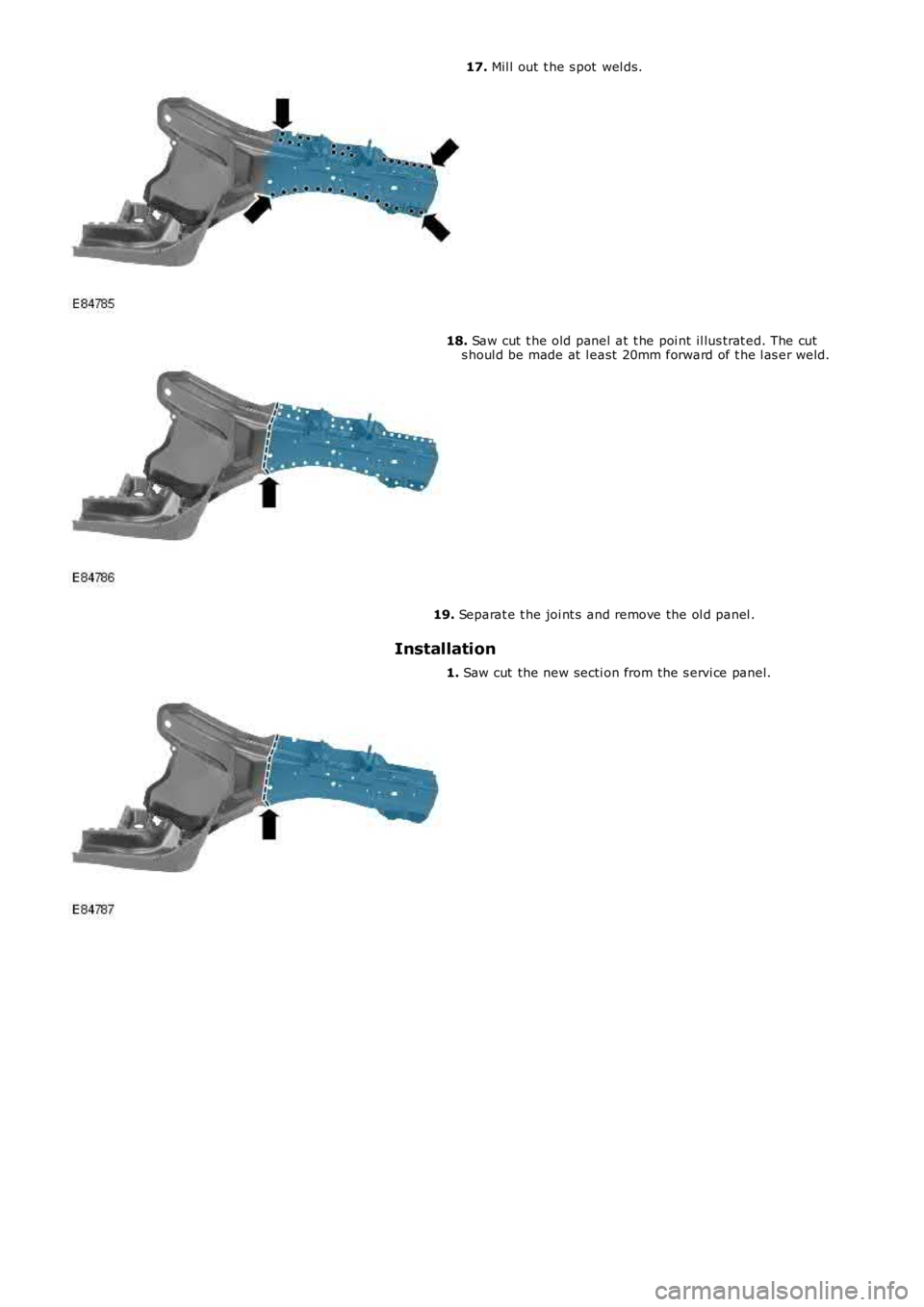
17. Mil l out t he s pot wel ds.
18. Saw cut t he old panel at t he poi nt il lus trat ed. The cuts houl d be made at l east 20mm forward of t he l as er weld.
19. Separat e t he joi nt s and remove the ol d panel .
Installation
1. Saw cut the new secti on from the s ervi ce panel.
Page 2552 of 3229
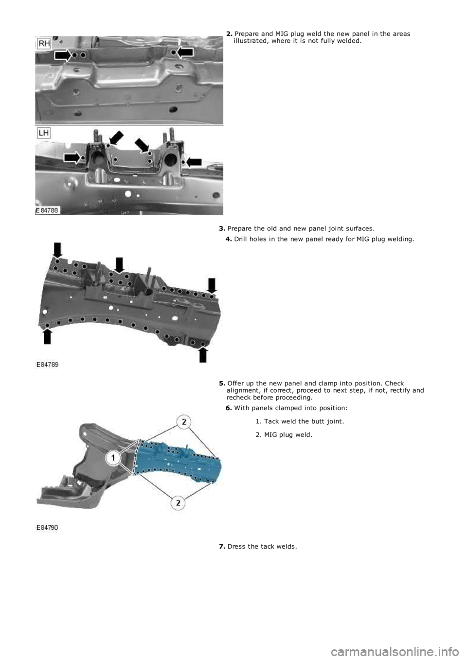
2. Prepare and MIG pl ug weld the new panel in the areasi llus t rat ed, where it i s not full y welded.
3. Prepare t he old and new panel joi nt s urfaces.
4. Dri ll holes i n the new panel ready for MIG plug wel di ng.
5. Offer up the new panel and clamp i nto pos it ion. Checkali gnment , if correct , proceed to next s tep, i f not , recti fy andrecheck before proceeding.
6. W i th panels cl amped into pos i ti on:
1. Tack weld t he butt joint .
2. MIG pl ug weld.
7. Dres s t he tack welds .
Page 2553 of 3229
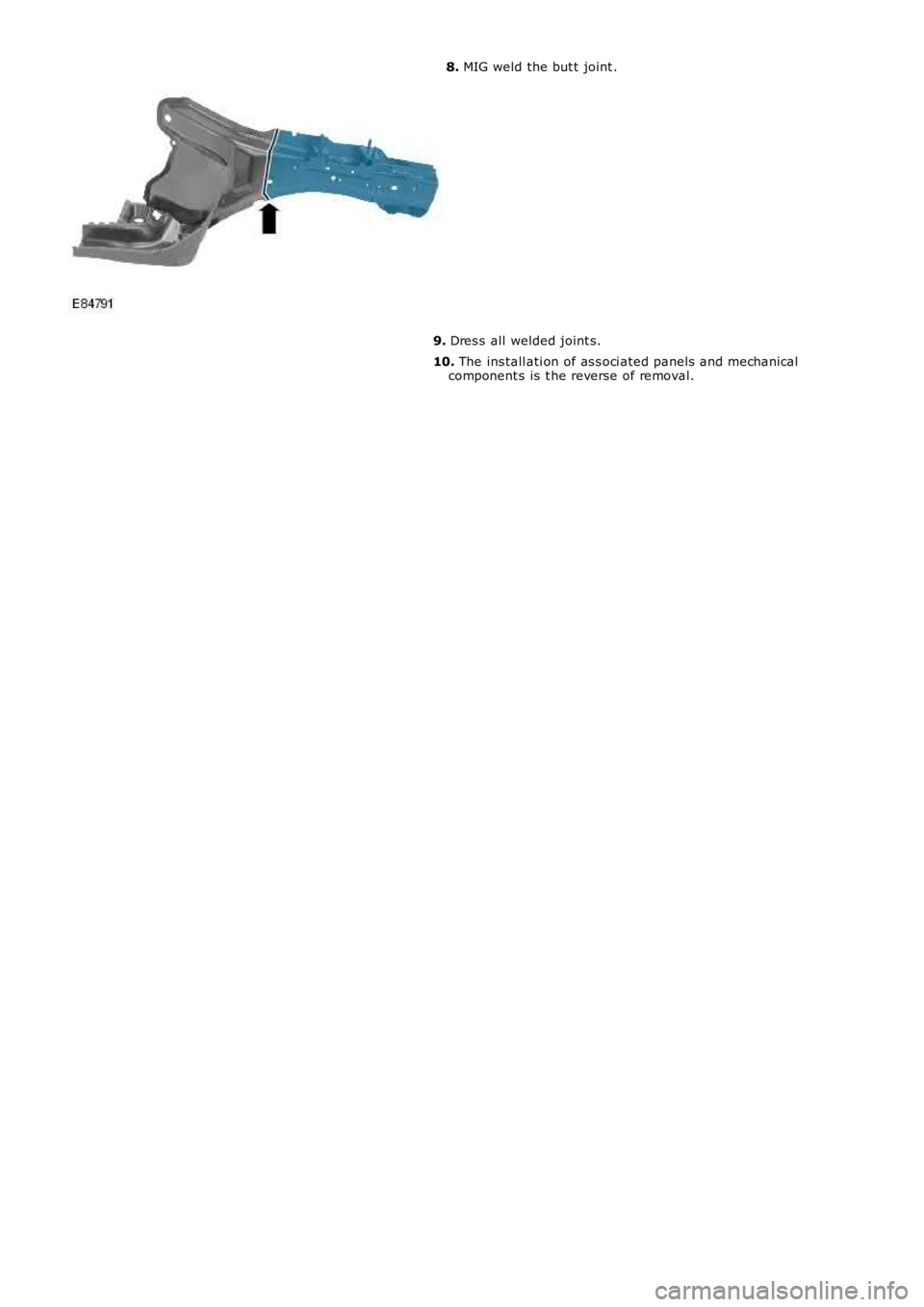
8. MIG weld the but t joint .
9. Dres s all welded joint s.
10. The ins tall ati on of as s oci ated panels and mechanicalcomponent s is t he reverse of removal.
Page 2554 of 3229
Publi s hed: 11-May-2011
Front End Sheet Metal Repairs - Suspension Top Mount
Removal and Inst all ati on
Removal
• NOTE: The s uspens ion t op mount is s ervi ced as a s eparate wel d-on panel.
• NOTE: The s ervice panel is not ful ly wel ded.
• NOTE: The panel i s s erviced les s i ts wel d s t uds
1. The sus pens i on top mount i s repl aced i n conjunct ion wi th:
Front bumper cover
Front bumper armature
Hood
Hood lat ch panel
Both front fenders
Fender apron upper panel
Fender apron panel
Ins t rument panel
• NOTE: It is al so neces sary t o remove t he engine and s us pens ion as an as s embly.
2. For addit ional informati on rel at ing to this repair procedurepleas e s ee t he foll owing:For addi ti onal informat ion, refer t o: Body and Frame (501-26Body Repai rs - Vehi cl e Speci fic Informat ion and ToleranceChecks , Descripti on and Operat ion) /Standard W orks hop Practi ces (100-00 General Informat ion,Des cript ion and Operat ion).
3. Remove the fender apron panel.For addi ti onal informat ion, refer t o: Fender Apron Panel(501-27 Front End Sheet Met al Repairs , Removal andIns t allat ion).
4. Remove the i nst rument panel.For addi ti onal informat ion, refer t o: Ins t rument Panel - TD42.2L Di esel (501-12 Ins t rument Panel and Cons ole, Removaland Ins t allat ion).
5. Remove the rocker panel i nner t ri m panel.
6. Remove the B-pill ar lower trim panel .For addi ti onal informat ion, refer t o: B-Pi ll ar Lower Tri m Panel(501-05 Int eri or Trim and Ornament ati on, Removal andIns t allat ion).
7. Remove the engine and front s uspens ion as an as s embly.
8. RH Side: Remove t he pedal box.
9. RH Side: Remove t he brake mas ter cylinder.For addi ti onal informat ion, refer t o: Brake Mas t er Cyli nder(206-06 Hydraulic Brake Actuati on, Removal and Ins t al lat ion).
10. Rel eas e and l ay as ide t he carpet and ins ul ati ng mat erial att he inner bul khead.
11. Rel eas e and l ay as ide t he wiring harnes s .
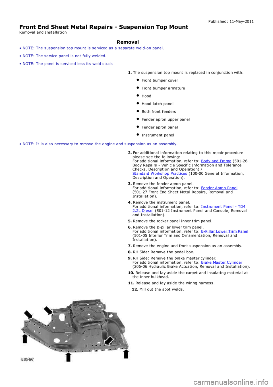
12. Mil l out t he s pot wel ds.
Page 2555 of 3229
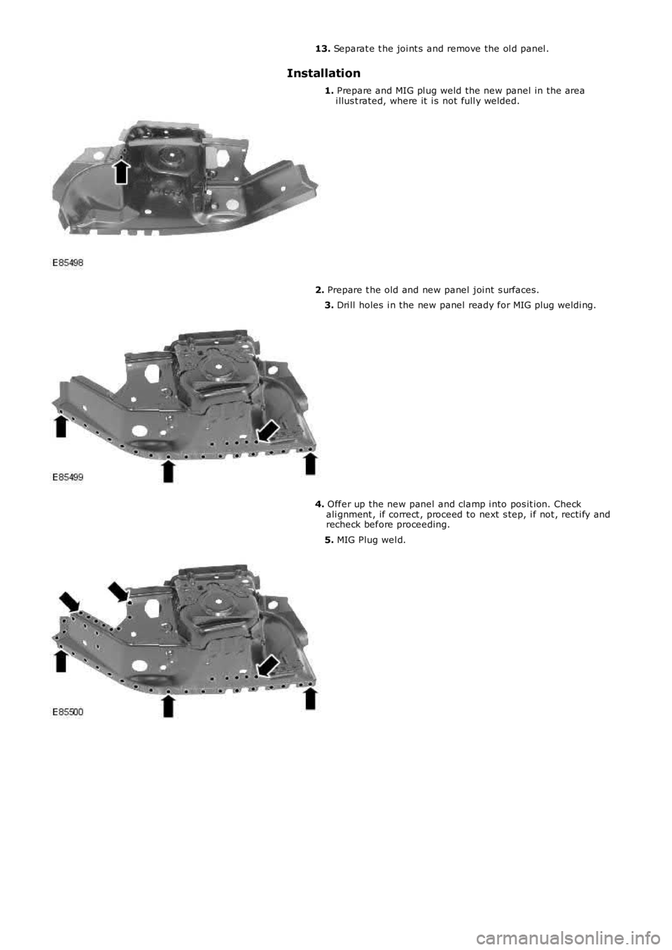
13. Separat e t he joi nt s and remove the ol d panel .
Installation
1. Prepare and MIG pl ug weld the new panel in the areai llus t rated, where it i s not full y welded.
2. Prepare t he old and new panel joi nt s urfaces.
3. Dri ll holes i n the new panel ready for MIG plug wel di ng.
4. Offer up the new panel and clamp i nto pos it ion. Checkali gnment , if correct , proceed to next s tep, i f not , recti fy andrecheck before proceeding.
5. MIG Plug wel d.
Page 2556 of 3229
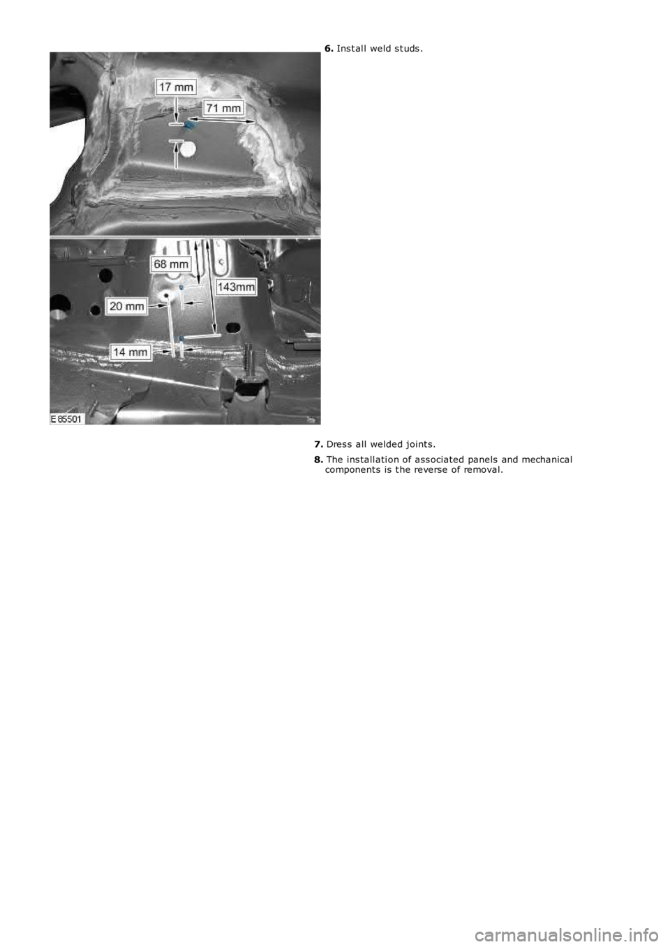
6. Ins t al l weld s t uds .
7. Dres s all welded joint s.
8. The ins tall ati on of ass ociated panels and mechanicalcomponent s is t he reverse of removal.
Page 2557 of 3229
Publ is hed: 11-May-2011
Front End Sheet Metal Repairs - Front Side Member Section
Removal and Installation
Removal
• NOTE: The front side member section is cut from the front side member service panel.
• NOTE: The RH section is slightly shorter than the LH due to the location of the engine mounting.
• NOTE: Due to the combined thickness of the panels, it is recommended that spot welds are replaced with MIG plug welds
in this repair.
1. The front s ide member s ect ion is replaced in conjunct ion wit h:
Front bumper cover
Front bumpe r a rma t ure
Hood lat ch panel
Both front fenders
Front bumpe r mount i ng
• NOTE: It is also necessary to remove the engine and suspension as an assembly.
2. Fo r a d d i t i o na l i nf o rma t i o n re l a t i ng t o t hi s re p a i r p ro ce d ure
please see the following:
Fo r a d d i t i o na l i nf o rma t i o n, re f e r t o : Body and Frame
(501-26
Body Repairs - Vehicle Specific Information and Tolerance
Checks, Description and Operation) /
St a nd a rd W o rks ho p P ra ct i ce s
(100-00 Ge ne ra l I nf o rma t i o n,
Description and Operation).
3. Re move t he f ront bumpe r mount i ng.
Fo r a d d i t i o na l i nf o rma t i o n, re f e r t o : Front Bumper Mount ing
(501-27 Front End Sheet Met al Re pai rs , Removal and
Installation).
4. Remove the radiator cooling pack.
Fo r a d d i t i o na l i nf o rma t i o n, re f e r t o : Radiator
(303-03A Engi ne
Cooling - I6 3.2L Petrol, Removal and Installation).
5. Remove the engine and front suspension as an assembly.
6. LH Side: Remove the air intake pipe.
7. LH Side: Release the battery junction box and position aside.
8. RH Side: Remove the windshield washer reservoir.
Fo r a d d i t i o na l i nf o rma t i o n, re f e r t o : Windshield Washer
Res ervoi r (501-16 W i pers and W as hers , Removal and
Installation).
9. Release and lay aside the wiring harness.
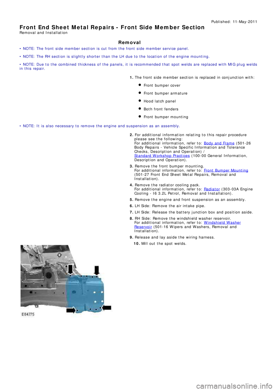
10. Mill out the spot welds.
Page 2558 of 3229
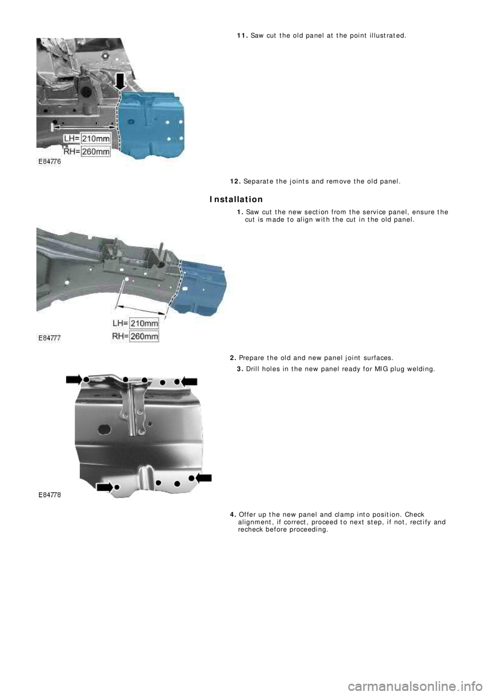
11. Saw cut the old panel at the point illustrated.
12. Separate the joints and remove the old panel.
Installation
1. Saw cut the new section from the service panel, ensure the
cut is made to align with the cut in the old panel.
2. Prepare the old and new panel joint surfaces.
3. Drill holes in the new panel ready for MIG plug welding.
4. Offer up the new panel and clamp into position. Check
al ignment , i f correct , proceed t o next s t ep, i f not , rect i fy and
recheck before proceeding.
Page 2559 of 3229
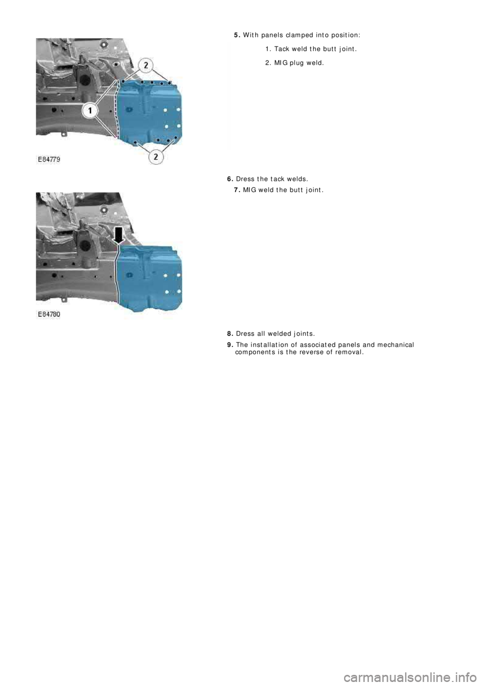
5. W ith panels clamped into position:
1. Tack weld the butt joint.
2. MIG pl ug wel d.
6. Dress the tack welds.
7. MIG weld the butt joint.
8. Dress all welded joints.
9. The installation of associated panels and mechanical
components is the reverse of removal.
Page 2560 of 3229
Publ is hed: 11-May-2011
Front End Sheet Metal Repairs - Fender Apron Panel
Removal and Installation
Removal
• NOTE: The fender apron panel is serviced as a separate weld-on panel. It is an assembly of the fender apron panel
reinforcement, fender apron lower panel and fender apron panel front extension.
• NOTE: The panel is serviced less its weld studs
1. The fender apron panel is replaced in conjunction with:
Front bumper cover
Hood lat ch panel
Both front fenders
Fender apron upper panel
2. Fo r a d d i t i o na l i nf o rma t i o n re l a t i ng t o t hi s re p a i r p ro ce d ure
please see the following:
Fo r a d d i t i o na l i nf o rma t i o n, re f e r t o : Body and Frame
(501-26
Body Repairs - Vehicle Specific Information and Tolerance
Checks, Description and Operation) /
St a nd a rd W o rks ho p P ra ct i ce s
(100-00 Ge ne ra l I nf o rma t i o n,
Description and Operation).
3. Remove the fender apron upper panel.
Fo r a d d i t i o na l i nf o rma t i o n, re f e r t o : Fender Apron Upper Panel
(501-27 Front End Sheet Met al Re pai rs , Removal and
Installation).
4. L H Si d e : Re mo ve t he a i r cl e a ne r.
Fo r a d d i t i o na l i nf o rma t i o n, re f e r t o : Air Cleaner
(303-12A
I nt a ke A i r Di s t ri b ut i o n a nd Fi l t e ri ng - I 6 3. 2L P e t ro l , Re mo va l
and Installation).
5. LH Side: Remove the air intake pipe.
6. LH Side: Remove the bat tery t ray.
Fo r a d d i t i o na l i nf o rma t i o n, re f e r t o : Battery Tray
(414-01
Battery, Mounting and Cables, Removal and Installation).
7. LH Side: Remove the engine lower support insulator.
Fo r a d d i t i o na l i nf o rma t i o n, re f e r t o : Engine Lower Support
Insulator (303-01A Engi ne - I6 3.2L Pet rol, Removal and
Installation).
8. LH Side: Release the battery junction box and position aside.
9. RH Side: Drain the cooling system.
Fo r a d d i t i o na l i nf o rma t i o n, re f e r t o : Cooling Sys tem Draining,
Filling and Bleeding (303-03A Engine Cooling - I6 3.2L Petrol,
General Procedures ).
10. RH Side: Evacuate the A/C system.
Fo r a d d i t i o na l i nf o rma t i o n, re f e r t o : Air Conditioning (A/C)
System Recovery, Evacuation and Charging (412-00 Cl i mat e
Co nt ro l Sys t e m - Ge ne ra l I nf o rma t i o n, Ge ne ra l P ro ce d ure s ).
11. RH Si d e : Re mo ve t he p o we r s t e e ri ng re s e rvo i r.
Fo r a d d i t i o na l i nf o rma t i o n, re f e r t o : P o we r St e e ri ng Fl ui d
Res ervoi r (211-02 Power St eeri ng, Removal and Ins t al lat i on).
12. RH Side: Release the coolant expansion tank and position
aside.
13. RH Side: Remove the engine mounting bracket.
Fo r a d d i t i o na l i nf o rma t i o n, re f e r t o : Engine Mount RH
(303-01A
Engine - I6 3.2L Petrol, Removal and Installation).
14. RH Side: Remove the windshield washer reservoir.
Fo r a d d i t i o na l i nf o rma t i o n, re f e r t o : Windshield Washer
Res ervoi r (501-16 W i pers and W as hers , Removal and
Installation).
15. RH Side: Remove the fender apron A/C pipes.
16. Remove the shock absorber and spring assembly.
Fo r a d d i t i o na l i nf o rma t i o n, re f e r t o : Sho ck A b s o rb e r a nd Sp ri ng
Assembly (204-01 Front Sus pens i on, Removal and
Installation).
17. Release and lay aside the wiring harness.