LAND ROVER FRELANDER 2 2006 Repair Manual
Manufacturer: LAND ROVER, Model Year: 2006, Model line: FRELANDER 2, Model: LAND ROVER FRELANDER 2 2006Pages: 3229, PDF Size: 78.5 MB
Page 2511 of 3229
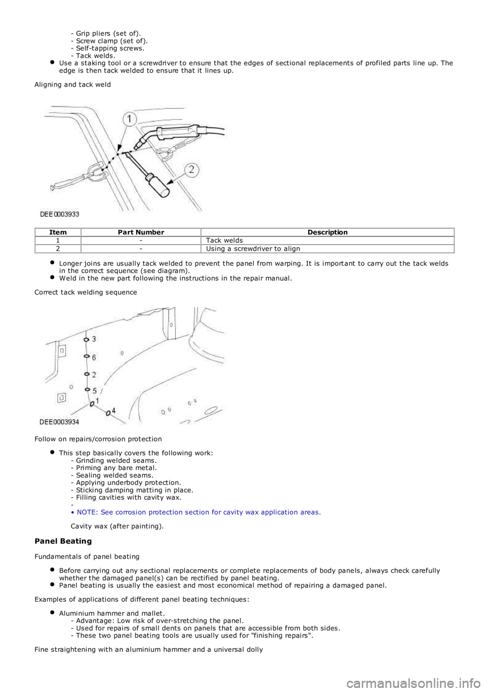
- Grip pl iers (s et of).- Screw cl amp (set of).- Self-t appi ng s crews.- Tack welds .Us e a s t aki ng tool or a s crewdri ver t o ens ure t hat the edges of s ect ional replacement s of profil ed parts li ne up. Theedge is t hen t ack wel ded to ens ure that it lines up.
Ali gni ng and t ack wel d
ItemPart NumberDescription1-Tack wel ds
2-Us ing a screwdriver to align
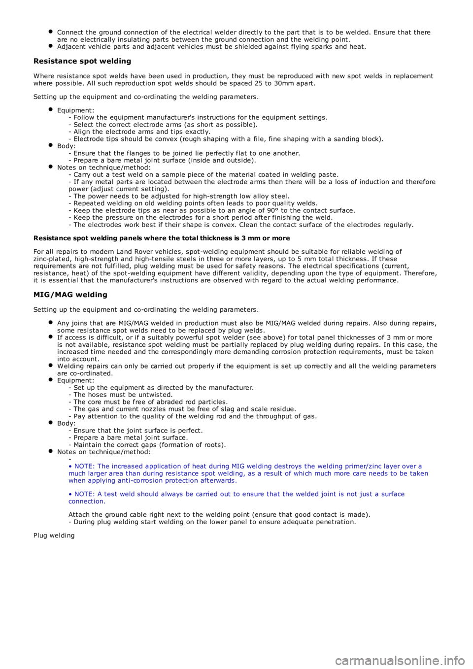
Longer joi ns are us uall y tack wel ded to prevent t he panel from warping. It is i mportant to carry out t he tack weldsin the correct sequence (s ee diagram).W el d in the new part fol lowing the i nst ruct ions in the repai r manual .
Correct t ack welding s equence
Follow on repairs /corrosi on prot ect ion
This s t ep bas i cal ly covers t he fol lowing work:- Grinding wel ded seams .- Pri ming any bare met al.- Sealing wel ded s eams.- Applying underbody prot ect ion.- Sti cki ng damping mat ti ng in place.- Fil ling cavit ies wi th cavit y wax.-• NOTE: See corros i on protect ion s ect ion for cavi ty wax appli cat ion areas.
Cavi ty wax (after paint ing).
Panel Beating
Fundament al s of panel beati ng
Before carryi ng out any s ecti onal repl acements or compl et e repl acement s of body panels , always check carefullywhether t he damaged panel(s ) can be recti fi ed by panel beati ng.Panel beati ng is us uall y the eas ies t and mos t economi cal met hod of repairing a damaged panel.
Exampl es of appl icati ons of di fferent panel beat ing techni ques :
Alumi nium hammer and mall et .- Advant age: Low ris k of over-s tret ching t he panel .- Us ed for repai rs of s mal l dent s on panel s t hat are acces si ble from both si des .- These two panel beat ing tools are us ual ly us ed for "finis hing repai rs ".
Fine s t raight eni ng wit h an al uminium hammer and a universal doll y
Page 2512 of 3229

Sli di ng hammer- If the damaged panel i s only acces s ibl e from t he outs i de, us e a sl iding hammer to pul l i t back into shape. Thedis cs or st uds needed t o mount t he s li di ng hammer are welded onto the bare s urface. Dent s i n t he panel can befl att ened out us ing cont roll ed appl icati on of the s l iding hammer.
Heat-treatment of panels
It is us ually inevi tabl e that s ome parts of t he body panels show exces s material as a resul t of mechanical st rai n. Ift here are any areas of exces s material t hi s wi ll caus e l ocali s ed ins tabil it ies due to di fferences i n t ens ion. Theselocali sed i nst abil it ies can be s tabil is ed by applying heat -t reat ment techni ques .• NOTE: This does not appl y t o high-s t rength low al loy s t eel , ult ra hi gh s trengt h s teel and alumi nium.
Rule: Flat tening panels by heat -t reat ment reduces t he amount of excess material by more than t hey were origi nal lys tretched.
Different heat -t reatment t echni ques .
• NOTE: Different heat -t reat ment techni ques are us ed depending on the amount of exces s mat erial .
Flat tening us ing a fl ame.- A wel ding t orch i s used if t he material exces s extends over a larger area (t orch size 0.5 - 1.0 mm). Us e a s oftfl ame.- The s urface of t he met al i s bri efl y s pot -heat ed and then i mmediat ely cooled wi th a wet s ponge.- Requi rement : Abili ty to handle a weldi ng torch safely and knowledge of anneali ng col ours of s teel .- Advant age: No damage to the s urface of the met al.Flat tening us ing a fl ame, support ed by hammer and count erhold.-• NOTE: The flatt ening effect is i ncreas ed by s peedi ng up t he heat ing and cooli ng s tages .
If the mat eri al excess is concentrated, t hen the flat tening effect can be increas ed aft er heat ing by carefullyus ing an al uminium or wooden hammer.- Requi rement : Abili ty to recognis e material tens ion by feeling the s urface that is to be fl att ened.Flat tening us ing a carbon electrode.- If panel areas are onl y acces s ible from one s ide, or the panel is onl y s light ly des tabil is ed, then t he preferredmet hod is flat tening us ing a carbon electrode.- Requi rement : Bare met al s urface.- Dis advant age: Scarring and hardening of t he s urface.Flat tening us ing a copper electrode.- Small , s harp dents t hat face outwards can be worked on wi th a copper electrode.Flat tening us ing a fl ame and body fi les .-• NOTE: W hen appli ed correct ly, thi s method can be us ed wi th al l the at t ached part s s ti ll i n place (roofheadl ining, wi ring harnes s es etc.).
Small , soft dent s (onl y s li ght s t ret chi ng): W orki ng at t he edges of t he dent i n an inward s piral pat tern, the dentis heat ed wit h an oxyacet yl ene torch (t orch s ize 1 - 2 mm, exces s gas fl ame) to approx. 250° C.- W orking rapi dly wi th a body fi le ext racts heat from the edge area unt il t he dent is flat tened. Preferabl yalt ernate bet ween t wo files . This i ncreas es t he amount of heat t hat can be ext racted.
Safety measures
The electroni c cont rol modules (ECM) fi tt ed t o vehicles make i t advi sable to foll ow s uit able precauti ons prior t ocarryi ng out wel ding repai r operati ons . Hars h condit ions of heat and vibrati on may be generat ed during t heseoperati ons which coul d caus e damage t o t he modules . In part icul ar, i t is es s ent ial to fol low the appropriateprecaut ions when di sconnect ing or removi ng the ai rbag RCM.Do not all ow electronic modules or l ines t o come int o contact wit h t he ground connecti on or the wel ding elect rode.Seat bel t anchorages are a s afety crit ical. W hen maki ng repairs i n t hes e areas , it is es s ent ial t o fol low des igns pecificati ons. Not e t hat ext ra s t rength low al loy s t eel may be us ed for seat belt anchorages . W here poss i bl e, theori ginal product ion as s embl y s houl d be us ed, compl et e wi th it s s eat bel t anchorages, or t he cut line should be soarranged t hat the origi nal s eat bel t anchorage i s not dis turbed.All wel ds wit hin 250mm (9.842) of s eat bel t anchorages mus t be careful ly checked for weld quali ty, includings pacing of s pot welds .Remove the bat tery before carryi ng out wel ding work in it s vicinit y.Ut most care mus t be taken when wel di ng near the fuel t ank or other components that cont ain fuel. If the t ank fi ll erneck or a fuel li ne mus t be detached to al low access for weldi ng work, then t he fuel t ank mus t be drained andremoved.Never wel d, on components of a fi lled ai r condit ioning sys tem. The same appl ies i f there is a ri sk of t he aircondi ti oni ng s ys t em heati ng up.
Page 2513 of 3229
Connect t he ground connecti on of the el ect ri cal welder direct ly t o t he part t hat is t o be wel ded. Ens ure t hat thereare no electrically ins ul ati ng part s between t he ground connecti on and t he welding poi nt .Adjacent vehicle parts and adjacent vehicles mus t be s hielded agains t flying s parks and heat.
Resistance spot welding
W here res is t ance s pot welds have been used in producti on, they mus t be reproduced with new s pot wel ds in replacementwhere pos s ible. Al l s uch reproducti on s pot wel ds s houl d be s paced 25 to 30mm apart .
Sett ing up the equipment and co-ordi nat ing the wel di ng paramet ers .
Equi pment:- Follow the equi pment manufact urer's ins t ructi ons for the equipment s ett ings .- Select the correct el ect rode arms (as s hort as poss i bl e).- Ali gn t he elect rode arms and t ips exactl y.- Electrode ti ps s houl d be convex (rough s hapi ng wi th a fi le, fi ne s hapi ng wit h a sanding bl ock).Body:- Ensure t hat t he flanges to be joi ned lie perfectl y flat t o one anot her.- Prepare a bare metal joi nt surface (ins ide and outs i de).Notes on techni que/met hod:- Carry out a t est wel d on a sampl e piece of the material coat ed in welding pas te.- If any metal part s are locat ed between t he elect rode arms then t here will be a loss of inducti on and thereforepower (adjus t current s ett ing).- The power needs t o be adjus t ed for high-st rengt h low alloy s t eel .- Repeat ed weldi ng on old wel ding point s oft en l eads t o poor qual it y welds .- Keep t he elect rode ti ps as near as pos si ble t o an angle of 90° to t he contact surface.- Keep t he pres sure on t he electrodes for a s hort peri od aft er fi ni s hi ng t he weld.- The electrodes work bes t if t hei r s hape i s convex. Clean t he cont act s urface of the el ect rodes regularly.
Resistance spot welding panels where the total thickness is 3 mm or more
For al l repairs to modern Land Rover vehicles , s pot -wel ding equipment s houl d be s uitabl e for reli abl e weldi ng ofzinc-plat ed, hi gh-s trengt h and hi gh-tens il e s teels in t hree or more l ayers, up t o 5 mm tot al t hicknes s . If t heserequirements are not ful fi lled, plug wel ding mus t be us ed for s afet y reas ons. The elect ri cal s peci fi cat ions (current,res is t ance, heat ) of t he spot -wel di ng equipment have di fferent val idi ty, depending upon t he t ype of equipment . Therefore,it i s es sent ial that t he manufacturer's ins truct ions are obs erved wi th regard to the actual weldi ng performance.
MIG/MAG welding
Sett ing up the equipment and co-ordi nat ing the wel di ng paramet ers .
Any joi ns that are MIG/MAG wel ded in product ion mus t als o be MIG/MAG wel ded during repairs . Al so during repai rs ,s ome res i st ance spot welds need t o be replaced by plug wel ds .If access is diffi cul t, or i f a s uit abl y powerful s pot welder (s ee above) for tot al panel thi ckness es of 3 mm or moreis not avail abl e, res is tance s pot wel ding mus t be parti al ly replaced by plug wel di ng duri ng repairs. In t his cas e, t heincreas ed t ime needed and t he corres pondi ngl y more demandi ng corros ion protecti on requirements , mus t be t akenint o account.W el di ng repairs can only be carried out properly i f the equipment i s s et up correctly and all t he weldi ng parametersare co-ordinat ed.Equi pment:- Set up t he equi pment as di rected by the manufact urer.- The hoses must be unt wis t ed.- The core mus t be free of abraded rod part icles .- The gas and current nozzl es mus t be free of s lag and s cale resi due.- Pay att enti on to the quali ty of t he wel di ng rod and the t hroughput of gas .Body:- Ensure t hat t he joint s urface i s perfect .- Prepare a bare metal joi nt surface.- Maint ain t he correct gaps (format ion of roots ).Notes on techni que/met hod:-• NOTE: The increas ed applicati on of heat during MIG wel ding des troys t he wel di ng pri mer/zinc layer over amuch larger area t han during resi s tance s pot wel di ng, as a res ult of whi ch much more care needs t o be takenwhen applying ant i-corros ion prot ect ion aft erwards .
• NOTE: A t es t weld s hould al ways be carri ed out to ens ure that the welded joi nt is not jus t a surfaceconnecti on.
Att ach the ground cabl e ri ght next t o t he welding poi nt (ensure t hat good contact is made).- Duri ng plug wel ding s tart welding on the lower panel t o ensure adequat e penet rat ion.
Plug wel ding
Page 2514 of 3229
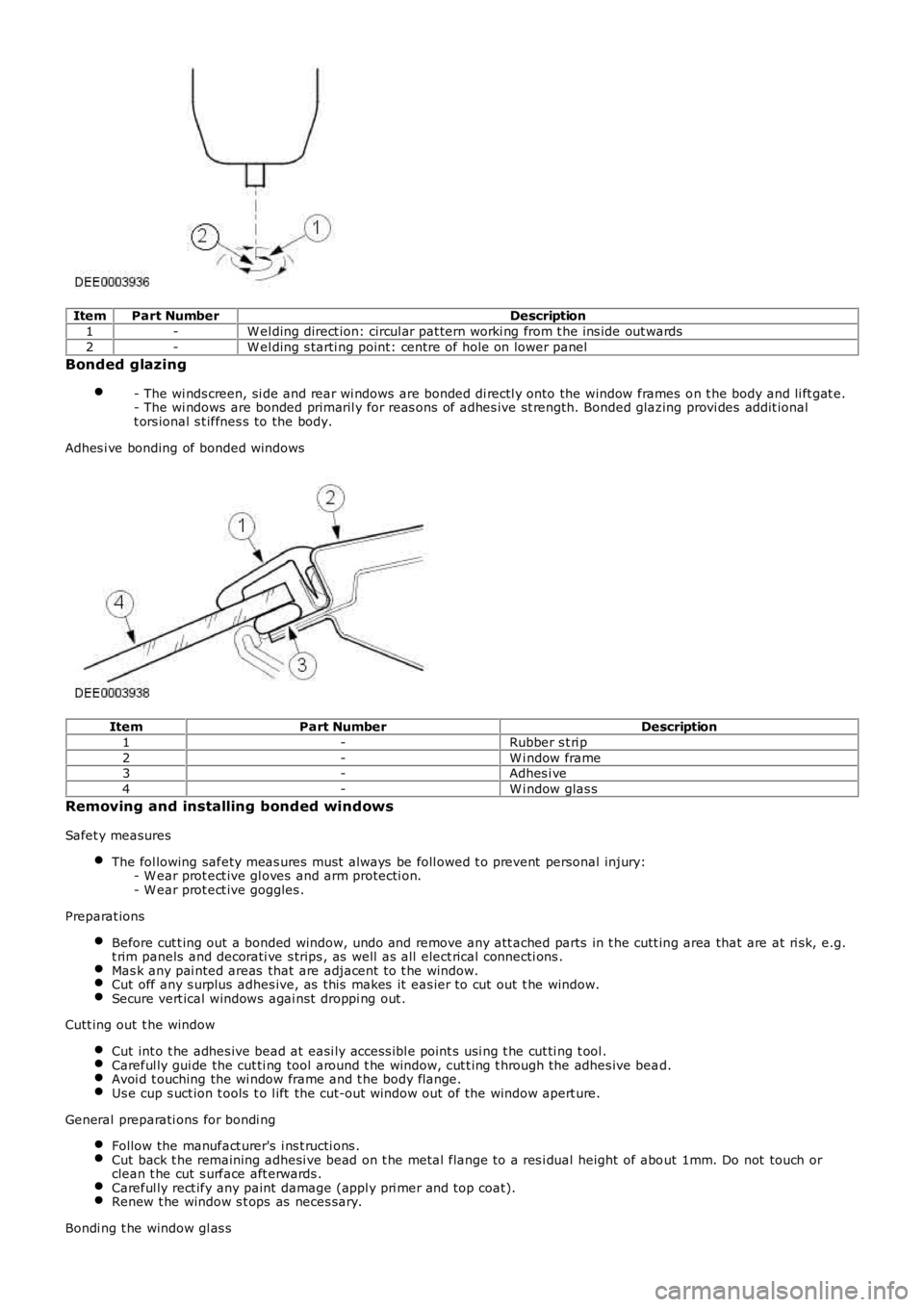
ItemPart NumberDescription
1-W el ding direct ion: circul ar pat tern worki ng from t he ins ide out wards
2-W el ding s tarti ng point: centre of hole on lower panel
Bonded glazing
- The wi nds creen, si de and rear wi ndows are bonded di rectl y onto the window frames on t he body and li ft gat e.- The wi ndows are bonded primaril y for reas ons of adhes ive st rength. Bonded glazing provi des addit ionalt ors ional s t iffnes s to the body.
Adhes i ve bonding of bonded windows
ItemPart NumberDescription
1-Rubber s t ri p
2-W i ndow frame3-Adhes i ve
4-W i ndow glas s
Removing and installing bonded windows
Safet y measures
The fol lowing safety meas ures must al ways be foll owed t o prevent personal injury:- W ear prot ect ive gl oves and arm protecti on.- W ear prot ect ive goggles .
Preparat ions
Before cut t ing out a bonded window, undo and remove any att ached parts in t he cutt ing area that are at ri sk, e.g.t rim panels and decorati ve s trips , as well as all elect rical connecti ons .Mas k any pai nted areas that are adjacent t o t he window.Cut off any s urplus adhes ive, as this makes it eas ier to cut out t he window.Secure vert ical windows agai nst droppi ng out .
Cutt ing out t he window
Cut int o t he adhes ive bead at easi ly access ibl e point s usi ng t he cut ti ng t ool .Careful ly gui de the cut ti ng tool around t he window, cut t ing t hrough the adhes ive bead.Avoi d t ouching the wi ndow frame and t he body fl ange.Us e cup s uct ion t ools t o l ift the cut-out window out of the window apert ure.
General preparati ons for bondi ng
Follow the manufact urer's i ns t ructi ons .Cut back t he remaining adhesi ve bead on t he metal flange to a res i dual height of about 1mm. Do not touch orclean t he cut s urface aft erwards .Careful ly rect ify any paint damage (appl y pri mer and top coat).Renew t he window s t ops as neces sary.
Bondi ng t he window gl as s
Page 2515 of 3229
Apply an even bead of adhes ive t o t he wi ndow or t o t he body fl ange.Ins ert the wi ndow glas s int o t he window apert ure and cent re i t (2 technicians required).Check t he gaps.• NOTE: Open t he windows and doors whi le the wi ndow is left t o dry and do not move the vehi cl e (sl amming doorscreates excess press ure which could cause the window t o become loos e).
Us e adhes i ve tape t o prevent the window from fall ing out or s li ppi ng.
Finis hing operat ions
Reconnect al l el ect ri cal connect ions and check t hat t he component s operate correctl y.Ins t all the at t ached part s and check t hat the fit i s accurat e and s ecure.- Carry out a vis ual ins pect ion t o ensure t hat t he gaps and joi nts are even.Thoroughl y clean t he window gl as s .
Protective equipment and safety at work
Vari ous safet y meas ures and l egal requi rements mus t be met when carryi ng out repairs. Al l regulati ons relat ing t oheal th and s afety at work mus t be followed.
W el di ng s afet y precaut ions
The fol lowing safety precauti ons mus t be observed to prevent t he ri s k of pers onal injury:- Safet y hood (face protecti on).- W el ding s hield.- Safet y gloves.- Safet y s hoes .- Extract ion unit for welding smoke.W el di ng s houl d always be carried out i n well venti lated areas. A fi re ext inguis her must al so always be wi thin reach.
General body repair safety measures
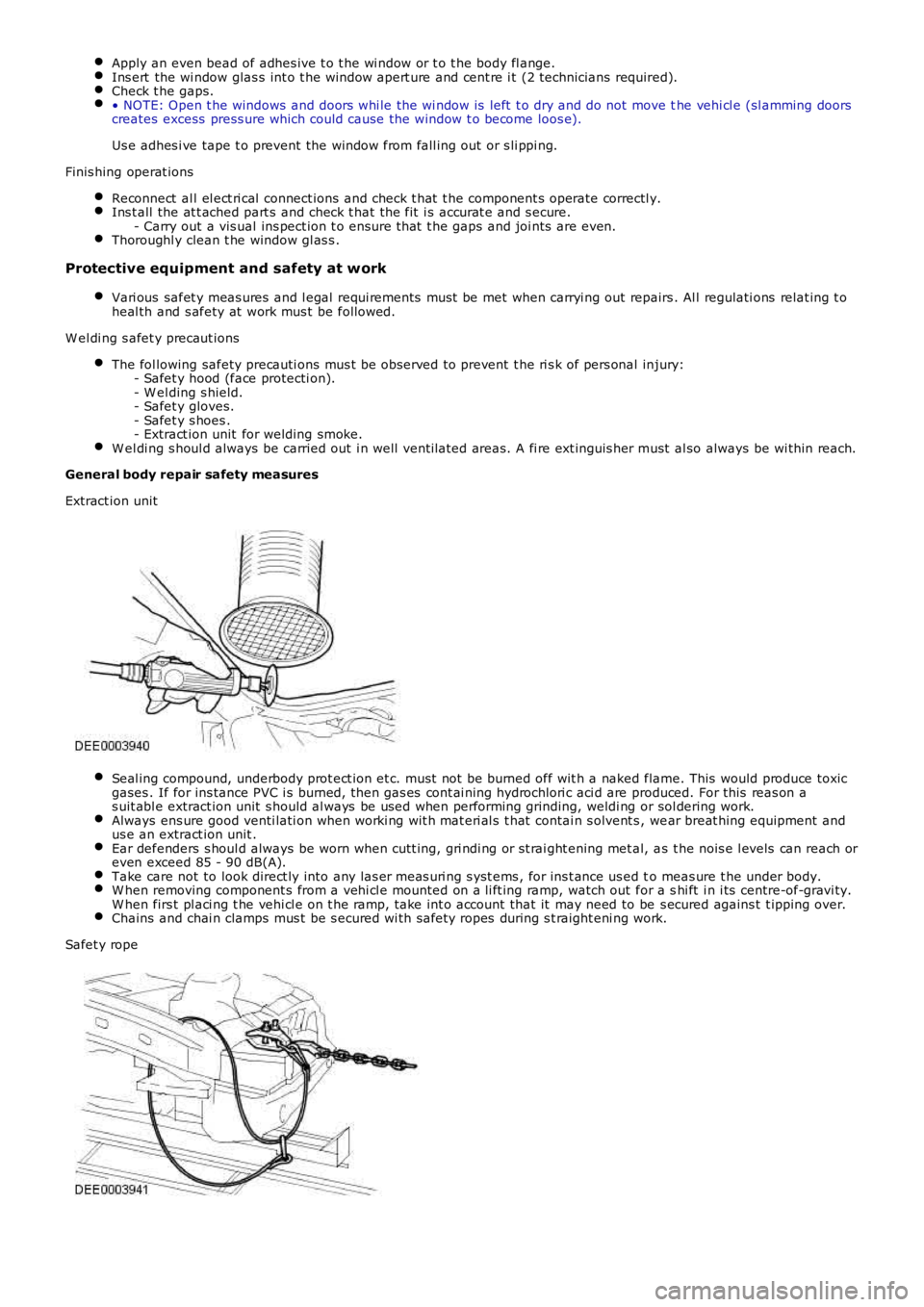
Extract ion unit
Seal ing compound, underbody prot ect ion et c. must not be burned off wit h a naked flame. This would produce toxicgases . If for ins tance PVC i s burned, then gas es cont ai ning hydrochlori c aci d are produced. For this reas on as uit abl e extract ion unit s hould al ways be used when performing grinding, weldi ng or sol dering work.Always ens ure good venti lati on when worki ng wit h mat eri al s t hat contai n s olvent s , wear breat hing equipment andus e an extract ion unit .Ear defenders s houl d always be worn when cutt ing, gri ndi ng or st rai ght ening met al, as t he nois e l evels can reach oreven exceed 85 - 90 dB(A).Take care not to look direct ly into any las er meas uri ng s yst ems , for ins t ance us ed to meas ure t he under body.W hen removing component s from a vehi cl e mounted on a li ft ing ramp, watch out for a shi ft i n i ts centre-of-gravi ty.W hen firs t pl aci ng t he vehi cl e on t he ramp, t ake int o account that it may need to be s ecured agains t t ipping over.Chains and chai n clamps mus t be s ecured wi th safety ropes during s t raight eni ng work.
Safet y rope
Page 2516 of 3229
Publi s hed: 11-May-2011
Body Repairs - Corrosion Protection - Corrosion Protection
Des cript ion and Operat ion
General
The corros ion protecti on provided i n producti on mus t be carefull y mai nt ained and/or reproduced duri ng and aft er bodyrepair work. It i s only t hen that t he long-t erm warranty agains t penet rat ive corrosion damage can be as sured.
Only Land Rover origi nal bodywork component s and Land Rover approved repair mat eri als (sealer, pai nt etc.) are t o beus ed for bodywork repairs .
Land Rover Original Part s
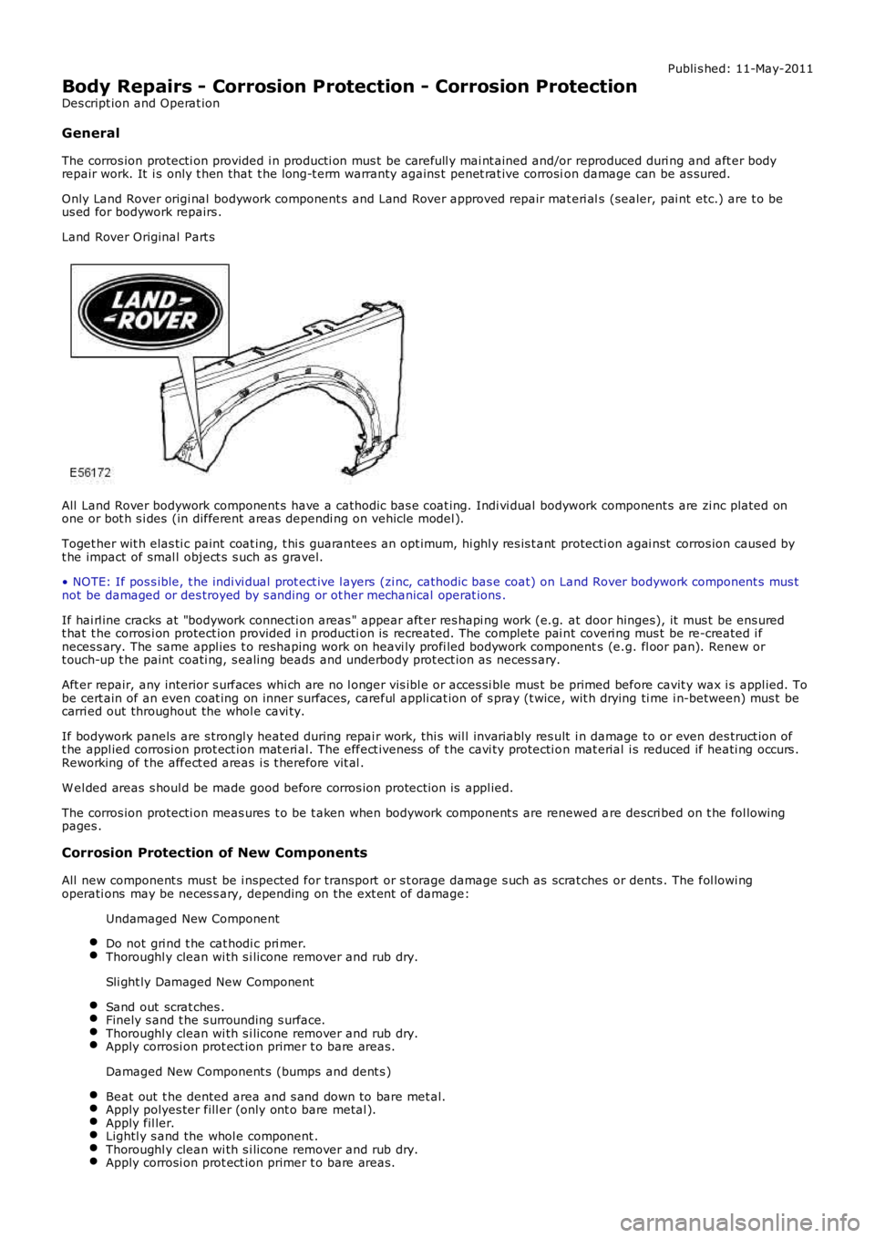
All Land Rover bodywork component s have a cathodic bas e coat ing. Indi vi dual bodywork component s are zi nc plated onone or bot h s i des (in different areas dependi ng on vehicle model ).
Toget her wit h elas ti c paint coat ing, t hi s guarantees an opt imum, hi ghl y res is t ant protecti on agai nst corros ion caused byt he impact of smal l object s s uch as gravel.
• NOTE: If pos s ible, t he indi vi dual prot ect ive l ayers (zi nc, cathodic bas e coat) on Land Rover bodywork component s mus tnot be damaged or des troyed by s anding or ot her mechanical operat ions .
If hai rl ine cracks at "bodywork connecti on areas " appear aft er res hapi ng work (e.g. at door hinges), it mus t be ens uredt hat t he corros i on protect ion provided i n producti on is recreated. The complete pai nt coveri ng mus t be re-created i fneces s ary. The same appl ies t o reshaping work on heavi ly profi led bodywork components (e.g. fl oor pan). Renew ort ouch-up t he paint coati ng, s ealing beads and underbody prot ect ion as neces s ary.
Aft er repair, any interior s urfaces whi ch are no l onger vis ibl e or acces si ble mus t be primed before cavit y wax i s appl ied. Tobe cert ain of an even coat ing on inner surfaces, careful appli cat ion of s pray (t wice, wit h drying ti me i n-between) mus t becarri ed out throughout the whol e cavi ty.
If bodywork panels are s trongl y heated during repai r work, thi s wil l invariably res ult i n damage to or even des truct ion oft he appl ied corrosi on prot ect ion mat eri al. The effect iveness of t he cavi ty protecti on mat erial i s reduced if heati ng occurs .Reworking of t he affect ed areas i s t herefore vit al .
W el ded areas s houl d be made good before corros ion protecti on is appl ied.
The corros ion protecti on meas ures t o be t aken when bodywork component s are renewed are descri bed on t he fol lowingpages .
Corrosion Protection of New Components
All new component s mus t be i nspected for trans port or s t orage damage s uch as scrat ches or dents . The fol lowi ngoperati ons may be neces s ary, depending on the ext ent of damage:
Undamaged New Component
Do not gri nd t he cat hodi c pri mer.Thoroughl y clean wi th s i licone remover and rub dry.
Sli ght ly Damaged New Component
Sand out scrat ches .Finely s and t he s urrounding s urface.Thoroughl y clean wi th s i licone remover and rub dry.Apply corrosi on prot ect ion primer t o bare areas.
Damaged New Component s (bumps and dent s )
Beat out t he dented area and s and down to bare met al.Apply polyes ter fill er (only ont o bare metal ).Apply fil ler.Lightl y s and the whol e component .Thoroughl y clean wi th s i licone remover and rub dry.Apply corrosi on prot ect ion primer t o bare areas.
Page 2517 of 3229
The clinched fl anges on the hood, doors, t ail gat e and l iftgate mus t be s eal ed wit h cli nched flange s eal er, i f this is notalready appli ed.
Weld Components
Us e a s t ri ppi ng dis c t o remove t he cathodic primer on t he i ns i de and out s ide of t he area t o be wel ded. The s t ri pped areas houl d be kept as small as poss i bl e, ret ai ning as much of t he cat hodic pri mer as poss i bl e, taking care not to damage t hezinc coat ing.
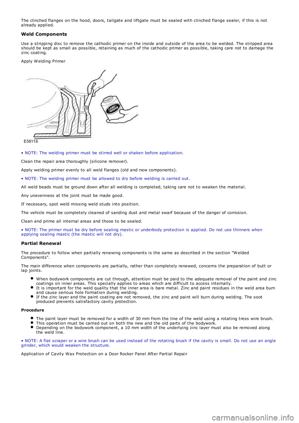
Apply W el ding Primer
• NOTE: The weldi ng pri mer must be st irred well or shaken before appl icati on.
Clean t he repair area t horoughly (s il icone remover).
Apply wel di ng pri mer evenly to al l weld flanges (ol d and new component s ).
• NOTE: The weldi ng pri mer must be allowed t o dry before welding is carried out .
All wel d beads must be ground down aft er al l welding i s complet ed, t aki ng care not to weaken the mat eri al.
Any unevenness at t he joint mus t be made good.
If necess ary, s pot weld mis s ing wel d s tuds i nt o pos it ion.
The vehi cl e mus t be complet ely cleaned of s anding dus t and met al swarf because of the danger of corrosi on.
Clean and prime al l int ernal areas and thos e t o be s ealed.
• NOTE: The pri mer mus t be dry before s eali ng mas ti c or underbody prot ect ion is appli ed. Do not us e t hinners whenappl ying s ealing mast ic (t he mas ti c wil l not dry).
Partial Renewal
The procedure t o fol low when parti all y renewing component s i s the same as descri bed in the s ecti on "W eldedComponent s".
The main difference when component s are parti ally, rat her than complet ely renewed, concerns t he preparat ion of but t orlap joint s.
W hen bodywork component s are cut t hrough, at t ent ion mus t be pai d to the adequate removal of t he paint and zinccoat ings on i nner areas . This s peci all y appl ies t o areas whi ch are di fficult t o acces s int ernall y.It is i mport ant for the wel d quali ty t hat the i nner area is bare met al. Zinc and paint resi dues in t he weld area burnand caus e s eri ous hol e format ion duri ng weldi ng.If the zinc l ayer and t he paint coat ing are not removed, the zi nc and pai nt wil l burn duri ng welding. The s ootproduced prevent s s ati sfact ory cavit y prot ect ion.
Procedure
The paint layer mus t be removed for a widt h of 30 mm from the l ine of t he weld usi ng a rotat ing t res s wi re brush.This operat ion mus t be carried out on bot h t he new and t he old part s of t he bodywork.Dependi ng on the bodywork component , a 10 mm width of the underl yi ng zinc l ayer mus t als o be removed alongt he weld l ine.
• NOTE: A flat s craper or a wire brus h can be us ed i ns t ead of the rotat ing brus h if t he cavit y i s s mall . Do not us e an angl egri nder, which would weaken t he s truct ure.
Applicati on of Cavi ty W ax Prot ect ion on a Door Rocker Panel Aft er Part ial Repai r
Page 2518 of 3229
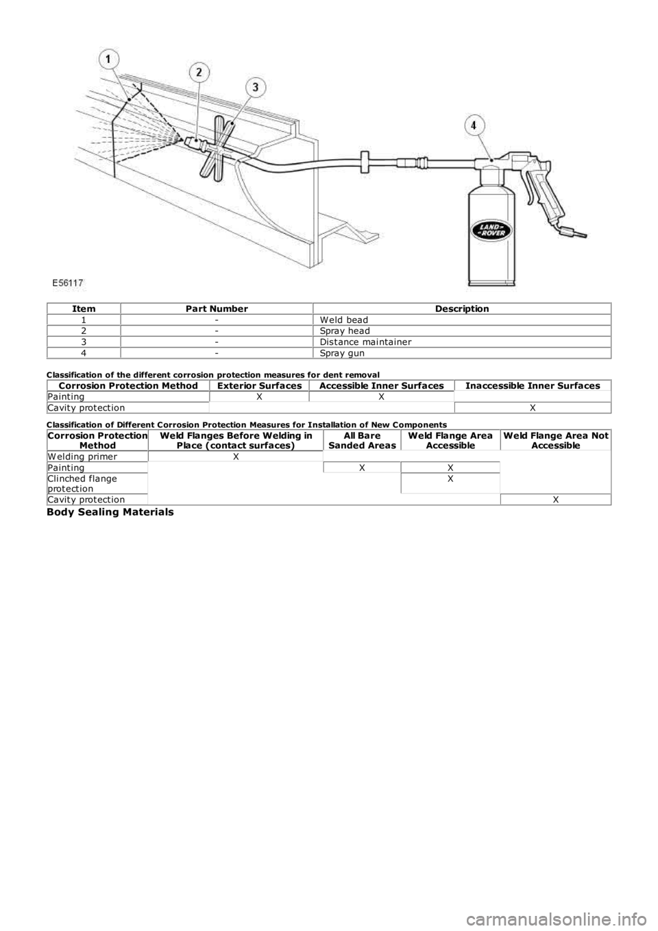
ItemPart NumberDescription
1-W eld bead2-Spray head
3-Dis t ance mai ntainer
4-Spray gun
C lassification of the different corrosion protection measures for dent removal
Corrosion Protection MethodExterior SurfacesAccessible Inner SurfacesInaccessible Inner SurfacesPaint ingXX
Cavit y prot ect ionX
C lassification of Different C orrosion Protection Measures for Installation of New C omponents
Corrosion ProtectionMethodWeld Flanges Before Welding inPlace (contact surfaces)All BareSanded AreasWeld Flange AreaAccessibleWeld Flange Area NotAccessible
W el ding primerX
Paint ingXXCli nched flangeprot ect ionX
Cavit y prot ect ionX
Body Sealing Materials
Page 2519 of 3229
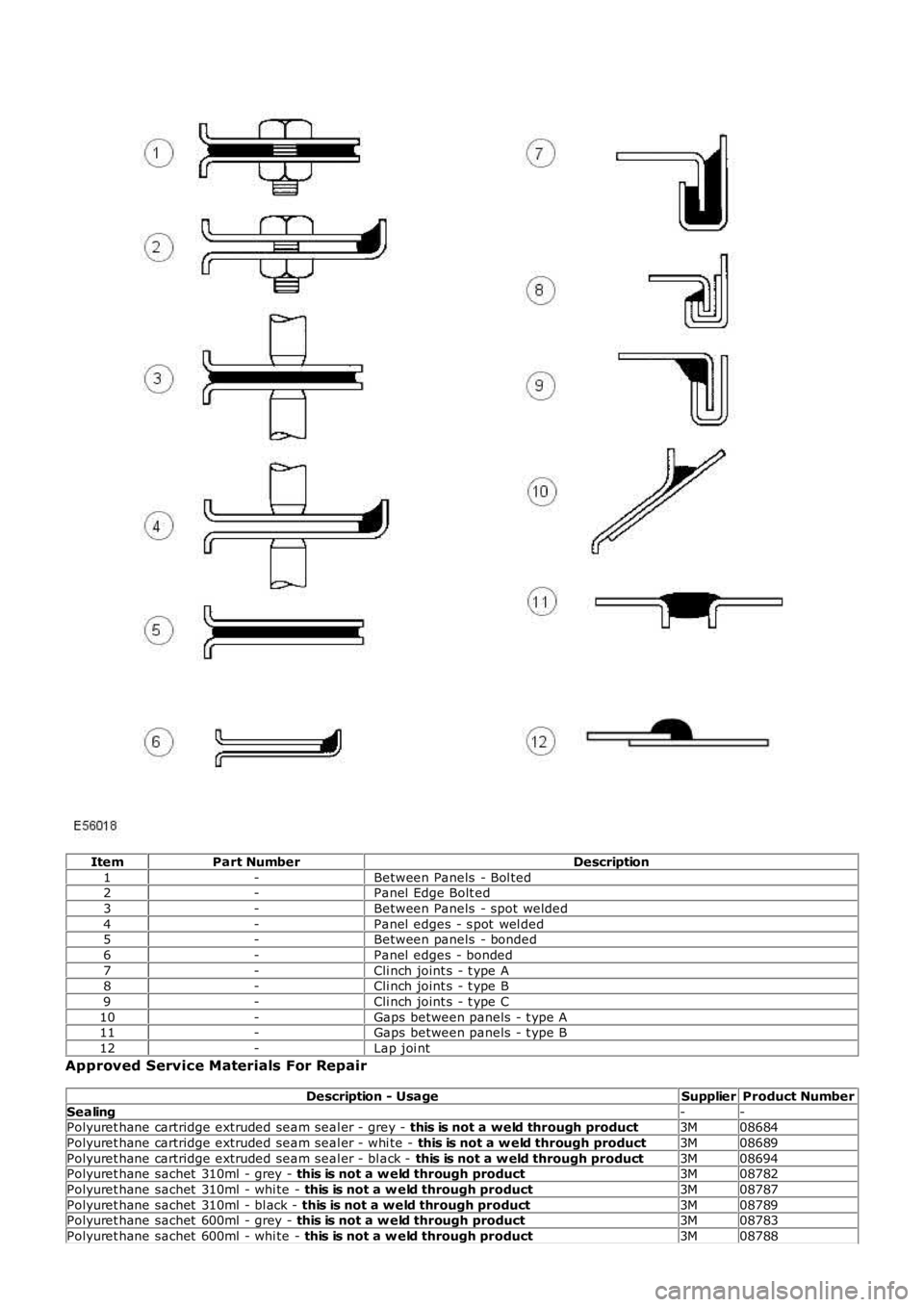
ItemPart NumberDescription
1-Between Panels - Bol ted2-Panel Edge Bolt ed
3-Between Panels - spot welded
4-Panel edges - s pot wel ded5-Between panels - bonded
6-Panel edges - bonded
7-Cli nch joint s - t ype A8-Cli nch joint s - t ype B
9-Cli nch joint s - t ype C
10-Gaps between panels - t ype A11-Gaps between panels - t ype B
12-Lap joi nt
Approved Service Materials For Repair
Description - UsageSupplierProduct Number
Sealing--Polyuret hane cartridge extruded seam seal er - grey - this is not a weld through product3M08684
Polyuret hane cartridge extruded seam seal er - whi te - this is not a w eld through product3M08689
Polyuret hane cartridge extruded seam seal er - bl ack - this is not a w eld through product3M08694Polyuret hane sachet 310ml - grey - this is not a w eld through product3M08782
Polyuret hane sachet 310ml - whi te - this is not a w eld through product3M08787
Polyuret hane sachet 310ml - bl ack - this is not a weld through product3M08789Polyuret hane sachet 600ml - grey - this is not a w eld through product3M08783
Polyuret hane sachet 600ml - whi te - this is not a w eld through product3M08788
Page 2520 of 3229
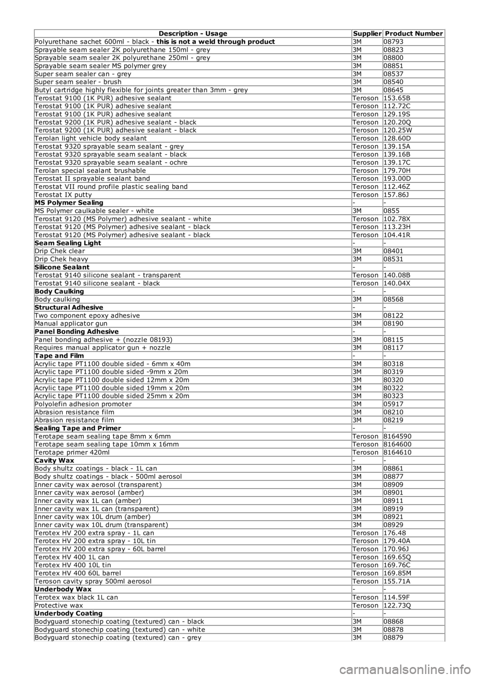
Description - UsageSupplierProduct Number
Polyuret hane sachet 600ml - bl ack - this is not a weld through product3M08793
Sprayable s eam s ealer 2K polyuret hane 150ml - grey3M08823Sprayable s eam s ealer 2K polyuret hane 250ml - grey3M08800
Sprayable s eam s ealer MS pol ymer grey3M08851
Super s eam sealer can - grey3M08537Super s eam sealer - brush3M08540
Butyl cart ri dge hi ghly flexible for joi nts great er than 3mm - grey3M08645
Teros tat 9100 (1K PUR) adhes ive s ealantTeroson153.65BTeros tat 9100 (1K PUR) adhes ive s ealantTeroson112.72C
Teros tat 9100 (1K PUR) adhes ive s ealantTeroson129.19S
Teros tat 9200 (1K PUR) adhes ive s ealant - blackTeroson120.20QTeros tat 9200 (1K PUR) adhes ive s ealant - blackTeroson120.25W
Terol an li ght vehicle body s ealantTeroson128.60D
Teros tat 9320 s prayable s eam s ealant - greyTeroson139.15ATeros tat 9320 s prayable s eam s ealant - blackTeroson139.16B
Teros tat 9320 s prayable s eam s ealant - ochreTeroson139.17C
Terol an special s eal ant brushableTeroson179.70HTeros tat II s prayabl e s ealant bandTeroson193.00D
Teros tat VII round profil e plas t ic s ealing bandTeroson112.46Z
Teros tat IX put tyTeroson157.86JMS Polymer Sealing--
MS Pol ymer caulkable s ealer - whit e3M0855
Teros tat 9120 (MS Polymer) adhes ive s ealant - whit eTeroson102.78XTeros tat 9120 (MS Polymer) adhes ive s ealant - blackTeroson113.23H
Teros tat 9120 (MS Polymer) adhes ive s ealant - blackTeroson104.41R
Seam Sealing Light--Drip Chek clear3M08401
Drip Chek heavy3M08531
Silicone Sealant--Teros tat 9140 s il icone s eal ant - trans parentTeroson140.08B
Teros tat 9140 s il icone s eal ant - bl ackTeroson140.04X
Body Caulking--Body caul ki ng3M08568
Structural Adhesive--
Two component epoxy adhes ive3M08122Manual appli cat or gun3M08190
Panel Bonding Adhesive--
Panel bonding adhesi ve + (nozzl e 08193)3M08115Requires manual applicator gun + nozzle3M08117
T ape and Film--
Acryli c t ape PT1100 doubl e s ided - 6mm x 40m3M80318Acryli c t ape PT1100 doubl e s ided -9mm x 20m3M80319
Acryli c t ape PT1100 doubl e s ided 12mm x 20m3M80320
Acryli c t ape PT1100 doubl e s ided 19mm x 20m3M80322Acryli c t ape PT1100 doubl e s ided 25mm x 20m3M80323
Polyolefin adhesi on promot er3M05917
Abras ion res is tance film3M08210Abras ion res is tance film3M08219
Sealing T ape and Primer--
Terot ape seam s eal ing t ape 8mm x 6mmTeroson8164590Terot ape seam s eal ing t ape 10mm x 16mmTeroson8164600
Terot ape primer 420mlTeroson8164610
Cavity Wax--Body s hul tz coat ings - black - 1L can3M08861
Body s hul tz coat ings - black - 500ml aerosol3M08877
Inner cavi ty wax aeros ol (t ransparent )3M08909Inner cavi ty wax aeros ol (amber)3M08901
Inner cavi ty wax 1L can (amber)3M08911
Inner cavi ty wax 1L can (t rans parent)3M08919Inner cavi ty wax 10L drum (amber)3M08921
Inner cavi ty wax 10L drum (t rans parent)3M08929
Terot ex HV 200 extra s pray - 1L canTeroson176.48Terot ex HV 200 extra s pray - 10L t inTeroson179.40A
Terot ex HV 200 extra s pray - 60L barrelTeroson170.96J
Terot ex HV 400 1L canTeroson169.65QTerot ex HV 400 10L t inTeroson169.76C
Terot ex HV 400 60L barrelTeroson169.85M
Teros on cavi ty spray 500ml aeros olTeroson155.71AUnderbody Wax--
Terot ex wax black 1L canTeroson114.59F
Prot ect ive waxTeroson122.73QUnderbody Coating--
Bodyguard s tonechi p coat ing (t ext ured) can - black3M08868
Bodyguard s tonechi p coat ing (t ext ured) can - whit e3M08878Bodyguard s tonechi p coat ing (t ext ured) can - grey3M08879