LEXUS LS430 2003 Factory Owners Manual
LS430 2003
LEXUS
LEXUS
https://www.carmanualsonline.info/img/36/57050/w960_57050-0.png
LEXUS LS430 2003 Factory Owners Manual
Page 1572 of 4500
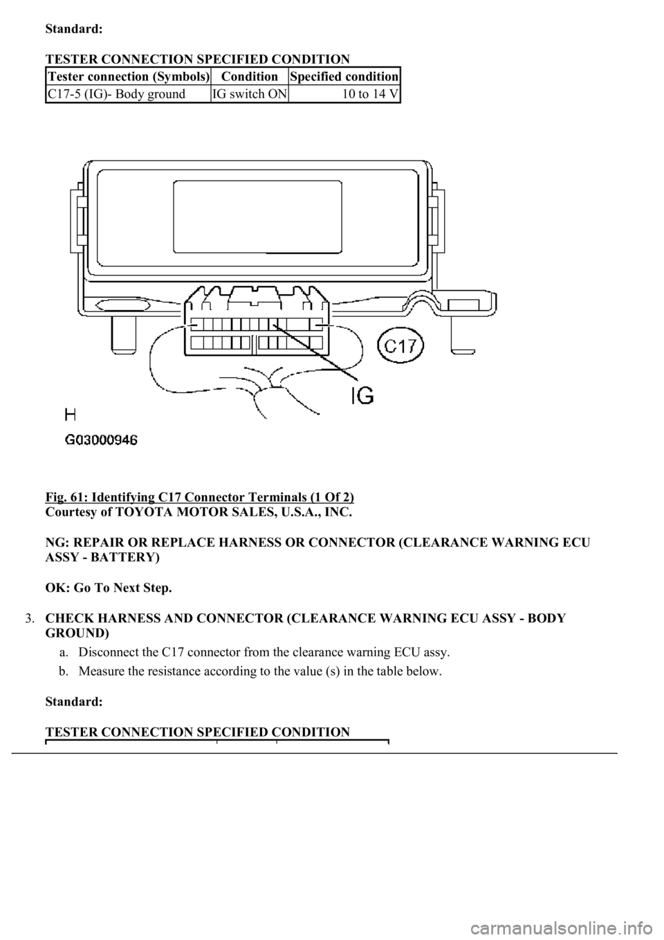
Standard:
TESTER CONNECTION SPECIFIED CONDITION
Fig. 61: Identifying C17 Connector Terminals (1 Of 2)
Courtesy of TOYOTA MOTOR SALES, U.S.A., INC.
NG: REPAIR OR REPLACE HARNESS OR CONNECTOR (CLEARANCE WARNING ECU
ASSY - BATTERY)
OK: Go To Next Step.
3.CHECK HARNESS AND CONNECTOR (CLEARANCE WARNING ECU ASSY - BODY
GROUND)
a. Disconnect the C17 connector from the clearance warning ECU assy.
b. Measure the resistance according to the value (s) in the table below.
Standard:
TESTER CONNECTION SPECIFIED CONDITION
Tester connection (Symbols)ConditionSpecified condition
C17-5 (IG)- Body groundIG switch ON10 to 14 V
Page 1578 of 4500
Fig. 67: Identifying Outer Mirror Switch Assy Connector Terminals
Courtesy of TOYOTA MOTOR SALES, U.S.A., INC.
NG: REPLACE OUTER MIRROR SWITCH ASSY
OK: REPAIR OR REPLACE HARNESS OR CONNECTOR (CLEARANCE WARNING ECU
ASSY - BATTERY)
CIRCUIT DESCRIPTION
The clearance warning ECU assy receives the ultrasonic sensor signal to sound the clearance warning buzzer.
WIRING DIAGRAM
Page 1605 of 4500
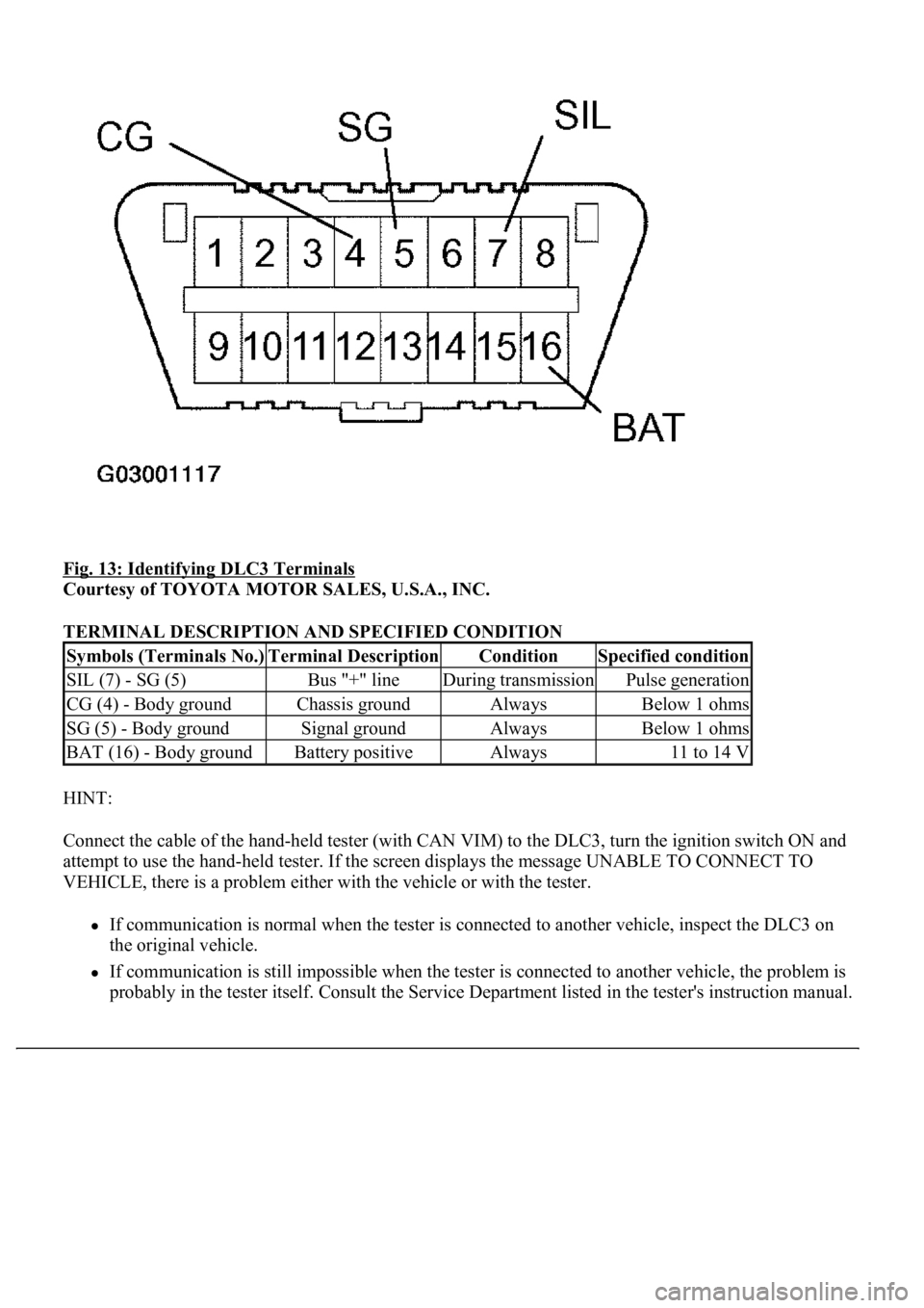
Fig. 13: Identifying DLC3 Terminals
Courtesy of TOYOTA MOTOR SALES, U.S.A., INC.
TERMINAL DESCRIPTION AND SPECIFIED CONDITION
HINT:
Connect the cable of the hand-held tester (with CAN VIM) to the DLC3, turn the ignition switch ON and
attempt to use the hand-held tester. If the screen displays the message UNABLE TO CONNECT TO
VEHICLE, there is a problem either with the vehicle or with the tester.
If communication is normal when the tester is connected to another vehicle, inspect the DLC3 on
the original vehicle.
If communication is still impossible when the tester is connected to another vehicle, the problem is
probably in the tester itself. Consult the Service Department listed in the tester's instruction manual.
Symbols (Terminals No.)Terminal DescriptionConditionSpecified condition
SIL (7) - SG (5)Bus "+" lineDuring transmissionPulse generation
CG (4) - Body groundChassis groundAlwaysBelow 1 ohms
SG (5) - Body groundSignal groundAlwaysBelow 1 ohms
BAT (16) - Body groundBattery positiveAlways11 to 14 V
Page 1606 of 4500
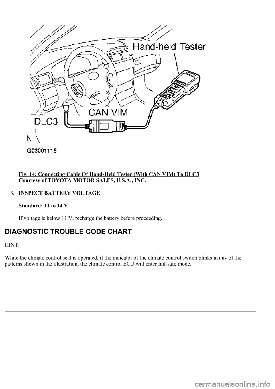
Fig. 14: Connecting Cable Of Hand-Held Tester (With CAN VIM) To DLC3
Courtesy of TOYOTA MOTOR SALES, U.S.A., INC.
3.INSPECT BATTERY VOLTAGE
Standard: 11 to 14 V
If voltage is below 11 V, recharge the battery before proceeding.
HINT:
While the climate control seat is operated, if the indicator of the climate control switch blinks in any of the
patterns shown in the illustration, the climate control ECU will enter fail-safe mode.
Page 1669 of 4500
NG: REPAIR OR REPLACE AIR DUCT
OK: REPLACE SEAT CLIMATE CONTROL CONTROLLER (SEATBACK OR SEAT
CUSHION)
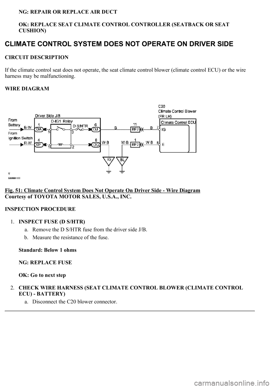
CIRCUIT DESCRIPTION
If the climate control seat does not operate, the seat climate control blower (climate control ECU) or the wire
harness may be malfunctioning.
WIRE DIAGRAM
Fig. 51: Climate Control System Does Not Operate On Driver Side
- Wire Diagram
Courtesy of TOYOTA MOTOR SALES, U.S.A., INC.
INSPECTION PROCEDURE
1.INSPECT FUSE (D S/HTR)
a. Remove the D S/HTR fuse from the driver side J/B.
b. Measure the resistance of the fuse.
Standard: Below 1 ohms
NG: REPLACE FUSE
OK: Go to next step
2.CHECK WIRE HARNESS (SEAT CLIMATE CONTROL BLOWER (CLIMATE CONTROL
ECU) - BATTERY)
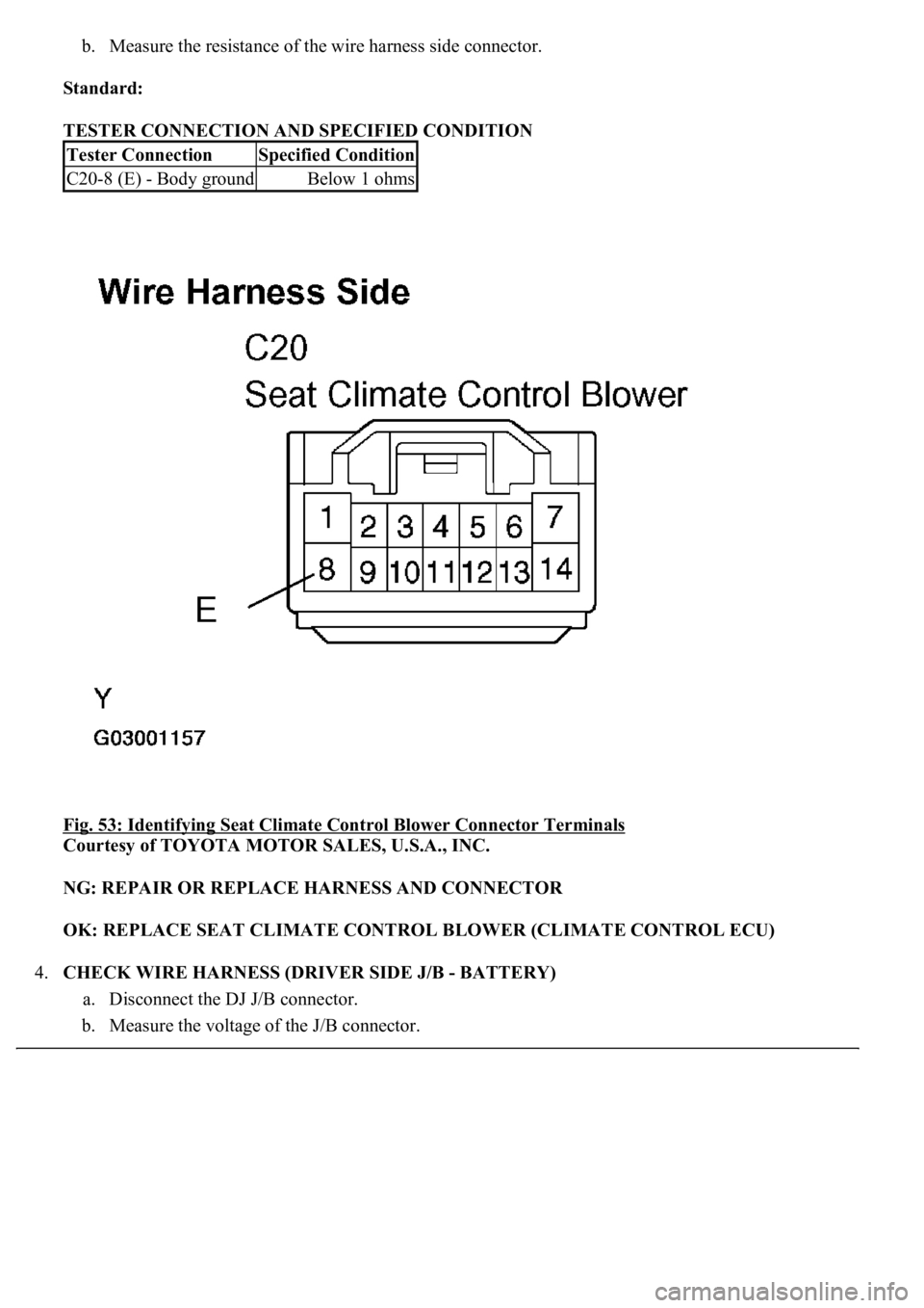
a. Disconnect the C20 blower connector.
Page 1671 of 4500
b. Measure the resistance of the wire harness side connector.
Standard:
TESTER CONNECTION AND SPECIFIED CONDITION
Fig. 53: Identifying Seat Climate Control Blower Connector Terminals
Courtesy of TOYOTA MOTOR SALES, U.S.A., INC.
NG: REPAIR OR REPLACE HARNESS AND CONNECTOR
OK: REPLACE SEAT CLIMATE CONTROL BLOWER (CLIMATE CONTROL ECU)
4.CHECK WIRE HARNESS (DRIVER SIDE J/B - BATTERY)
a. Disconnect the DJ J/B connector.
b. Measure the voltage of the J/B connector.
Tester ConnectionSpecified Condition
C20-8 (E) - Body groundBelow 1 ohms
Page 1672 of 4500
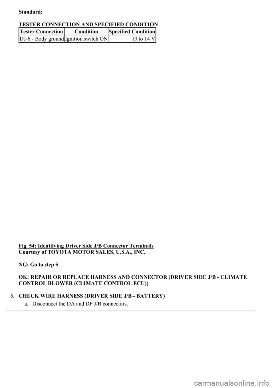
Standard:
TESTER CONNECTION AND SPECIFIED CONDITION
Fig. 54: Identifying Driver Side J/B Connector Terminals
Courtesy of TOYOTA MOTOR SALES, U.S.A., INC.
NG: Go to step 5
OK: REPAIR OR REPLACE HARNESS AND CONNECTOR (DRIVER SIDE J/B - CLIMATE
CONTROL BLOWER (CLIMATE CONTROL ECU))
5.CHECK WIRE HARNESS (DRIVER SIDE J/B - BATTERY)
a. Disconnect the DA and DF J/B connectors.
Tester ConnectionConditionSpecified Condition
DJ-6 - Body groundIgnition switch ON10 to 14 V
Page 1676 of 4500
NG: REPAIR OR REPLACE HARNESS AND CONNECTOR
OK: Go to next step
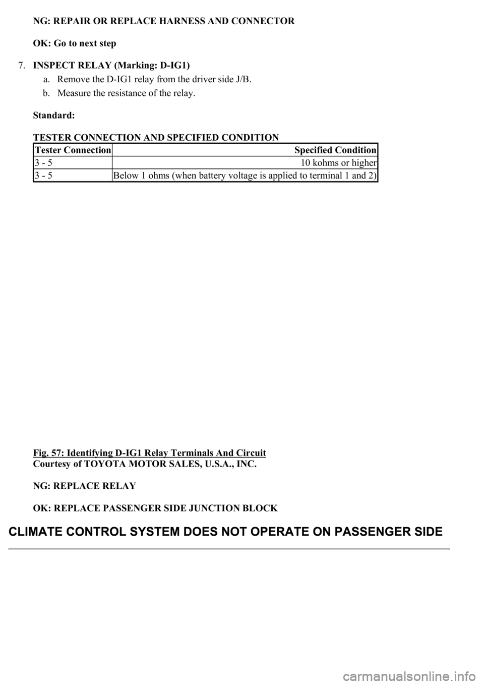
7.INSPECT RELAY (Marking: D-IG1)
a. Remove the D-IG1 relay from the driver side J/B.
b. Measure the resistance of the relay.
Standard:
TESTER CONNECTION AND SPECIFIED CONDITION
Fig. 57: Identifying D
-IG1 Relay Terminals And Circuit
Courtesy of TOYOTA MOTOR SALES, U.S.A., INC.
NG: REPLACE RELAY
OK: REPLACE PASSENGER SIDE JUNCTION BLOCK
Tester ConnectionSpecified Condition
3 - 510 kohms or higher
3 - 5Below 1 ohms (when battery voltage is applied to terminal 1 and 2)
Page 1677 of 4500
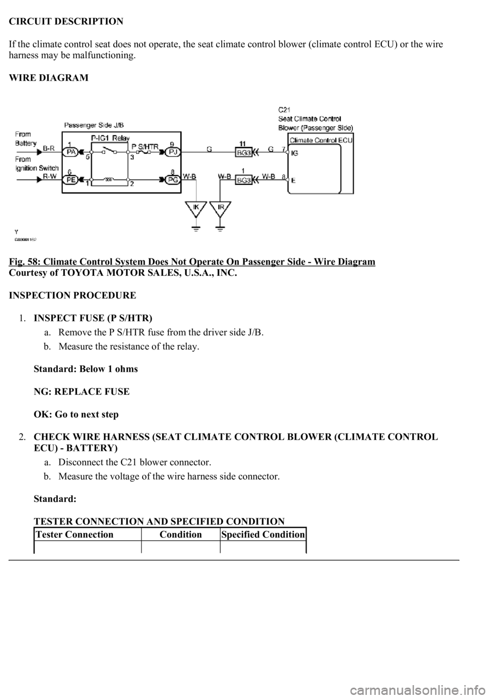
CIRCUIT DESCRIPTION
If the climate control seat does not operate, the seat climate control blower (climate control ECU) or the wire
harness may be malfunctioning.
WIRE DIAGRAM
Fig. 58: Climate Control System Does Not Operate On Passenger Side
- Wire Diagram
Courtesy of TOYOTA MOTOR SALES, U.S.A., INC.
INSPECTION PROCEDURE
1.INSPECT FUSE (P S/HTR)
a. Remove the P S/HTR fuse from the driver side J/B.
b. Measure the resistance of the relay.
Standard: Below 1 ohms
NG: REPLACE FUSE
OK: Go to next step
2.CHECK WIRE HARNESS (SEAT CLIMATE CONTROL BLOWER (CLIMATE CONTROL
ECU) - BATTERY)
a. Disconnect the C21 blower connector.
b. Measure the voltage of the wire harness side connector.
Standard:
TESTER CONNECTION AND SPECIFIED CONDITION
Tester ConnectionConditionSpecified Condition
Page 1679 of 4500
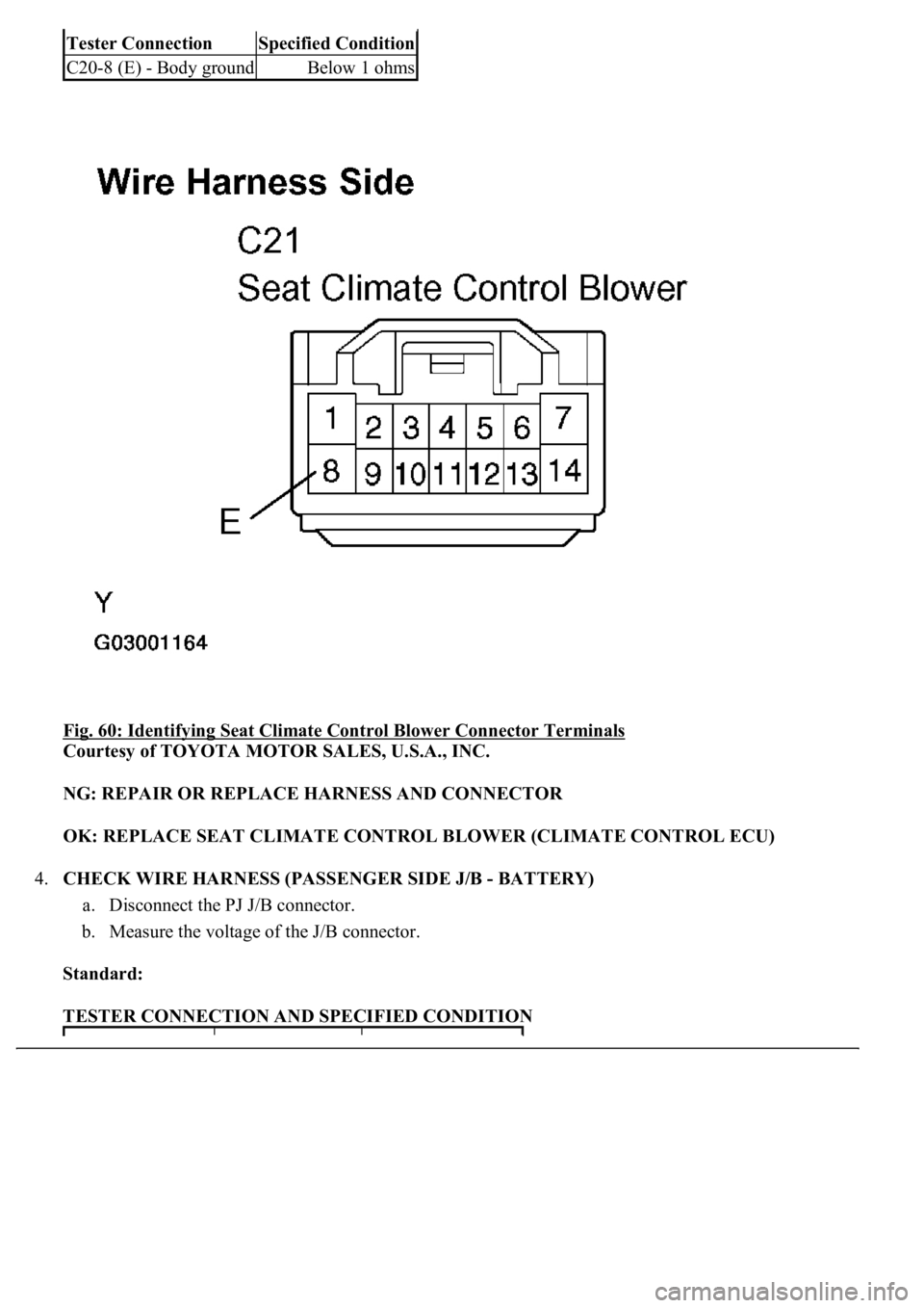
Fig. 60: Identifying Seat Climate Control Blower Connector Terminals
Courtesy of TOYOTA MOTOR SALES, U.S.A., INC.
NG: REPAIR OR REPLACE HARNESS AND CONNECTOR
OK: REPLACE SEAT CLIMATE CONTROL BLOWER (CLIMATE CONTROL ECU)
4.CHECK WIRE HARNESS (PASSENGER SIDE J/B - BATTERY)
a. Disconnect the PJ J/B connector.
b. Measure the voltage of the J/B connector.
Standard:
TESTER CONNECTION AND SPECIFIED CONDITION
Tester ConnectionSpecified Condition
C20-8 (E) - Body groundBelow 1 ohms