LEXUS LS430 2003 Factory Repair Manual
Manufacturer: LEXUS, Model Year: 2003,
Model line: LS430,
Model: LEXUS LS430 2003
Pages: 4500, PDF Size: 87.45 MB
LEXUS LS430 2003 Factory Repair Manual
LS430 2003
LEXUS
LEXUS
https://www.carmanualsonline.info/img/36/57050/w960_57050-0.png
LEXUS LS430 2003 Factory Repair Manual
Trending: content, service reset, damper, wiring diagram, service interval, Rear suspension, trip computer
Page 1751 of 4500
MULTIPLEX DTC OUTPUTS (PROCEED TO "MULTIPLEX COMMUNICATION SYSTEM")
NO MULTIPLEX DTC (GO TO STEP 5)
5.CHECK CAN COMMUNICATION SYSTEM (SEE DIAGNOSTIC TROUBLE CODE CHART
)
a. Check for DTC outputs
CAN DTC OUTPUTS (PROCEED TO "CAN COMMUNICATION SYSTEM
")
NO CAN DTC (GO TO STEP 6)
6.CIRCUIT INSPECTION (SEE ENTIRE COMBINATION METER DOES NOT OPERATE
TO
OPERATING LIGHT CONTROL RHEOSTAT DOES NOT CHANGE LIGHT BRIGHTNESS
)
7.REPAIR OR REPLACE
8.CONFIRMATION TEST
END
Page 1752 of 4500
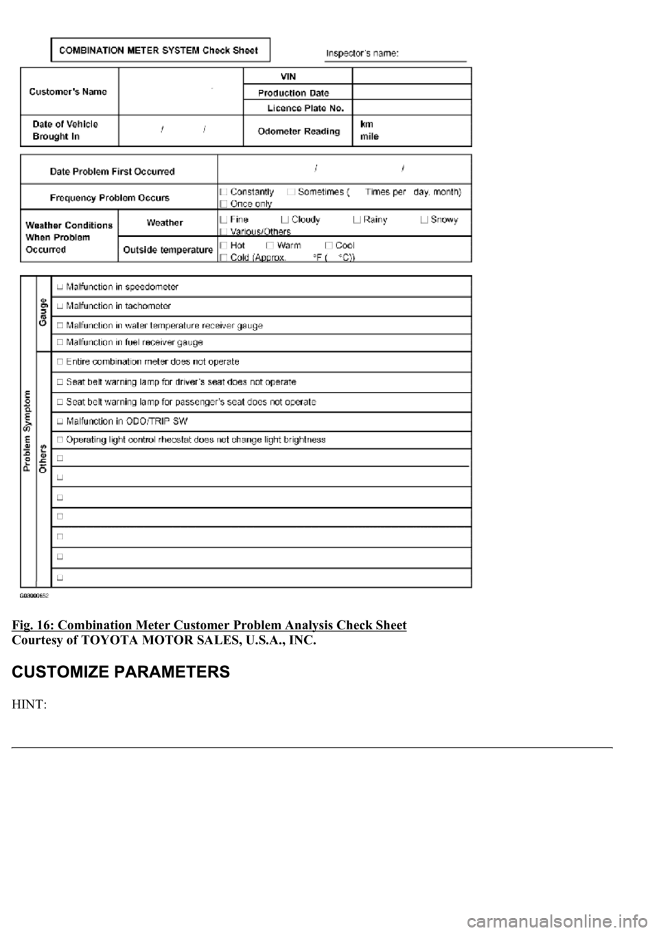
Fig. 16: Combination Meter Customer Problem Analysis Check Sheet
Courtesy of TOYOTA MOTOR SALES, U.S.A., INC.
HINT:
Page 1753 of 4500
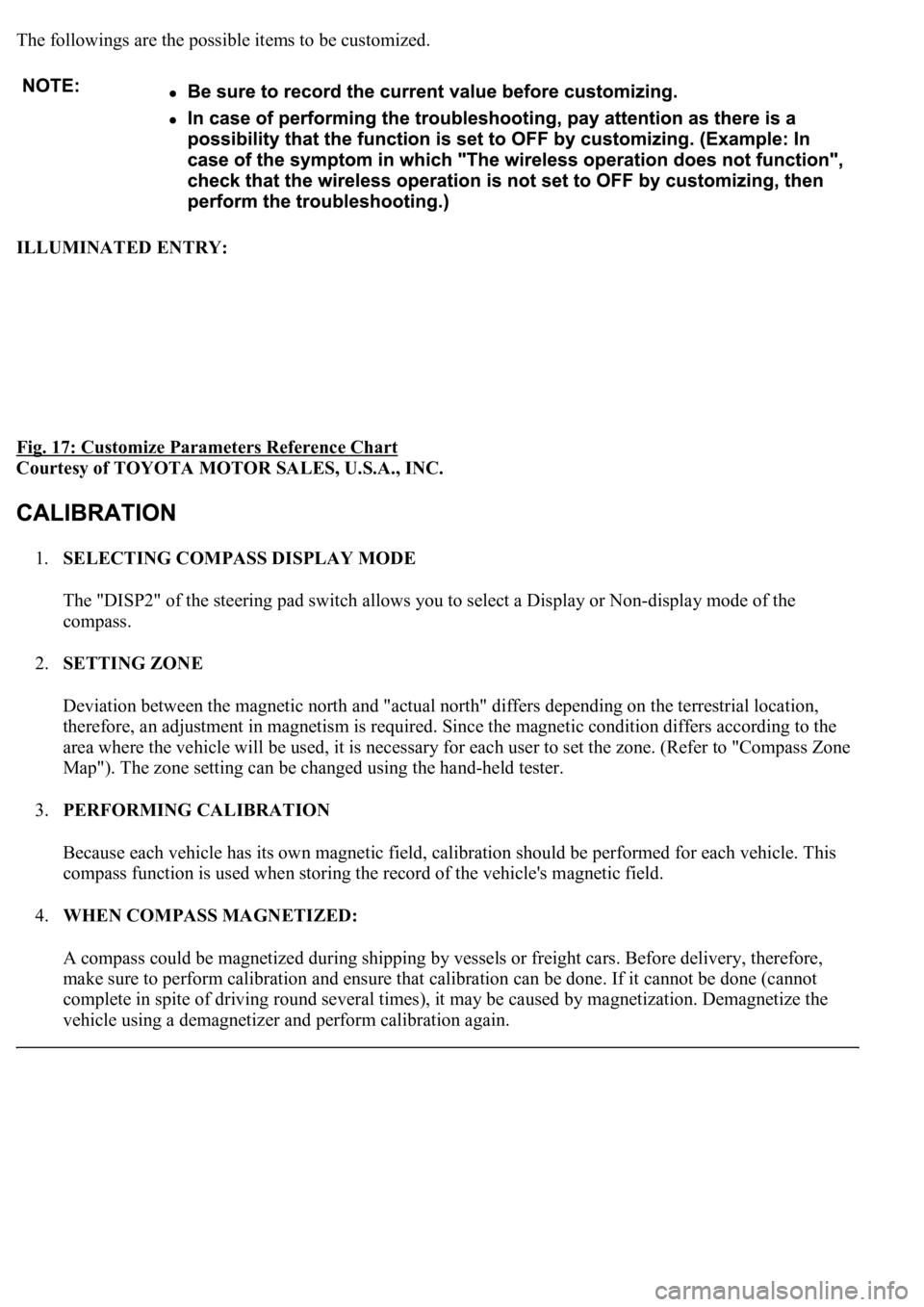
The followings are the possible items to be customized.
ILLUMINATED ENTRY:
Fig. 17: Customize Parameters Reference Chart
Courtesy of TOYOTA MOTOR SALES, U.S.A., INC.
1.SELECTING COMPASS DISPLAY MODE
The "DISP2" of the steering pad switch allows you to select a Display or Non-display mode of the
compass.
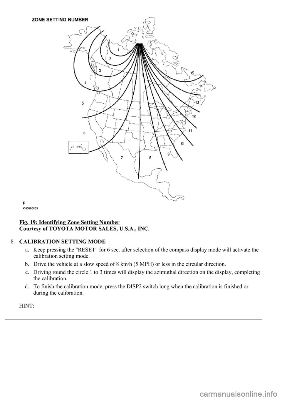
2.SETTING ZONE
Deviation between the magnetic north and "actual north" differs depending on the terrestrial location,
therefore, an adjustment in magnetism is required. Since the magnetic condition differs according to the
area where the vehicle will be used, it is necessary for each user to set the zone. (Refer to "Compass Zone
Map"). The zone setting can be changed using the hand-held tester.
3.PERFORMING CALIBRATION
Because each vehicle has its own magnetic field, calibration should be performed for each vehicle. This
compass function is used when storing the record of the vehicle's magnetic field.
4.WHEN COMPASS MAGNETIZED:
A compass could be magnetized during shipping by vessels or freight cars. Before delivery, therefore,
make sure to perform calibration and ensure that calibration can be done. If it cannot be done (cannot
complete in spite of driving round several times), it may be caused by magnetization. Demagnetize the
vehicle usin
g a demagnetizer and perform calibration again.
Page 1754 of 4500
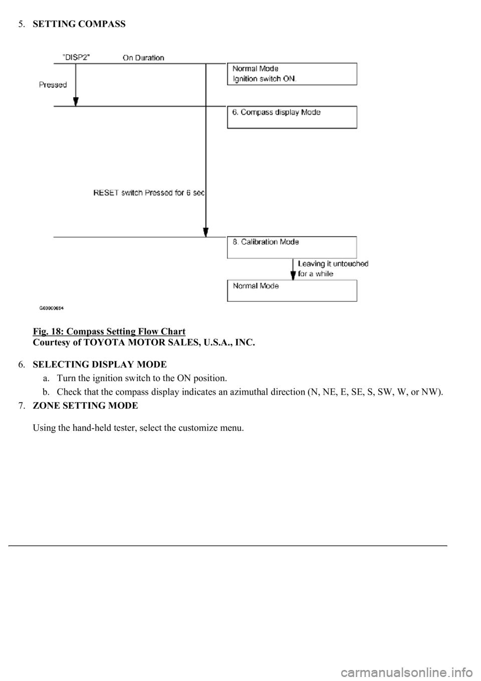
5.SETTING COMPASS
Fig. 18: Compass Setting Flow Chart
Courtesy of TOYOTA MOTOR SALES, U.S.A., INC.
6.SELECTING DISPLAY MODE
a. Turn the ignition switch to the ON position.
b. Check that the compass display indicates an azimuthal direction (N, NE, E, SE, S, SW, W, or NW).
7.ZONE SETTING MODE
Usin
g the hand-held tester, select the customize menu.
Page 1755 of 4500
Fig. 19: Identifying Zone Setting Number
Courtesy of TOYOTA MOTOR SALES, U.S.A., INC.
8.CALIBRATION SETTING MODE
a. Keep pressing the "RESET" for 6 sec. after selection of the compass display mode will activate the
calibration setting mode.
b. Drive the vehicle at a slow speed of 8 km/h (5 MPH) or less in the circular direction.
c. Driving round the circle 1 to 3 times will display the azimuthal direction on the display, completing
the calibration.
d. To finish the calibration mode, press the DISP2 switch long when the calibration is finished or
during the calibration.
HINT:
Page 1756 of 4500
Once calibration is completed, it is not necessary to perform the above procedures unless the magnetic
field strength is drastically changed.
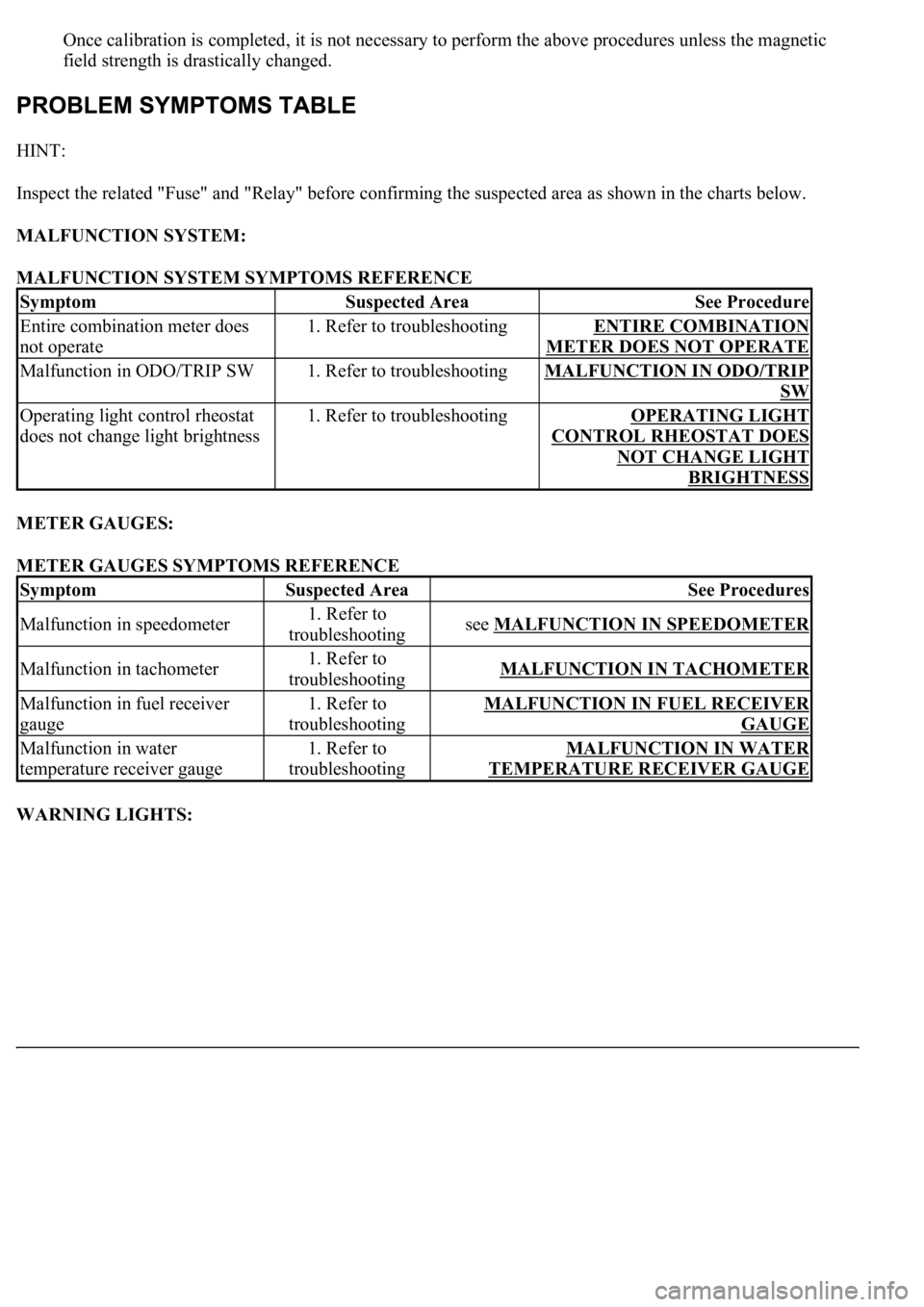
HINT:
Inspect the related "Fuse" and "Relay" before confirming the suspected area as shown in the charts below.
MALFUNCTION SYSTEM:
MALFUNCTION SYSTEM SYMPTOMS REFERENCE
METER GAUGES:
METER GAUGES SYMPTOMS REFERENCE
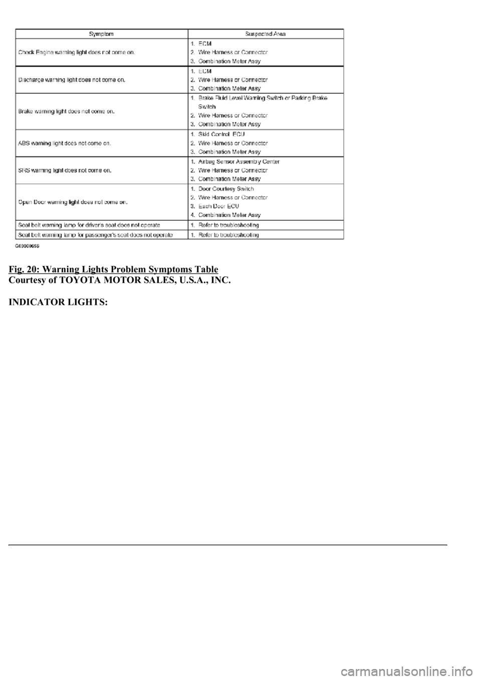
WARNING LIGHTS:
SymptomSuspected AreaSee Procedure
Entire combination meter does
not operate1. Refer to troubleshootingENTIRE COMBINATION
METER DOES NOT OPERATE
Malfunction in ODO/TRIP SW1. Refer to troubleshootingMALFUNCTION IN ODO/TRIP
SW
Operating light control rheostat
does not change light brightness1. Refer to troubleshootingOPERATING LIGHT
CONTROL RHEOSTAT DOES
NOT CHANGE LIGHT
BRIGHTNESS
SymptomSuspected AreaSee Procedures
Malfunction in speedometer1. Refer to
troubleshootingsee MALFUNCTION IN SPEEDOMETER
Malfunction in tachometer1. Refer to
troubleshootingMALFUNCTION IN TACHOMETER
Malfunction in fuel receiver
gauge1. Refer to
troubleshootingMALFUNCTION IN FUEL RECEIVER
GAUGE
Malfunction in water
temperature receiver gauge1. Refer to
troubleshootingMALFUNCTION IN WATER
TEMPERATURE RECEIVER GAUGE
Page 1757 of 4500
Fig. 20: Warning Lights Problem Symptoms Table
Courtesy of TOYOTA MOTOR SALES, U.S.A., INC.
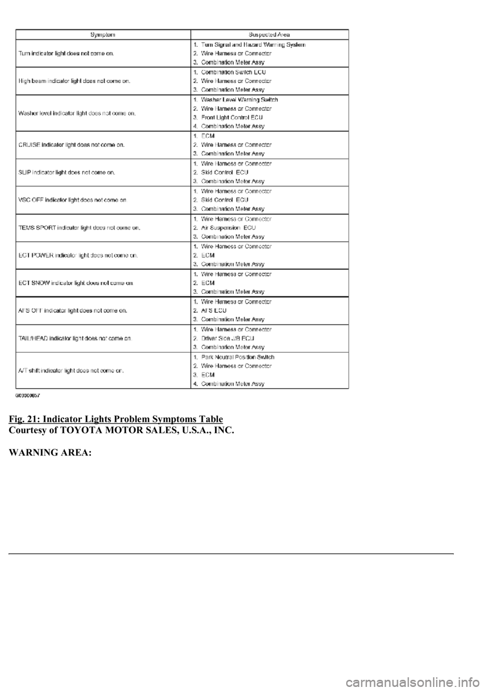
INDICATOR LIGHTS:
Page 1758 of 4500
Fig. 21: Indicator Lights Problem Symptoms Table
Courtesy of TOYOTA MOTOR SALES, U.S.A., INC.
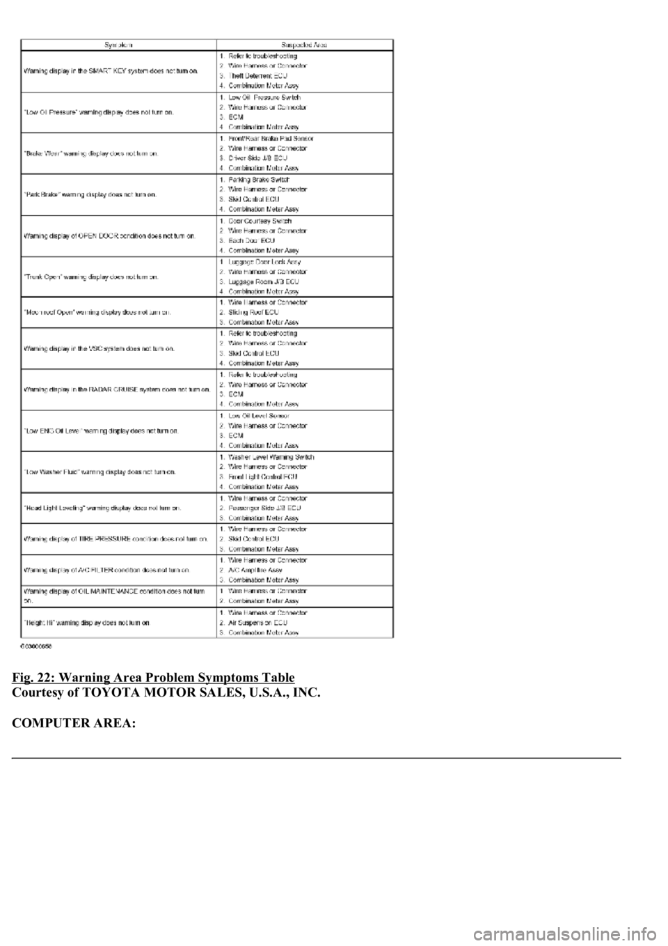
WARNING AREA:
Page 1759 of 4500
Fig. 22: Warning Area Problem Symptoms Table
Courtesy of TOYOTA MOTOR SALES, U.S.A., INC.
COMPUTER AREA:
Page 1760 of 4500
Fig. 23: Computer Area Problem Symptoms Table
Courtesy of TOYOTA MOTOR SALES, U.S.A., INC.
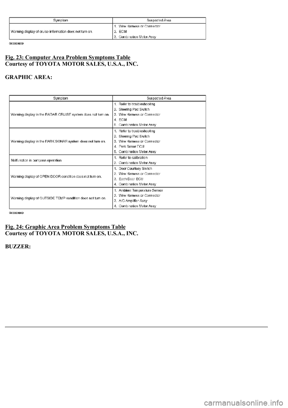
GRAPHIC AREA:
Fig. 24: Graphic Area Problem Symptoms Table
Courtesy of TOYOTA MOTOR SALES, U.S.A., INC.
BUZZER:
Trending: B2620, park, Spark plug firing order, vacuum switch, torque, low oil pressure, headlamp
