LEXUS LS430 2003 Factory Repair Manual
Manufacturer: LEXUS, Model Year: 2003,
Model line: LS430,
Model: LEXUS LS430 2003
Pages: 4500, PDF Size: 87.45 MB
LEXUS LS430 2003 Factory Repair Manual
LS430 2003
LEXUS
LEXUS
https://www.carmanualsonline.info/img/36/57050/w960_57050-0.png
LEXUS LS430 2003 Factory Repair Manual
Trending: c1725, height adjustment, replacement, coolant level, child lock, traction control, fog light
Page 1781 of 4500
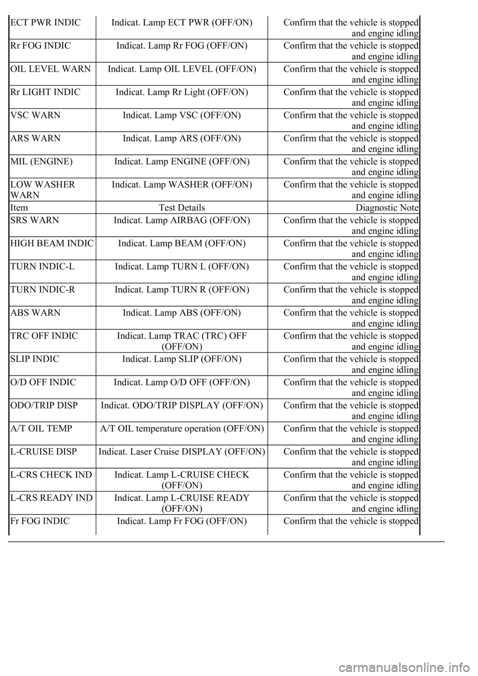
ECT PWR INDICIndicat. Lamp ECT PWR (OFF/ON)Confirm that the vehicle is stopped
and engine idling
Rr FOG INDICIndicat. Lamp Rr FOG (OFF/ON)Confirm that the vehicle is stopped
and engine idling
OIL LEVEL WARNIndicat. Lamp OIL LEVEL (OFF/ON)Confirm that the vehicle is stopped
and engine idling
Rr LIGHT INDICIndicat. Lamp Rr Light (OFF/ON)Confirm that the vehicle is stopped
and engine idling
VSC WARNIndicat. Lamp VSC (OFF/ON)Confirm that the vehicle is stopped
and engine idling
ARS WARNIndicat. Lamp ARS (OFF/ON)Confirm that the vehicle is stopped
and engine idling
MIL (ENGINE)Indicat. Lamp ENGINE (OFF/ON)Confirm that the vehicle is stopped
and engine idling
LOW WASHER
WARNIndicat. Lamp WASHER (OFF/ON)Confirm that the vehicle is stopped
and engine idling
ItemTest DetailsDiagnostic Note
SRS WARNIndicat. Lamp AIRBAG (OFF/ON)Confirm that the vehicle is stopped
and engine idling
HIGH BEAM INDICIndicat. Lamp BEAM (OFF/ON)Confirm that the vehicle is stopped
and engine idling
TURN INDIC-LIndicat. Lamp TURN L (OFF/ON)Confirm that the vehicle is stopped
and engine idling
TURN INDIC-RIndicat. Lamp TURN R (OFF/ON)Confirm that the vehicle is stopped
and engine idling
ABS WARNIndicat. Lamp ABS (OFF/ON)Confirm that the vehicle is stopped
and engine idling
TRC OFF INDICIndicat. Lamp TRAC (TRC) OFF
(OFF/ON)Confirm that the vehicle is stopped
and engine idling
SLIP INDICIndicat. Lamp SLIP (OFF/ON)Confirm that the vehicle is stopped
and engine idling
O/D OFF INDICIndicat. Lamp O/D OFF (OFF/ON)Confirm that the vehicle is stopped
and engine idling
ODO/TRIP DISPIndicat. ODO/TRIP DISPLAY (OFF/ON)Confirm that the vehicle is stopped
and engine idling
A/T OIL TEMPA/T OIL temperature operation (OFF/ON)Confirm that the vehicle is stopped
and engine idling
L-CRUISE DISPIndicat. Laser Cruise DISPLAY (OFF/ON)Confirm that the vehicle is stopped
and engine idling
L-CRS CHECK INDIndicat. Lamp L-CRUISE CHECK
(OFF/ON)Confirm that the vehicle is stopped
and engine idling
L-CRS READY INDIndicat. Lamp L-CRUISE READY
(OFF/ON)Confirm that the vehicle is stopped
and engine idling
Fr FOG INDICIndicat. Lamp Fr FOG (OFF/ON)Confirm that the vehicle is stopped
Page 1782 of 4500
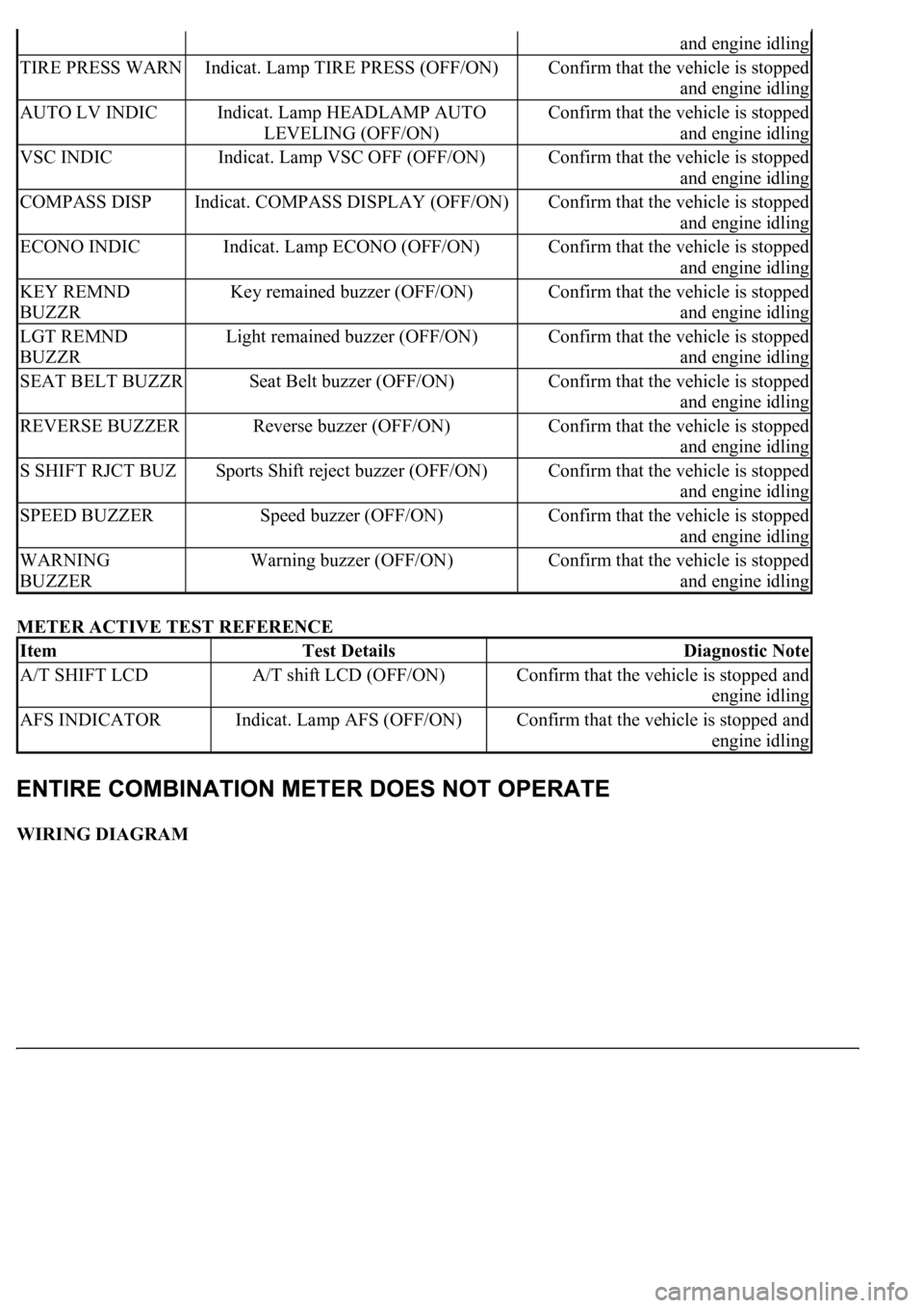
METER ACTIVE TEST REFERENCE
WIRING DIAGRAM
and engine idling
TIRE PRESS WARNIndicat. Lamp TIRE PRESS (OFF/ON)Confirm that the vehicle is stopped
and engine idling
AUTO LV INDICIndicat. Lamp HEADLAMP AUTO
LEVELING (OFF/ON)Confirm that the vehicle is stopped
and engine idling
VSC INDICIndicat. Lamp VSC OFF (OFF/ON)Confirm that the vehicle is stopped
and engine idling
COMPASS DISPIndicat. COMPASS DISPLAY (OFF/ON)Confirm that the vehicle is stopped
and engine idling
ECONO INDICIndicat. Lamp ECONO (OFF/ON)Confirm that the vehicle is stopped
and engine idling
KEY REMND
BUZZRKey remained buzzer (OFF/ON)Confirm that the vehicle is stopped
and engine idling
LGT REMND
BUZZRLight remained buzzer (OFF/ON)Confirm that the vehicle is stopped
and engine idling
SEAT BELT BUZZRSeat Belt buzzer (OFF/ON)Confirm that the vehicle is stopped
and engine idling
REVERSE BUZZERReverse buzzer (OFF/ON)Confirm that the vehicle is stopped
and engine idling
S SHIFT RJCT BUZSports Shift reject buzzer (OFF/ON)Confirm that the vehicle is stopped
and engine idling
SPEED BUZZERSpeed buzzer (OFF/ON)Confirm that the vehicle is stopped
and engine idling
WARNING
BUZZERWarning buzzer (OFF/ON)Confirm that the vehicle is stopped
and engine idling
ItemTest DetailsDiagnostic Note
A/T SHIFT LCDA/T shift LCD (OFF/ON)Confirm that the vehicle is stopped and
engine idling
AFS INDICATORIndicat. Lamp AFS (OFF/ON)Confirm that the vehicle is stopped and
engine idling
Page 1783 of 4500
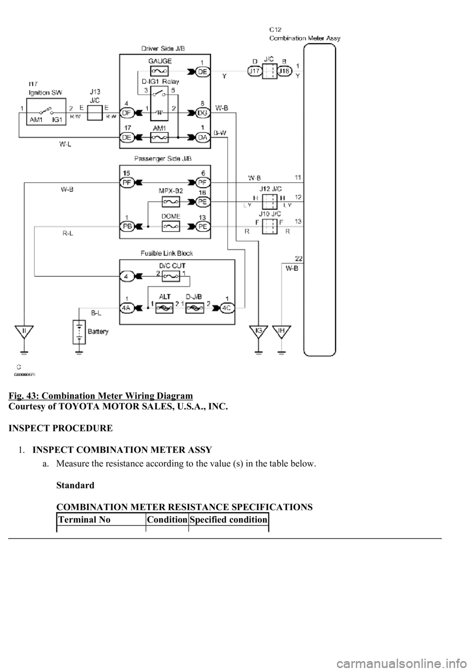
Fig. 43: Combination Meter Wiring Diagram
Courtesy of TOYOTA MOTOR SALES, U.S.A., INC.
INSPECT PROCEDURE
1.INSPECT COMBINATION METER ASSY
a. Measure the resistance according to the value (s) in the table below.
Standard
COMBINATION METER RESISTANCE SPECIFICATIONS
Terminal NoConditionSpecified condition
Page 1784 of 4500
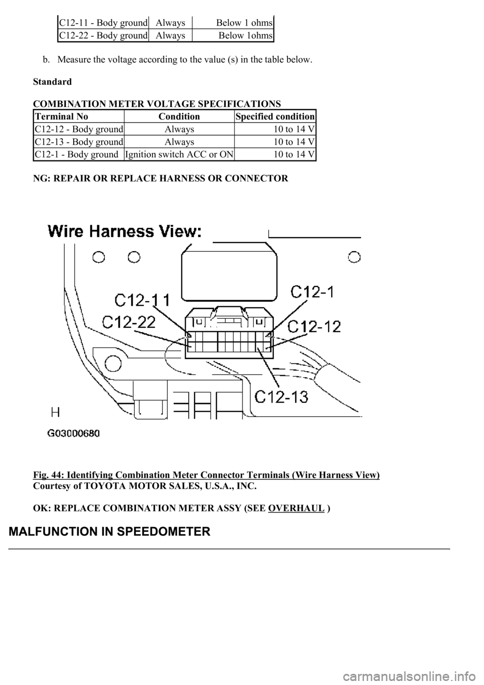
b. Measure the voltage according to the value (s) in the table below.
Standard
COMBINATION METER VOLTAGE SPECIFICATIONS
NG: REPAIR OR REPLACE HARNESS OR CONNECTOR
Fig. 44: Identifying Combination Meter Connector Terminals (Wire Harness View)
Courtesy of TOYOTA MOTOR SALES, U.S.A., INC.
OK: REPLACE COMBINATION METER ASSY (SEE OVERHAUL
)
C12-11 - Body groundAlwaysBelow 1 ohms
C12-22 - Body groundAlwaysBelow 1ohms
Terminal NoConditionSpecified condition
C12-12 - Body groundAlways10 to 14 V
C12-13 - Body groundAlways10 to 14 V
C12-1 - Body groundIgnition switch ACC or ON10 to 14 V
Page 1785 of 4500
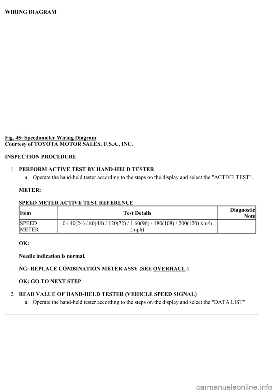
WIRING DIAGRAM
Fig. 45: Speedometer Wiring Diagram
Courtesy of TOYOTA MOTOR SALES, U.S.A., INC.
INSPECTION PROCEDURE
1.PERFORM ACTIVE TEST BY HAND-HELD TESTER
a. Operate the hand-held tester according to the steps on the display and select the "ACTIVE TEST".
METER:
SPEED METER ACTIVE TEST REFERENCE
OK:
Needle indication is normal.
NG: REPLACE COMBINATION METER ASSY (SEE OVERHAUL
)
OK: GO TO NEXT STEP
2.READ VALUE OF HAND-HELD TESTER (VEHICLE SPEED SIGNAL)
a. Operate the han
d-held tester according to the steps on the display and select the "DATA LIST"
ItemTest DetailsDiagnostic
Note
SPEED
METER0 / 40(24) / 80(48) / 120(72) / 1 60(96) / 180(108) / 200(120) km/h
(mph)-
Page 1786 of 4500
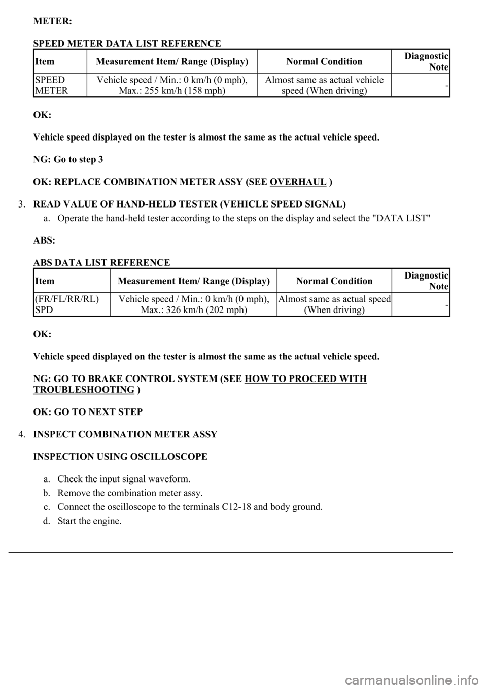
METER:
SPEED METER DATA LIST REFERENCE
OK:
Vehicle speed displayed on the tester is almost the same as the actual vehicle speed.
NG: Go to step 3
OK: REPLACE COMBINATION METER ASSY (SEE OVERHAUL
)
3.READ VALUE OF HAND-HELD TESTER (VEHICLE SPEED SIGNAL)
a. Operate the hand-held tester according to the steps on the display and select the "DATA LIST"
ABS:
ABS DATA LIST REFERENCE
OK:
Vehicle speed displayed on the tester is almost the same as the actual vehicle speed.
NG: GO TO BRAKE CONTROL SYSTEM (SEE HOW TO PROCEED WITH
TROUBLESHOOTING )
OK: GO TO NEXT STEP
4.INSPECT COMBINATION METER ASSY
INSPECTION USING OSCILLOSCOPE
a. Check the input signal waveform.
b. Remove the combination meter assy.
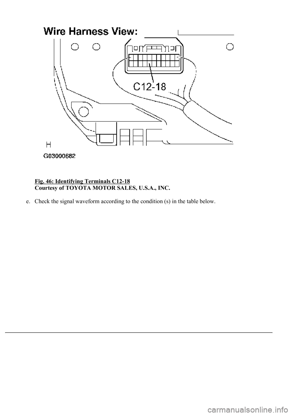
c. Connect the oscilloscope to the terminals C12-18 and body ground.
d. Start the en
gine.
ItemMeasurement Item/ Range (Display)Normal ConditionDiagnostic
Note
SPEED
METERVehicle speed / Min.: 0 km/h (0 mph),
Max.: 255 km/h (158 mph)Almost same as actual vehicle
speed (When driving)-
ItemMeasurement Item/ Range (Display)Normal ConditionDiagnostic
Note
(FR/FL/RR/RL)
SPDVehicle speed / Min.: 0 km/h (0 mph),
Max.: 326 km/h (202 mph)Almost same as actual speed
(When driving)-
Page 1787 of 4500
Fig. 46: Identifying Terminals C12-18
Courtesy of TOYOTA MOTOR SALES, U.S.A., INC.
e. Check the si
gnal waveform according to the condition (s) in the table below.
Page 1788 of 4500
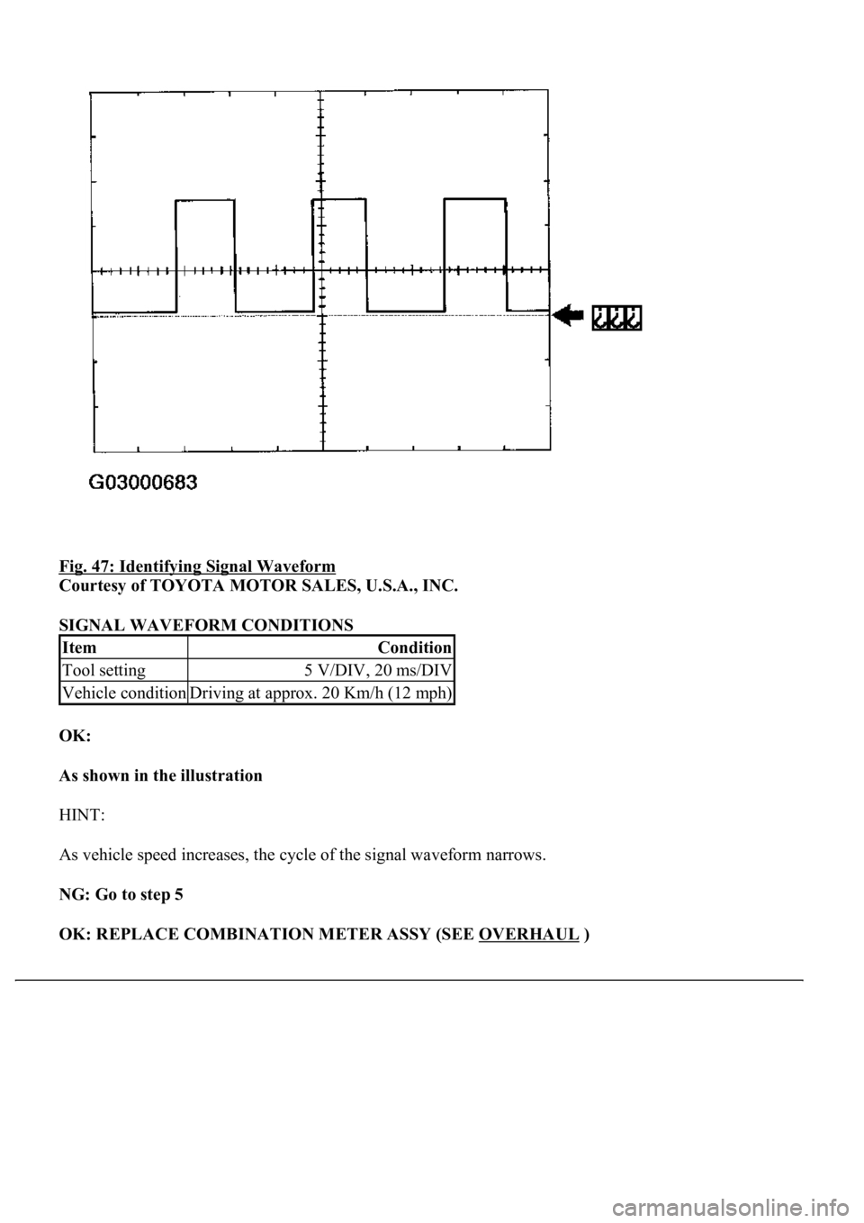
Fig. 47: Identifying Signal Waveform
Courtesy of TOYOTA MOTOR SALES, U.S.A., INC.
SIGNAL WAVEFORM CONDITIONS
OK:
As shown in the illustration
HINT:
As vehicle speed increases, the cycle of the signal waveform narrows.
NG: Go to step 5
OK: REPLACE COMBINATION METER ASSY (SEE OVERHAUL
)
ItemCondition
Tool setting5 V/DIV, 20 ms/DIV
Vehicle conditionDriving at approx. 20 Km/h (12 mph)
Page 1789 of 4500
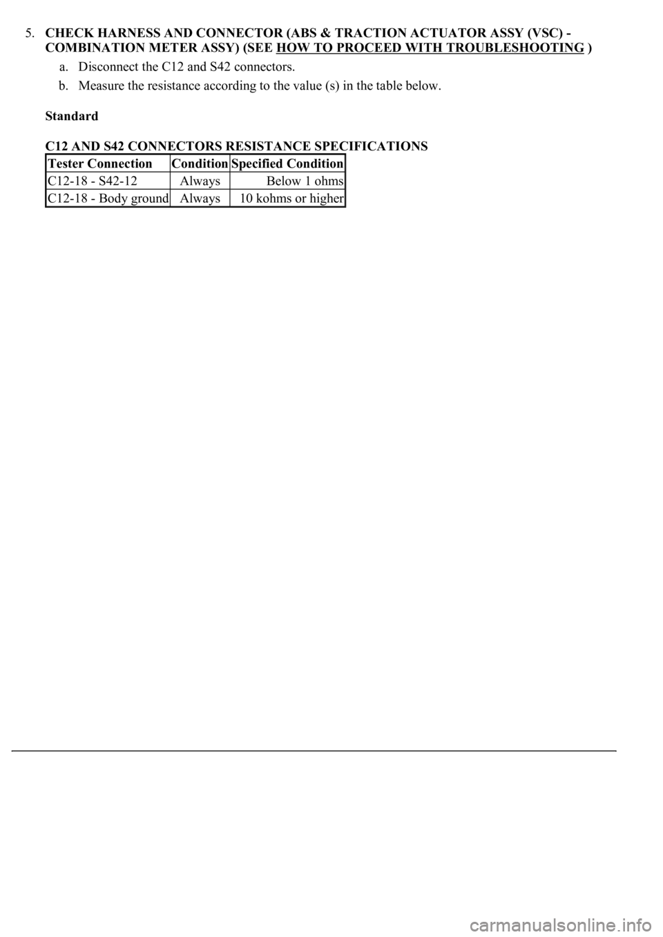
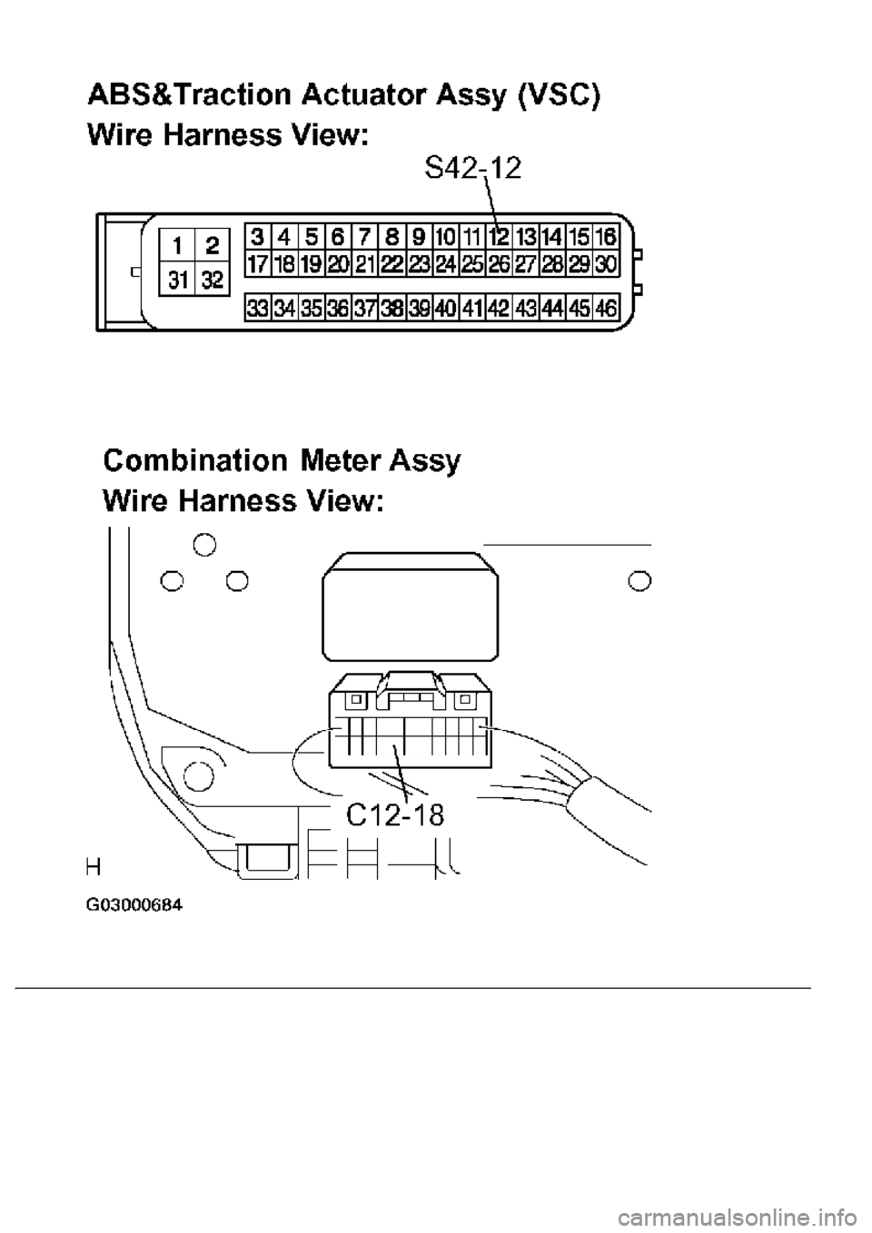
5.CHECK HARNESS AND CONNECTOR (ABS & TRACTION ACTUATOR ASSY (VSC) -
COMBINATION METER ASSY) (SEE HOW TO PROCEED WITH TROUBLESHOOTING
)
a. Disconnect the C12 and S42 connectors.
b. Measure the resistance according to the value (s) in the table below.
Standard
C12 AND S42 CONNECTORS RESISTANCE SPECIFICATIONS
Tester ConnectionConditionSpecified Condition
C12-18 - S42-12AlwaysBelow 1 ohms
C12-18 - Body groundAlways10 kohms or higher
Page 1790 of 4500
Trending: horn, oil type, engine coolant, service, brakes, check engine light, B1278


