LEXUS LS430 2003 Factory Repair Manual
Manufacturer: LEXUS, Model Year: 2003,
Model line: LS430,
Model: LEXUS LS430 2003
Pages: 4500, PDF Size: 87.45 MB
LEXUS LS430 2003 Factory Repair Manual
LS430 2003
LEXUS
LEXUS
https://www.carmanualsonline.info/img/36/57050/w960_57050-0.png
LEXUS LS430 2003 Factory Repair Manual
Trending: fuel type, wheel bolt torque, brake light, brake sensor, brake pads, oil change, traction control
Page 1951 of 4500
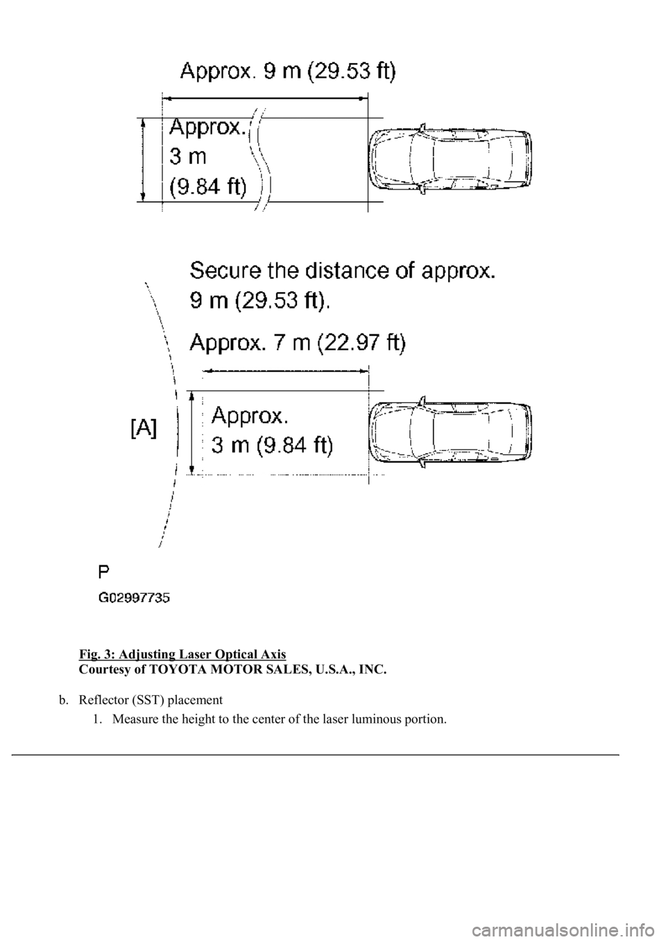
Fig. 3: Adjusting Laser Optical Axis
Courtesy of TOYOTA MOTOR SALES, U.S.A., INC.
b. Reflector (SST) placement
1. Measure the hei
ght to the center of the laser luminous portion.
Page 1952 of 4500
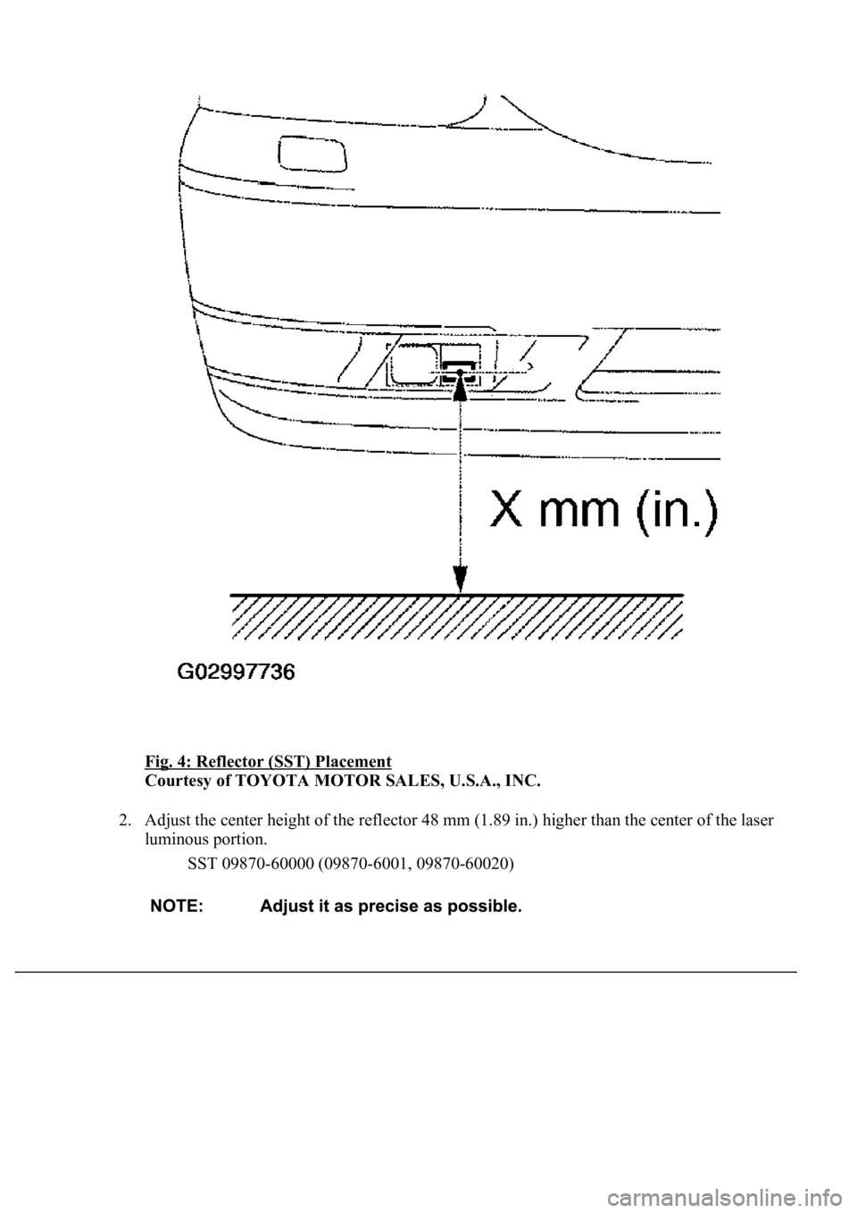
Fig. 4: Reflector (SST) Placement
Courtesy of TOYOTA MOTOR SALES, U.S.A., INC.
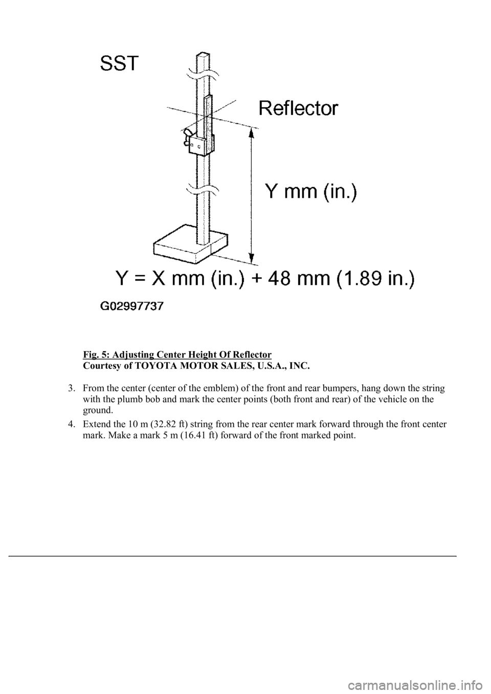
2. Adjust the center height of the reflector 48 mm (1.89 in.) higher than the center of the laser
luminous portion.
SST 09870-60000 (09870-6001, 09870-60020)
Page 1953 of 4500
Fig. 5: Adjusting Center Height Of Reflector
Courtesy of TOYOTA MOTOR SALES, U.S.A., INC.
3. From the center (center of the emblem) of the front and rear bumpers, hang down the string
with the plumb bob and mark the center points (both front and rear) of the vehicle on the
ground.
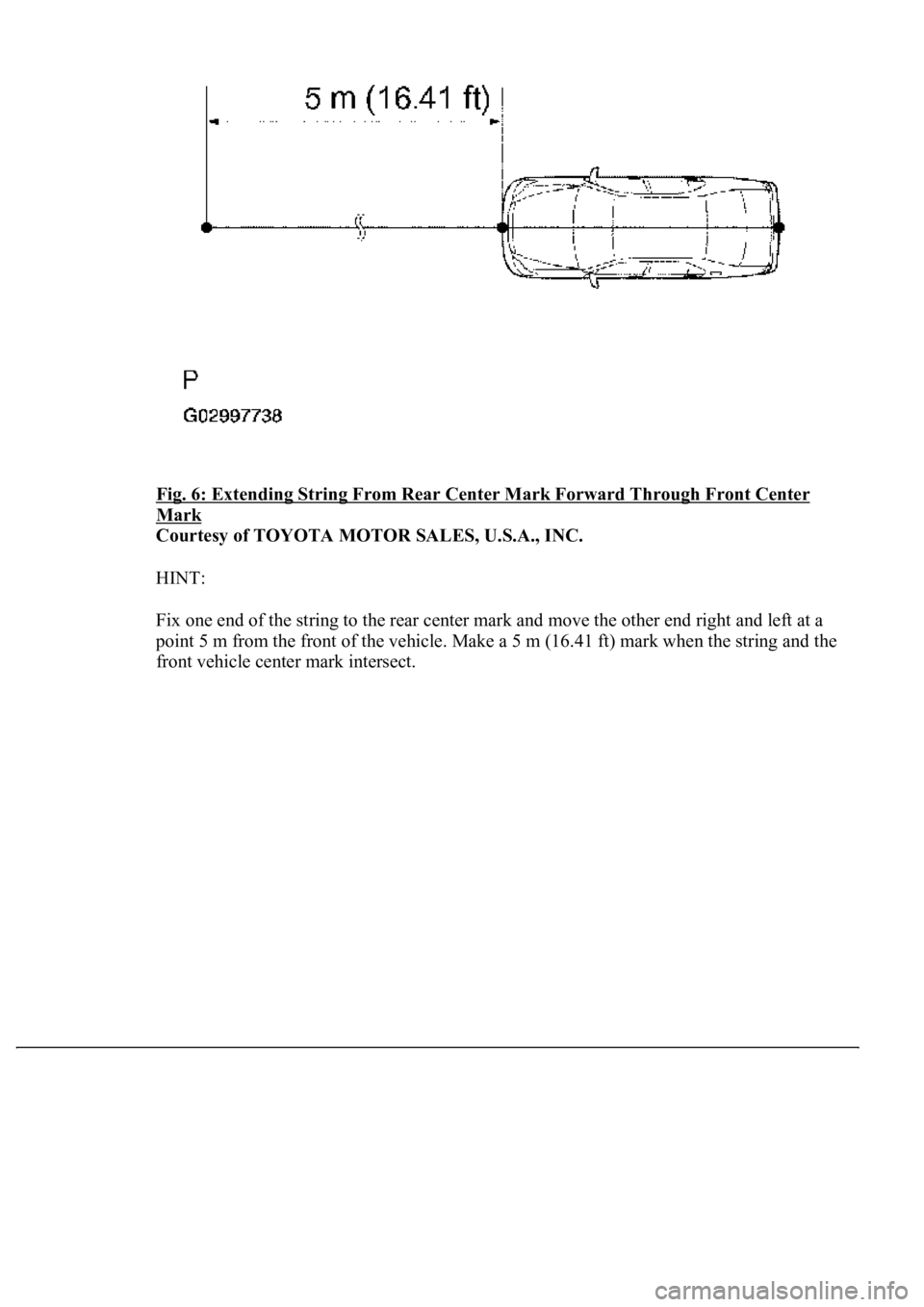
4. Extend the 10 m (32.82 ft) string from the rear center mark forward through the front center
mark. Make a mark 5 m (16.41 ft) forward of the front marked point.
Page 1954 of 4500
Fig. 6: Extending String From Rear Center Mark Forward Through Front Center
Mark
Courtesy of TOYOTA MOTOR SALES, U.S.A., INC.
HINT:
Fix one end of the string to the rear center mark and move the other end right and left at a
point 5 m from the front of the vehicle. Make a 5 m (16.41 ft) mark when the string and the
front vehicle center mark intersect.
Page 1955 of 4500
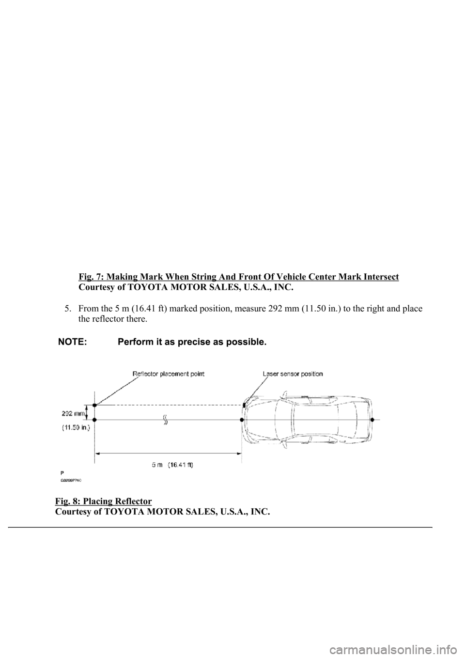
Fig. 7: Making Mark When String And Front Of Vehicle Center Mark Intersect
Courtesy of TOYOTA MOTOR SALES, U.S.A., INC.
5. From the 5 m (16.41 ft) marked position, measure 292 mm (11.50 in.) to the right and place
the reflector there.
Fig. 8: Placing Reflector
Courtesy of TOYOTA MOTOR SALES, U.S.A., INC.
Page 1956 of 4500
c. Adjust the laser beam axis
1. Turn the ignition switch to the ON position.
2. Push the cruise control main switch ON-OFF button on.
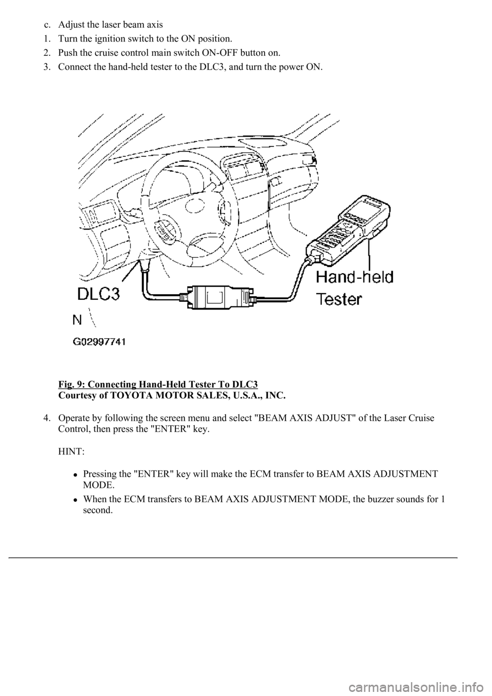
3. Connect the hand-held tester to the DLC3, and turn the power ON.
Fig. 9: Connecting Hand
-Held Tester To DLC3
Courtesy of TOYOTA MOTOR SALES, U.S.A., INC.
4. Operate by following the screen menu and select "BEAM AXIS ADJUST" of the Laser Cruise
Control, then press the "ENTER" key.
HINT:
Pressing the "ENTER" key will make the ECM transfer to BEAM AXIS ADJUSTMENT
MODE.
When the ECM transfers to BEAM AXIS ADJUSTMENT MODE, the buzzer sounds for 1
second.
Page 1957 of 4500
Fig. 10: Selecting "BEAM AXIS ADJUST" Screen
Courtesy of TOYOTA MOTOR SALES, U.S.A., INC.
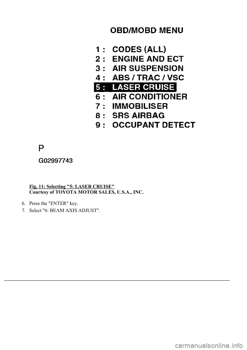
5. Select "5: LASER CRUISE".
Page 1958 of 4500
Fig. 11: Selecting "5: LASER CRUISE"
Courtesy of TOYOTA MOTOR SALES, U.S.A., INC.
6. Press the "ENTER" key.
7. Select "6: BEAM AXIS ADJUST".
Page 1959 of 4500
Fig. 12: Selecting "6: BEAM AXIS ADJUST"
Courtesy of TOYOTA MOTOR SALES, U.S.A., INC.
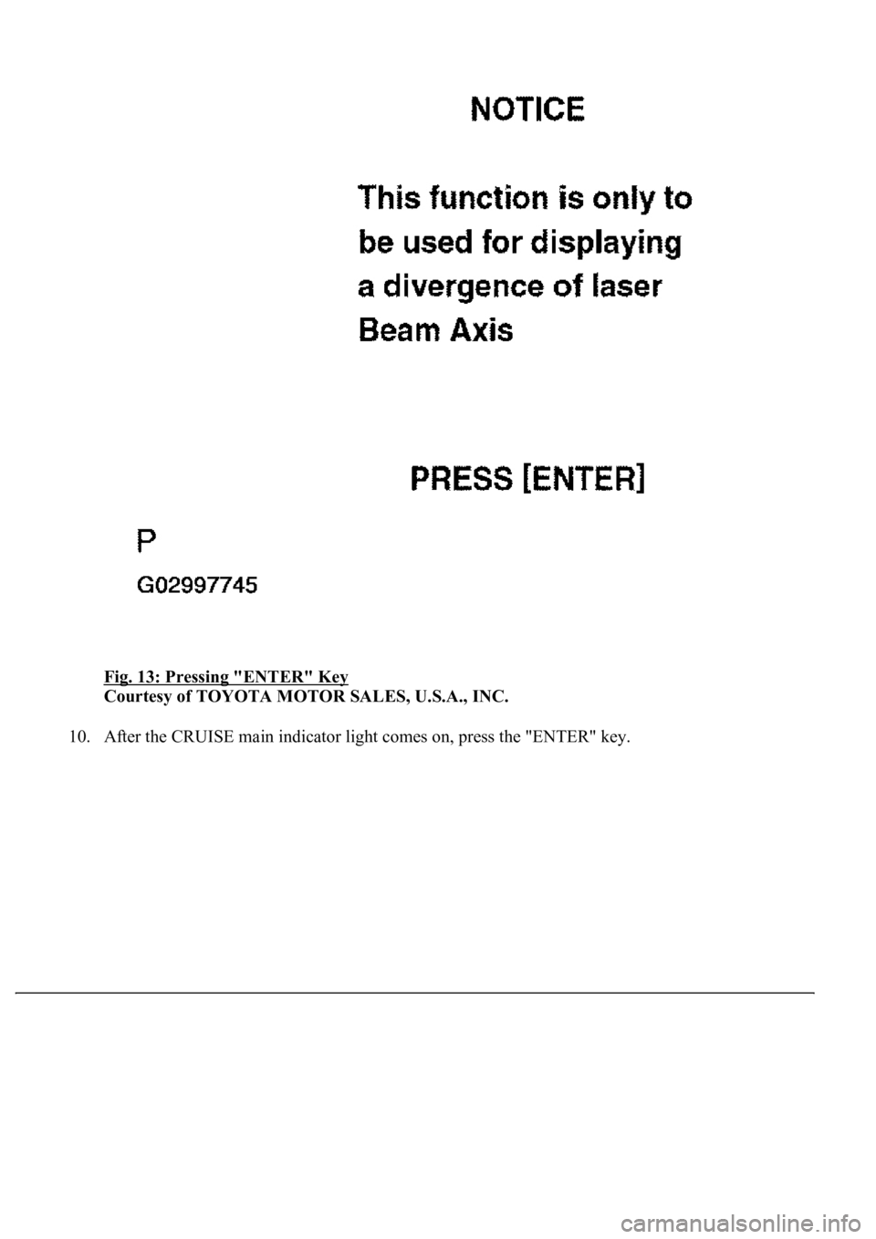
8. Press the "ENTER" key.
9. Press the "ENTER" ke
y.
Page 1960 of 4500
Fig. 13: Pressing "ENTER" Key
Courtesy of TOYOTA MOTOR SALES, U.S.A., INC.
10. After the CRUISE main indicator li
ght comes on, press the "ENTER" key.
Trending: AUX, fuel pressure, navigation system, length, coolant capacity, brake pads, fuel system
