LEXUS LS430 2003 Factory Repair Manual
Manufacturer: LEXUS, Model Year: 2003,
Model line: LS430,
Model: LEXUS LS430 2003
Pages: 4500, PDF Size: 87.45 MB
LEXUS LS430 2003 Factory Repair Manual
LS430 2003
LEXUS
LEXUS
https://www.carmanualsonline.info/img/36/57050/w960_57050-0.png
LEXUS LS430 2003 Factory Repair Manual
Trending: spare tire, oil level, recommended oil, glove box, lumbar support, inter lock cable, fuse chart
Page 1981 of 4500
display on the combination meter when starting the beam axis adjustment mode with the hand-held
tester.
Fig. 35: Confirming Current Distance
Courtesy of TOYOTA MOTOR SALES, U.S.A., INC.
g. Adjustment in horizontal direction
1. Read the divergence in the current angle.
Standard:
0° (Both right and left)
2. Based on the measured divergence of the beam axis, turn and adjust screw B for horizontal
adjustment of the millimeter wave radar sensor using a hexagon wrench.
HINT:
Page 1982 of 4500
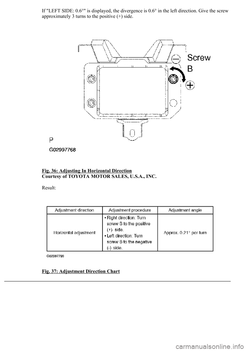
If "LEFT SIDE: 0.6°" is displayed, the divergence is 0.6° in the left direction. Give the screw
approximately 3 turns to the positive (+) side.
Fig. 36: Adjusting In Horizontal Direction
Courtesy of TOYOTA MOTOR SALES, U.S.A., INC.
Result:
Fig. 37: Adjustment Direction Chart
Page 1983 of 4500
Courtesy of TOYOTA MOTOR SALES, U.S.A., INC.
HINT:
If the value does not change to 0°, it is possible that the sensor is aiming at something
different. Reconfirm that there are no reflective materials in the surroundings.
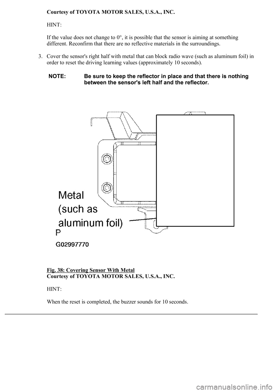
3. Cover the sensor's right half with metal that can block radio wave (such as aluminum foil) in
order to reset the driving learning values (approximately 10 seconds).
Fig. 38: Covering Sensor With Metal
Courtesy of TOYOTA MOTOR SALES, U.S.A., INC.
HINT:
When the reset is completed, the buzzer sounds for 10 seconds.
Page 1984 of 4500
4. Disconnect the hand-held tester from the DLC3.
h. Recheck vertical adjustment of the millimeter wave radar sensor.
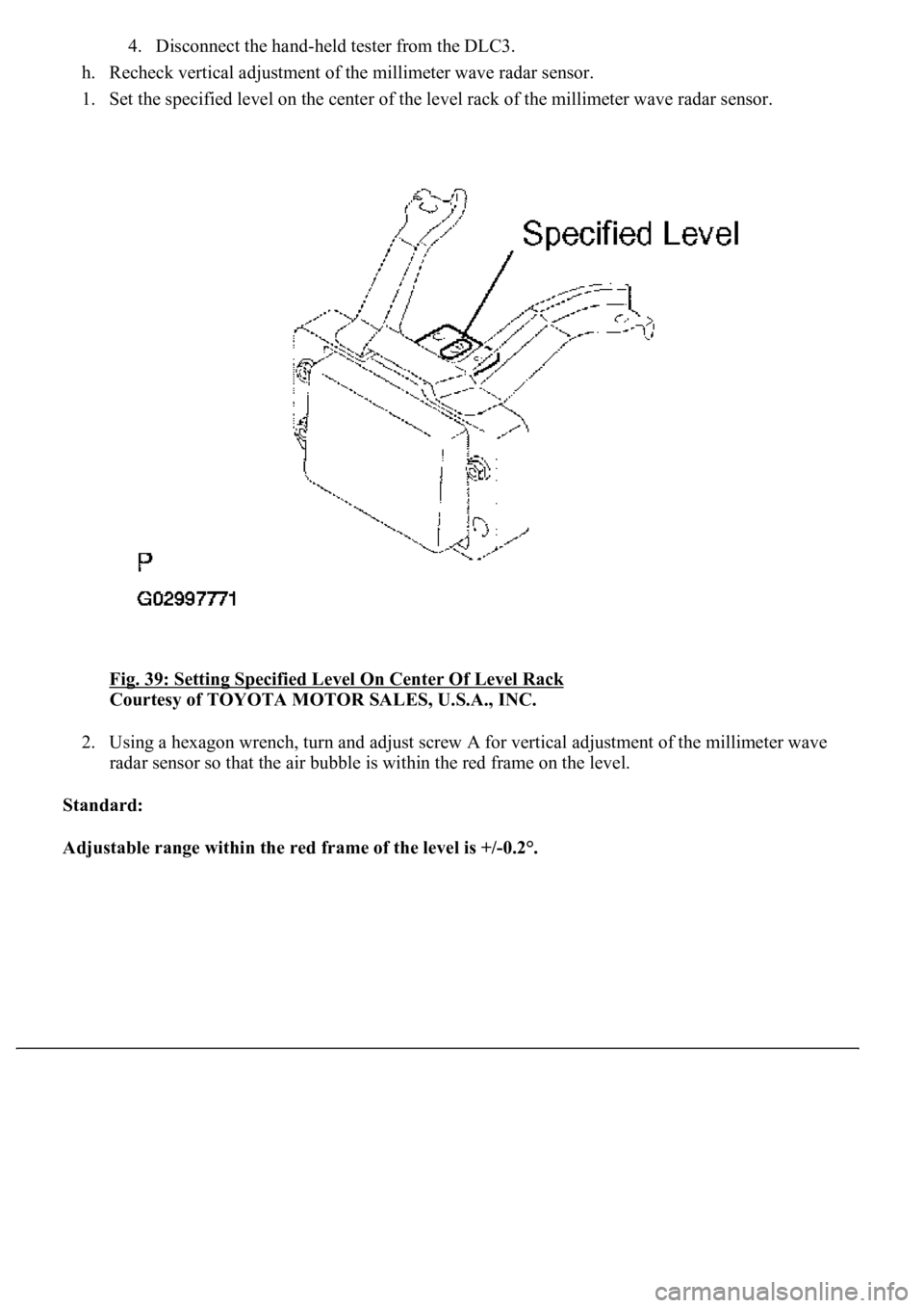
1. Set the specified level on the center of the level rack of the millimeter wave radar sensor.
Fig. 39: Setting Specified Level On Center Of Level Rack
Courtesy of TOYOTA MOTOR SALES, U.S.A., INC.
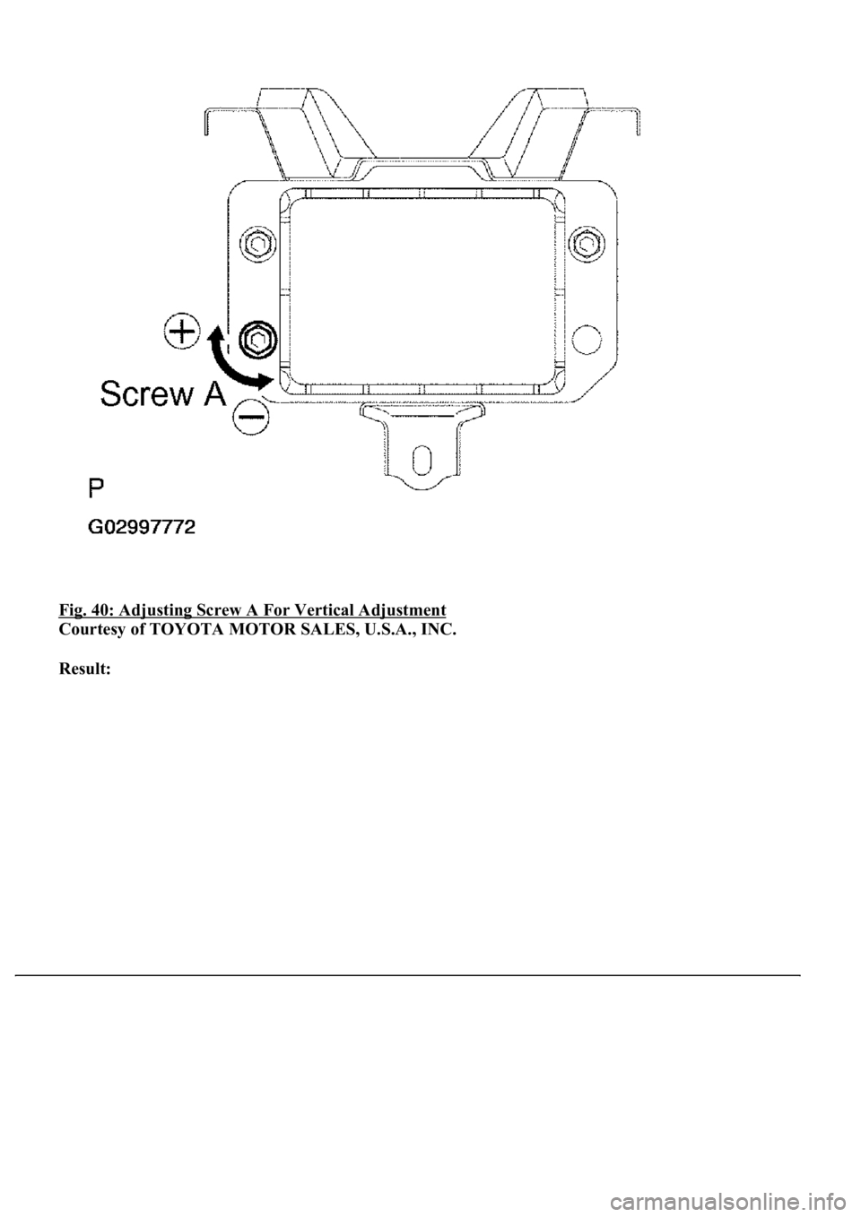
2. Using a hexagon wrench, turn and adjust screw A for vertical adjustment of the millimeter wave
radar sensor so that the air bubble is within the red frame on the level.
Standard:
Adjustable range within the red frame of the level is +/-0.2°.
Page 1985 of 4500
Fig. 40: Adjusting Screw A For Vertical Adjustment
Courtesy of TOYOTA MOTOR SALES, U.S.A., INC.
Result:
Page 1986 of 4500
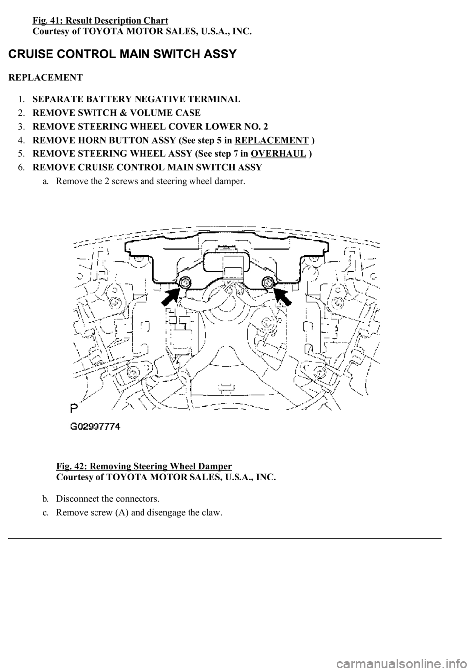
Fig. 41: Result Description Chart
Courtesy of TOYOTA MOTOR SALES, U.S.A., INC.
REPLACEMENT
1.SEPARATE BATTERY NEGATIVE TERMINAL
2.REMOVE SWITCH & VOLUME CASE
3.REMOVE STEERING WHEEL COVER LOWER NO. 2
4.REMOVE HORN BUTTON ASSY (See step 5 in REPLACEMENT
)
5.REMOVE STEERING WHEEL ASSY (See step 7 in OVERHAUL
)
6.REMOVE CRUISE CONTROL MAIN SWITCH ASSY
a. Remove the 2 screws and steering wheel damper.
Fig. 42: Removing Steering Wheel Damper
Courtesy of TOYOTA MOTOR SALES, U.S.A., INC.
b. Disconnect the connectors.
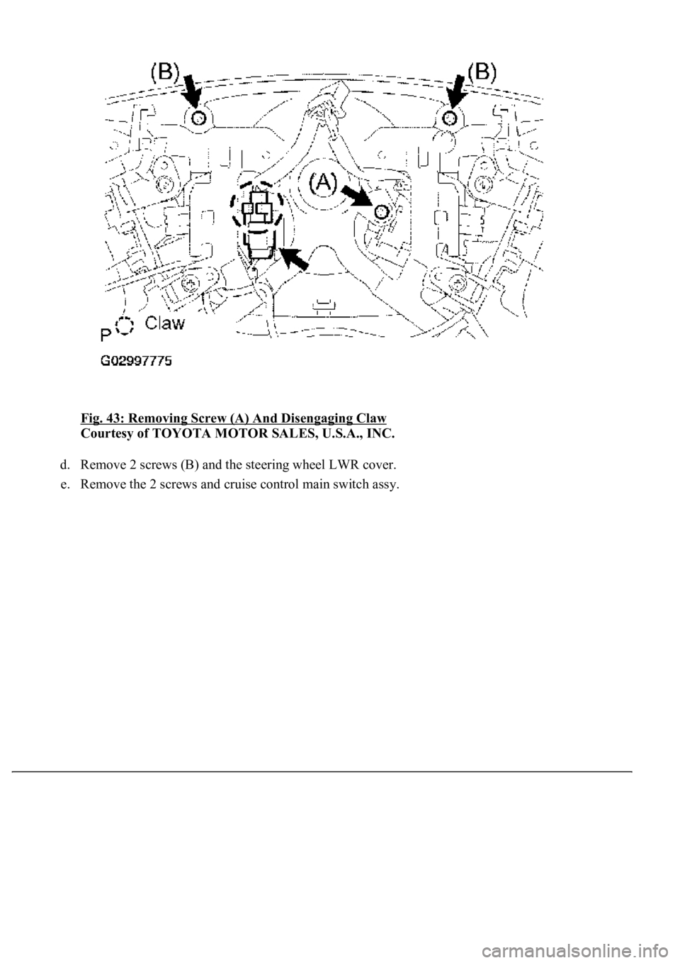
c. Remove screw (A) and disengage the claw.
Page 1987 of 4500
Fig. 43: Removing Screw (A) And Disengaging Claw
Courtesy of TOYOTA MOTOR SALES, U.S.A., INC.
d. Remove 2 screws (B) and the steering wheel LWR cover.
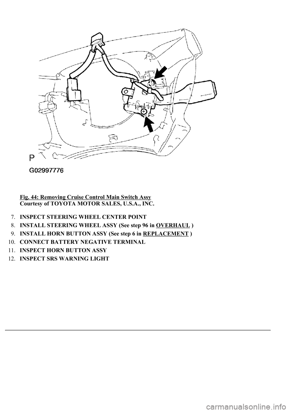
e. Remove the 2 screws and cruise control main switch ass
y.
Page 1988 of 4500
Fig. 44: Removing Cruise Control Main Switch Assy
Courtesy of TOYOTA MOTOR SALES, U.S.A., INC.
7.INSPECT STEERING WHEEL CENTER POINT
8.INSTALL STEERING WHEEL ASSY (See step 96 in OVERHAUL
)
9.INSTALL HORN BUTTON ASSY (See step 6 in REPLACEMENT
)
10.CONNECT BATTERY NEGATIVE TERMINAL
11.INSPECT HORN BUTTON ASSY
12.INSPECT SRS WARNING LIGHT
Page 1989 of 4500
SYSTEM REFERENCE TABLE
System NameProceed To
Front Power Seat Control SystemINITIALIZATION
Page 1990 of 4500
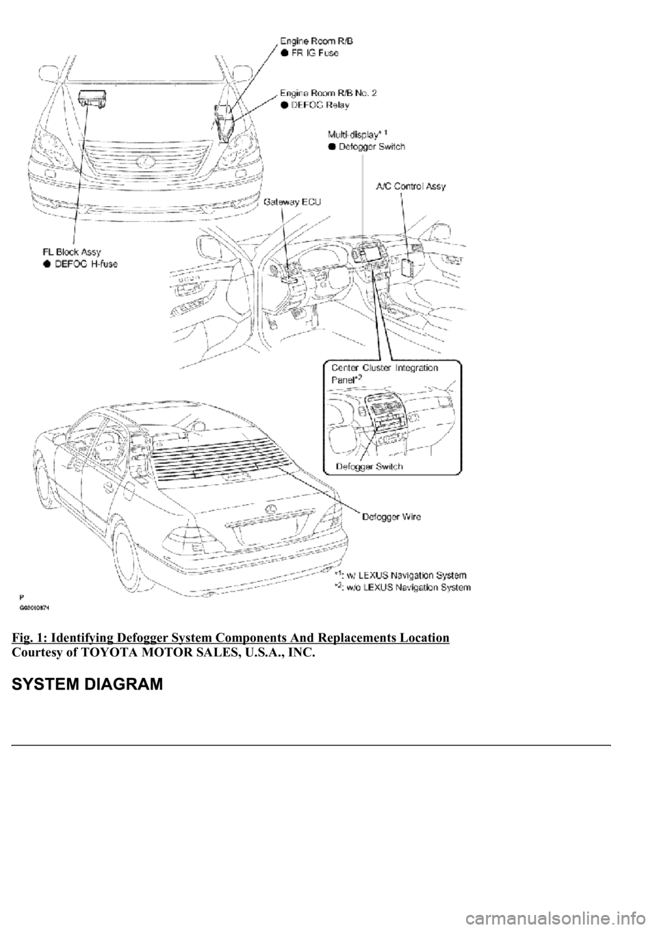
Fig. 1: Identifying Defogger System Components And Replacements Location
Courtesy of TOYOTA MOTOR SALES, U.S.A., INC.
Trending: lock, Ecu, suspension, spark plugs replace, lane assist, park, evap
