LEXUS LS430 2003 Factory Repair Manual
Manufacturer: LEXUS, Model Year: 2003,
Model line: LS430,
Model: LEXUS LS430 2003
Pages: 4500, PDF Size: 87.45 MB
LEXUS LS430 2003 Factory Repair Manual
LS430 2003
LEXUS
LEXUS
https://www.carmanualsonline.info/img/36/57050/w960_57050-0.png
LEXUS LS430 2003 Factory Repair Manual
Trending: cylinder head, wheel bolt torque, cruise control, spare tire, headrest, c1751, OBD port
Page 1961 of 4500
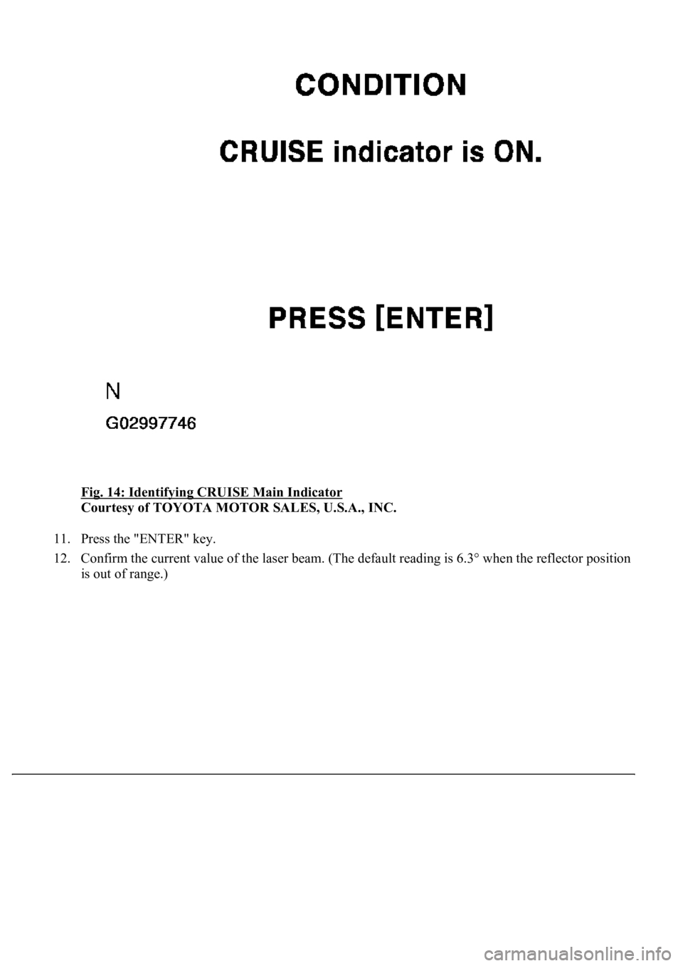
Fig. 14: Identifying CRUISE Main Indicator
Courtesy of TOYOTA MOTOR SALES, U.S.A., INC.
11. Press the "ENTER" key.
12. Confirm the current value of the laser beam. (The default reading is 6.3° when the reflector position
is out of ran
ge.)
Page 1962 of 4500
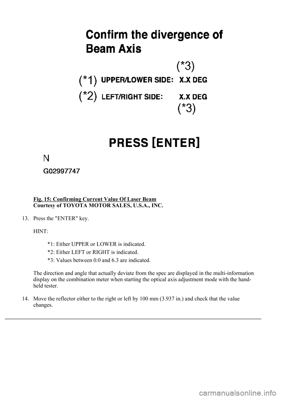
Fig. 15: Confirming Current Value Of Laser Beam
Courtesy of TOYOTA MOTOR SALES, U.S.A., INC.
13. Press the "ENTER" key.
HINT:
*1: Either UPPER or LOWER is indicated.
*2: Either LEFT or RIGHT is indicated.
*3: Values between 0.0 and 6.3 are indicated.
The direction and angle that actually deviate from the spec are displayed in the multi-information
display on the combination meter when starting the optical axis adjustment mode with the hand-
held tester.
14. Move the reflector either to the right or left by 100 mm (3.937 in.) and check that the value
changes.
Page 1963 of 4500
15. Return the reflector to the original position and read the current angle.
DIVERGENCE OF BEAM AXIS TABLE
HINT:
When the values displayed on the screen are normal, the values are within the above range. If the
value is out of range, check the installation condition of the bumper reinforcement, etc.
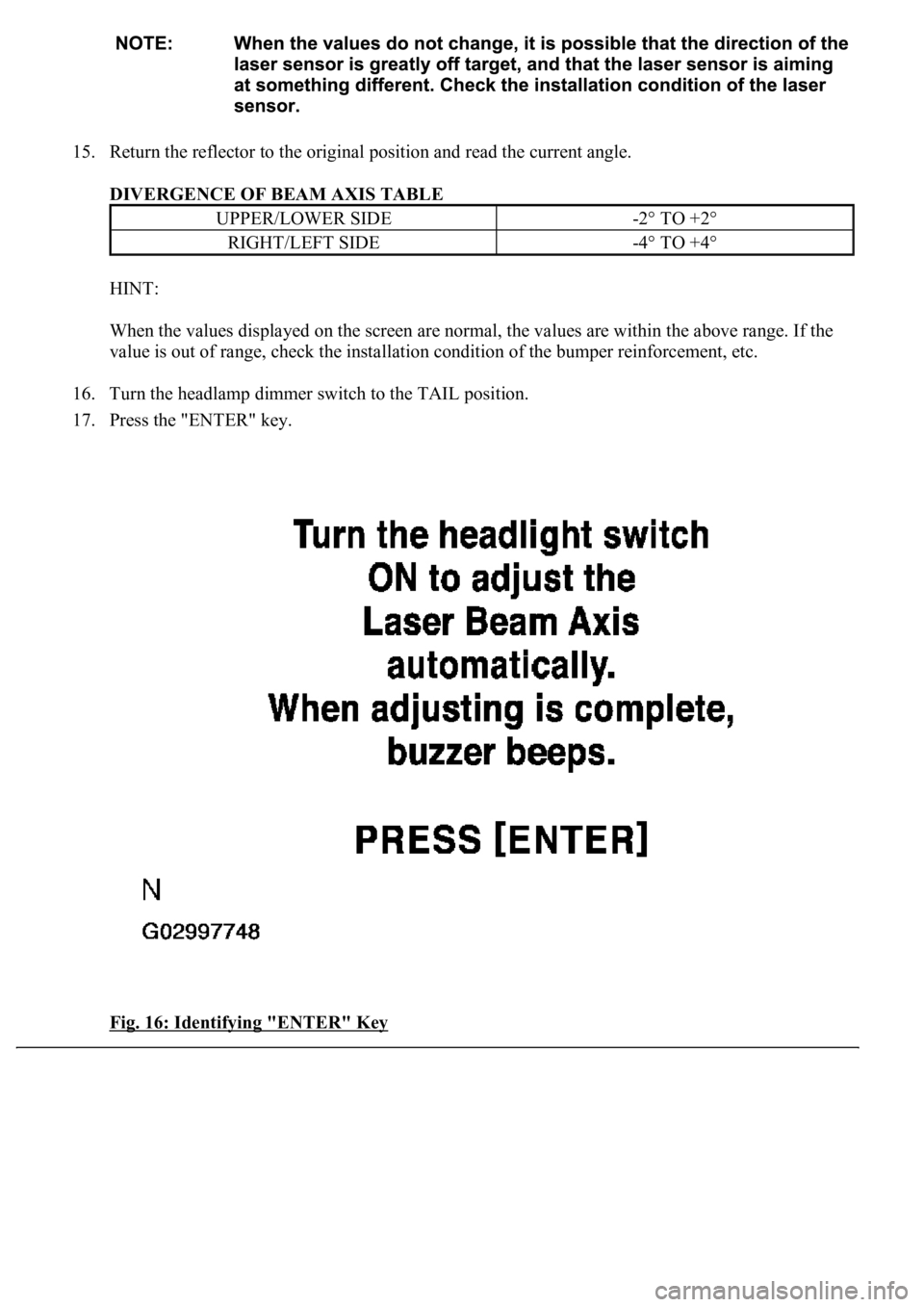
16. Turn the headlamp dimmer switch to the TAIL position.
17. Press the "ENTER" key.
Fig. 16: Identifying "ENTER" Key
UPPER/LOWER SIDE-2° TO +2°
RIGHT/LEFT SIDE-4° TO +4°
Page 1964 of 4500
Courtesy of TOYOTA MOTOR SALES, U.S.A., INC.
18. Beam axis adjustment will be performed automatically.
Fig. 17: Beam Axis Adjustment Screen
Courtesy of TOYOTA MOTOR SALES, U.S.A., INC.
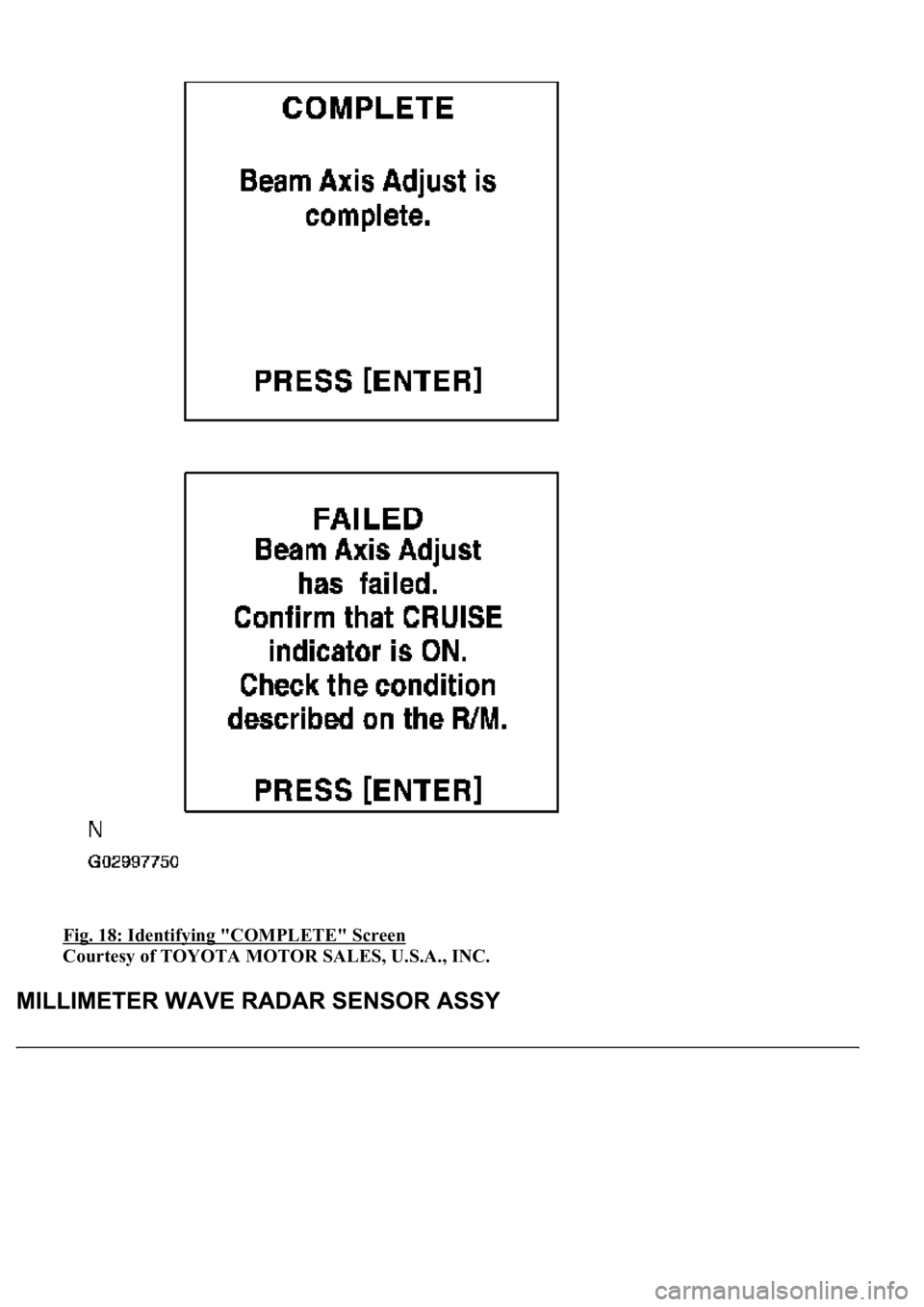
19. When the adjustment is completed, "COMPLETE" is indicated on the screen and the system beeps
for 10 seconds.
Page 1965 of 4500
Fig. 18: Identifying "COMPLETE" Screen
Courtesy of TOYOTA MOTOR SALES, U.S.A., INC.
Page 1966 of 4500
REPLACEMENT
1.SEPARATE BATTERY NEGATIVE TERMINAL
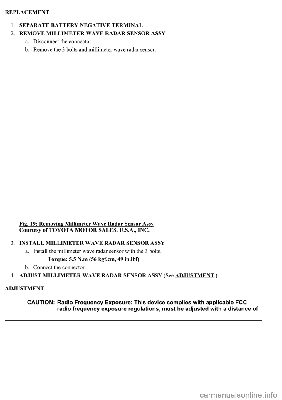
2.REMOVE MILLIMETER WAVE RADAR SENSOR ASSY
a. Disconnect the connector.
b. Remove the 3 bolts and millimeter wave radar sensor.
<0029004c004a001100030014001c001d000300350048005000520059004c0051004a00030030004c004f004f004c005000480057004800550003003a0044005900480003003500440047004400550003003600480051005600520055000300240056005600
5c[
Courtesy of TOYOTA MOTOR SALES, U.S.A., INC.
3.INSTALL MILLIMETER WAVE RADAR SENSOR ASSY
a. Install the millimeter wave radar sensor with the 3 bolts.
Torque: 5.5 N.m (56 kgf.cm, 49 in.lbf)
b. Connect the connector.
4.ADJUST MILLIMETER WAVE RADAR SENSOR ASSY (See ADJUSTMENT
)
ADJUSTMENT
Page 1967 of 4500
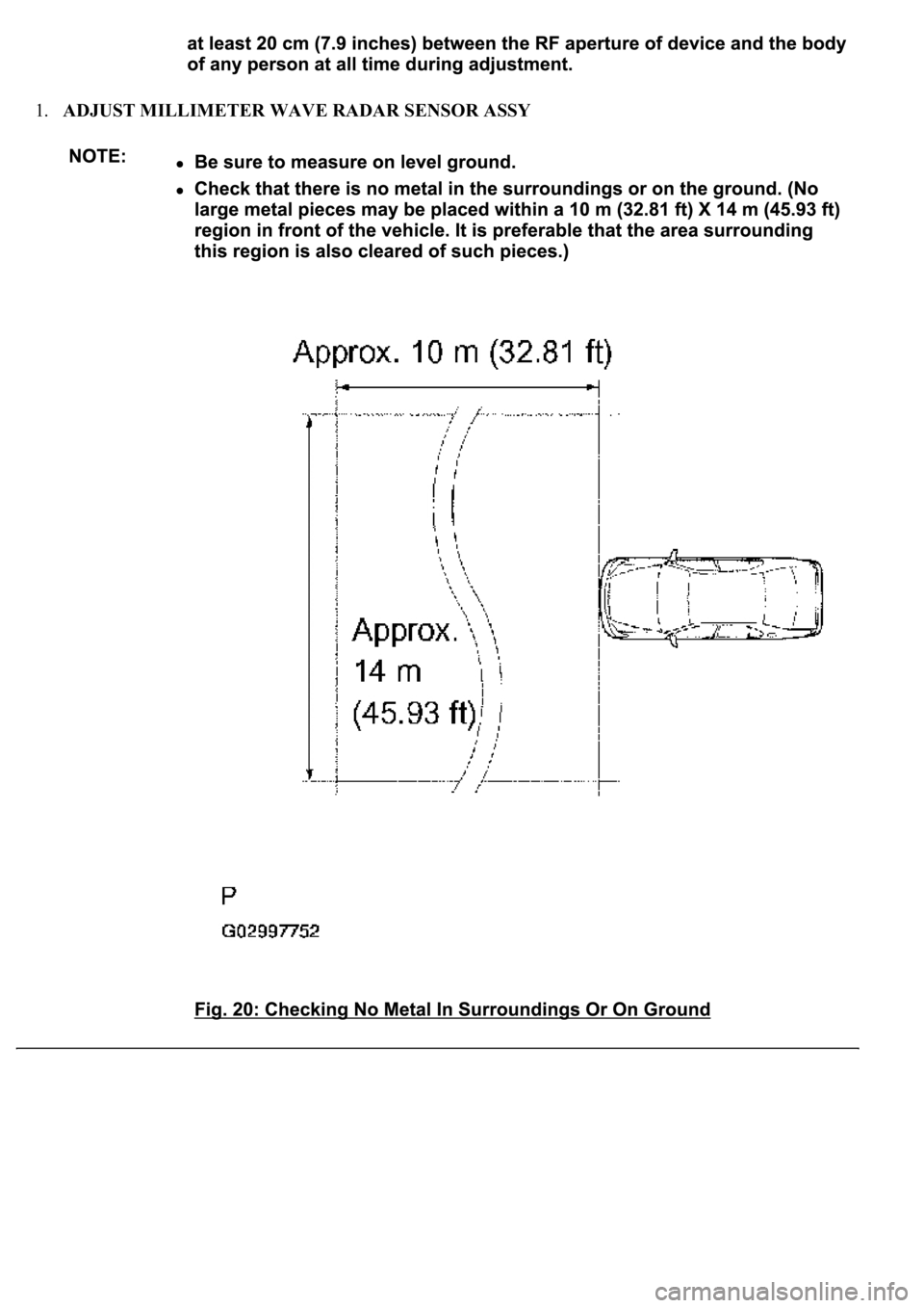
1.ADJUST MILLIMETER WAVE RADAR SENSOR ASSY
Page 1968 of 4500
a. Preparation for adjusting the radar beam axis
1. Adjust the tire pressure properly (see INSPECTION
).
2. Luggage in the vehicle, such as in the trunk, should be unloaded.
b. Adjust the standard vehicle height (vehicle with air suspension) (see INSPECTION
)
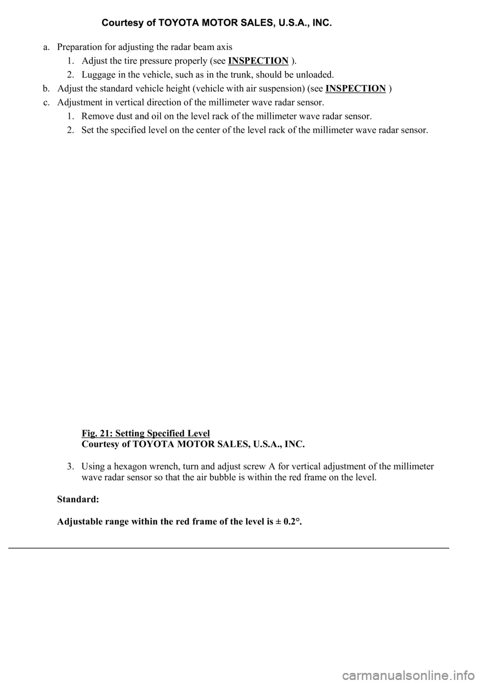
c. Adjustment in vertical direction of the millimeter wave radar sensor.
1. Remove dust and oil on the level rack of the millimeter wave radar sensor.
2. Set the specified level on the center of the level rack of the millimeter wave radar sensor.
Fig. 21: Setting Specified Level
Courtesy of TOYOTA MOTOR SALES, U.S.A., INC.
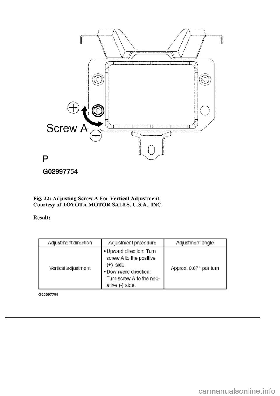
3. Using a hexagon wrench, turn and adjust screw A for vertical adjustment of the millimeter
wave radar sensor so that the air bubble is within the red frame on the level.
Standard:
Adjustable range within the red frame of the level is ± 0.2°.
Page 1969 of 4500
Fig. 22: Adjusting Screw A For Vertical Adjustment
Courtesy of TOYOTA MOTOR SALES, U.S.A., INC.
Result:
Page 1970 of 4500
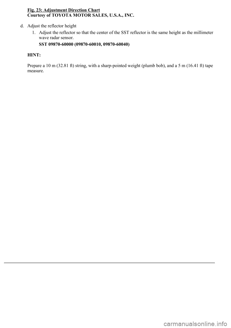
Fig. 23: Adjustment Direction Chart
Courtesy of TOYOTA MOTOR SALES, U.S.A., INC.
d. Adjust the reflector height
1. Adjust the reflector so that the center of the SST reflector is the same height as the millimeter
wave radar sensor.
SST 09870-60000 (09870-60010, 09870-60040)
HINT:
Prepare a 10 m (32.81 ft) string, with a sharp-pointed weight (plumb bob), and a 5 m (16.41 ft) tape
measure.
Trending: tow, set clock, oil type, oxygen sensor, air conditioning, center console, mirror controls
