LEXUS LS430 2003 Factory Repair Manual
Manufacturer: LEXUS, Model Year: 2003,
Model line: LS430,
Model: LEXUS LS430 2003
Pages: 4500, PDF Size: 87.45 MB
LEXUS LS430 2003 Factory Repair Manual
LS430 2003
LEXUS
LEXUS
https://www.carmanualsonline.info/img/36/57050/w960_57050-0.png
LEXUS LS430 2003 Factory Repair Manual
Trending: CD changer, sat nav, wheel torque, headlamp, service indicator, weight, washer fluid
Page 1941 of 4500
OK: When cruise control main switch operation is performed the standard values will be above.
NG: REPLACE ECM (SEE REPLACEMENT
)
OK: PROCEED TO NEXT CIRCUIT INSPECTION SHOWN ON PROBLEM SYMPTOMS
TABLE
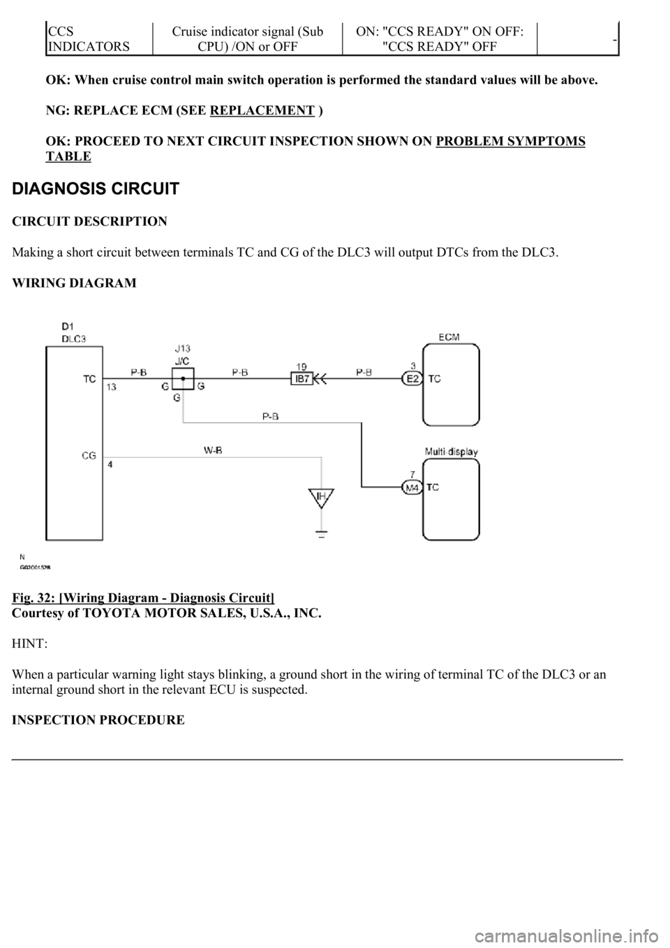
CIRCUIT DESCRIPTION
Making a short circuit between terminals TC and CG of the DLC3 will output DTCs from the DLC3.
WIRING DIAGRAM
Fig. 32: [Wiring Diagram
- Diagnosis Circuit]
Courtesy of TOYOTA MOTOR SALES, U.S.A., INC.
HINT:
When a particular warning light stays blinking, a ground short in the wiring of terminal TC of the DLC3 or an
internal ground short in the relevant ECU is suspected.
INSPECTION PROCEDURE
CCS
INDICATORSCruise indicator signal (Sub
CPU) /ON or OFFON: "CCS READY" ON OFF:
"CCS READY" OFF-
Page 1942 of 4500
1.CHECK HARNESS AND CONNECTOR (TC of DLC3 - ECM)
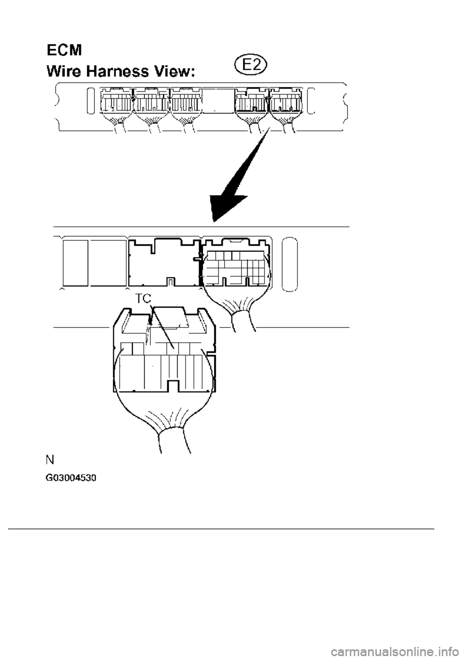
a. Disconnect the E2 connector from the ECM.
b. Measure the resistance according to the value(s) in the table below.
DLC3 CONNECTOR TERMINALS RESISTANCE SPECIFICATION
Fig. 33: Identifying DLC3 Connector Terminals
Courtesy of TOYOTA MOTOR SALES, U.S.A., INC.
Tester connectionConditionSpecified condition
TC (E2-3) - TC (D1 - 13)AlwaysBelow 1 ohms
Page 1943 of 4500
Page 1944 of 4500
Fig. 34: Disconnecting E2 Connector From ECM
Courtesy of TOYOTA MOTOR SALES, U.S.A., INC.
NG: REPAIR OR REPLACE HARNESS OR CONNECTOR (DLC3 - ECM)
OK: Go to next step
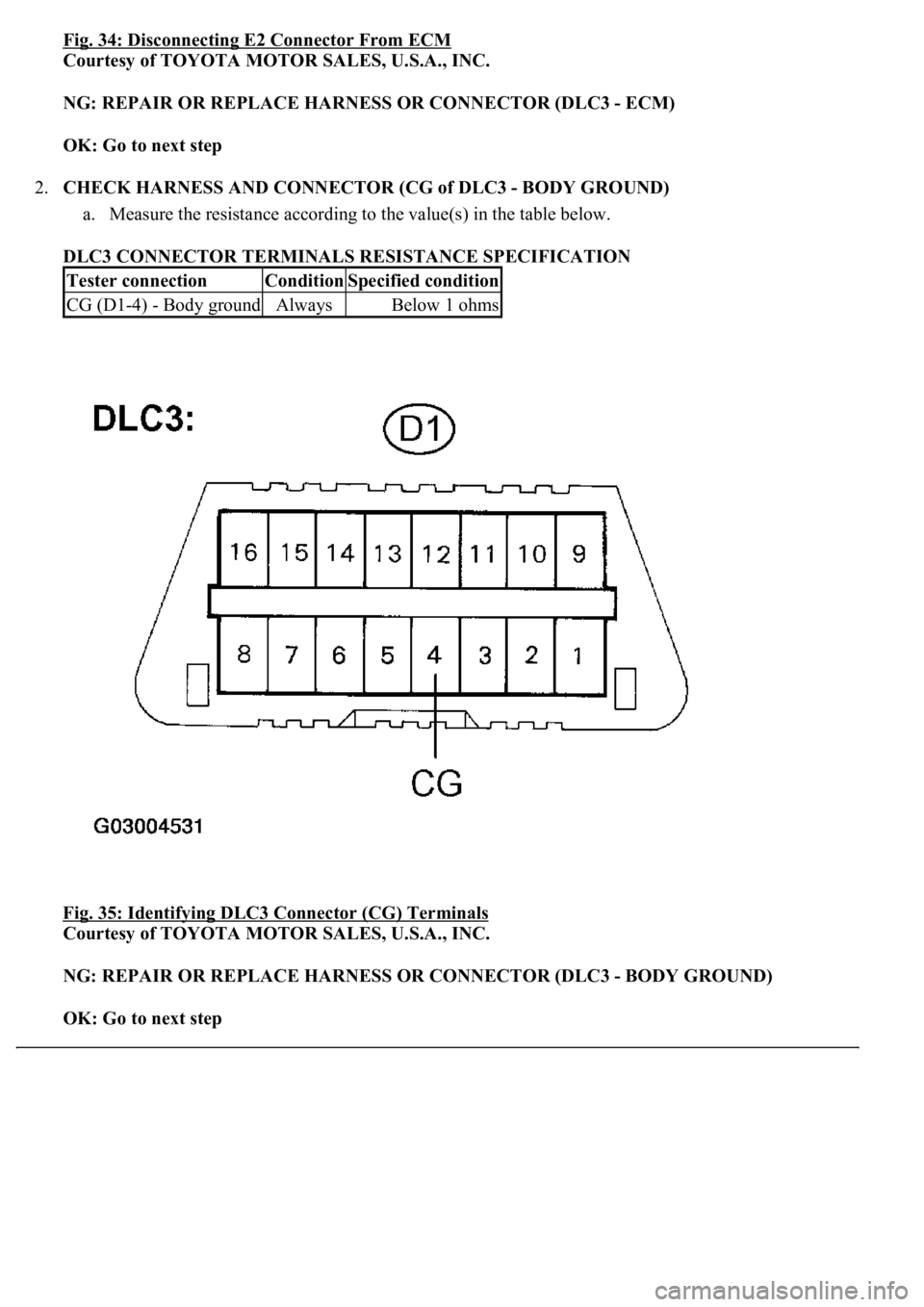
2.CHECK HARNESS AND CONNECTOR (CG of DLC3 - BODY GROUND)
a. Measure the resistance according to the value(s) in the table below.
DLC3 CONNECTOR TERMINALS RESISTANCE SPECIFICATION
Fig. 35: Identifying DLC3 Connector (CG) Terminals
Courtesy of TOYOTA MOTOR SALES, U.S.A., INC.
NG: REPAIR OR REPLACE HARNESS OR CONNECTOR (DLC3 - BODY GROUND)
OK: Go to next step
Tester connectionConditionSpecified condition
CG (D1-4) - Body groundAlwaysBelow 1 ohms
Page 1945 of 4500
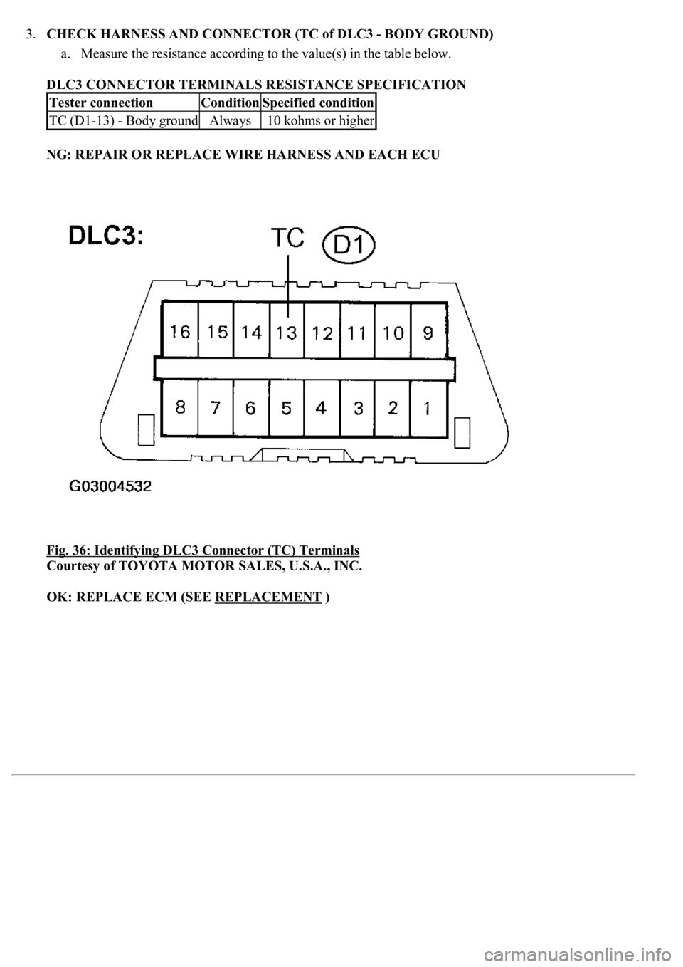
3.CHECK HARNESS AND CONNECTOR (TC of DLC3 - BODY GROUND)
a. Measure the resistance according to the value(s) in the table below.
DLC3 CONNECTOR TERMINALS RESISTANCE SPECIFICATION
NG: REPAIR OR REPLACE WIRE HARNESS AND EACH ECU
Fig. 36: Identifying DLC3 Connector (TC) Terminals
Courtesy of TOYOTA MOTOR SALES, U.S.A., INC.
OK: REPLACE ECM (SEE REPLACEMENT
)
Tester connectionConditionSpecified condition
TC (D1-13) - Body groundAlways10 kohms or higher
Page 1946 of 4500
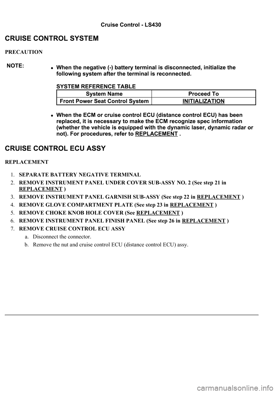
PRECAUTION
REPLACEMENT
1.SEPARATE BATTERY NEGATIVE TERMINAL
2.REMOVE INSTRUMENT PANEL UNDER COVER SUB-ASSY NO. 2 (See step 21 in
REPLACEMENT
)
3.REMOVE INSTRUMENT PANEL GARNISH SUB-ASSY (See step 22 in REPLACEMENT
)
4.REMOVE GLOVE COMPARTMENT PLATE (See step 23 in REPLACEMENT
)
5.REMOVE CHOKE KNOB HOLE COVER (See REPLACEMENT
)
6.REMOVE INSTRUMENT PANEL FINISH PANEL (See step 26 in REPLACEMENT
)
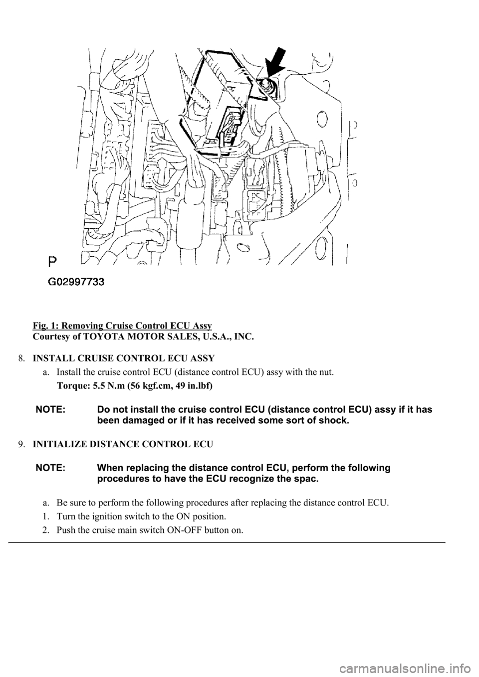
7.REMOVE CRUISE CONTROL ECU ASSY
a. Disconnect the connector.
b. Remove the nut and cruise control ECU (distance control ECU) assy.
Page 1947 of 4500
Fig. 1: Removing Cruise Control ECU Assy
Courtesy of TOYOTA MOTOR SALES, U.S.A., INC.
8.INSTALL CRUISE CONTROL ECU ASSY
a. Install the cruise control ECU (distance control ECU) assy with the nut.
Torque: 5.5 N.m (56 kgf.cm, 49 in.lbf)
9.INITIALIZE DISTANCE CONTROL ECU
a. Be sure to perform the following procedures after replacing the distance control ECU.
1. Turn the ignition switch to the ON position.
2. Push the cruise main switch ON-OFF button on.
Page 1948 of 4500
3. With the brake pedal depressed, push the cruise control main switch to RES/ACC 3 times within 3
seconds. Check that the VSC buzzer sounds at this time.
REPLACEMENT
1.SEPARATE BATTERY NEGATIVE TERMINAL
2.REMOVE ENGINE UNDER COVER NO. 1 (See REPLACEMENT
)
3.REMOVE FRONT WHEEL OPENING EXTENSION PAD LH (See REPLACEMENT
)
4.REMOVE FRONT FENDER LINER LH (See REPLACEMENT
)
5.REMOVE FRONT WHEEL OPENING EXTENSION PAD RH (See REPLACEMENT
)
6.REMOVE FRONT FENDER LINER RH (See REPLACEMENT
)
7.REMOVE FRONT BUMPER COVER (See step 5 in REPLACEMENT
)
8.REMOVE FRONT BUMPER REINFORCEMENT SUB-ASSY (See step 9 in REPLACEMENT
)
9.REMOVE LASER SENSOR
a. Disconnect the connector and remove the laser sensor.
Page 1949 of 4500
Fig. 2: Removing Laser Sensor
Courtesy of TOYOTA MOTOR SALES, U.S.A., INC.
10.INSTALL LASER SENSOR
11.INSTALL FRONT BUMPER REINFORCEMENT SUB-ASSY (See step 25 in REPLACEMENT
)
12.ADJUST FOG LIGHT AIM (See ADJUSTMENT
)
13.CHECK FOG LIGHT AIM
14.ADJUST LASER SENSOR (See ADJUSTMENT
)
ADJUSTMENT
Page 1950 of 4500
HINT:
There is a limitation on laser optical axis adjustment.
Since the laser sensor is installed in the bumper reinforcement, it is important that the laser sensor,
bumper reinforcement, and other related parts are installed properly.
When the sensor is removed from the vehicle for trouble diagnosis or repair, it is necessary to adjust the
laser optical axis after the operation.
1.ADJUST LASER SENSOR
a. Preparation for adjusting the laser optical axis
1. Adjust the tire pressure properly (see INSPECTION
).
2. Luggage in the vehicle, such as in the trunk, should be unloaded.
3. Clean the light-luminous and light-receiving portions of the laser sensor.
HINT:
Prepare a 10 m (32.81 ft) string, with a sharp-pointed weight (plumb bob), and a 5 m (16.41 ft) tape
measure.
Trending: fuel pump, battery capacity, change time, Manifold gasket, B2799, immobilizer, child lock
