check engine LEXUS LS430 2003 Factory User Guide
[x] Cancel search | Manufacturer: LEXUS, Model Year: 2003, Model line: LS430, Model: LEXUS LS430 2003Pages: 4500, PDF Size: 87.45 MB
Page 94 of 4500
NG: REPAIR OR REPLACE HARNESS OR CONNECTOR
OK: Go to next step
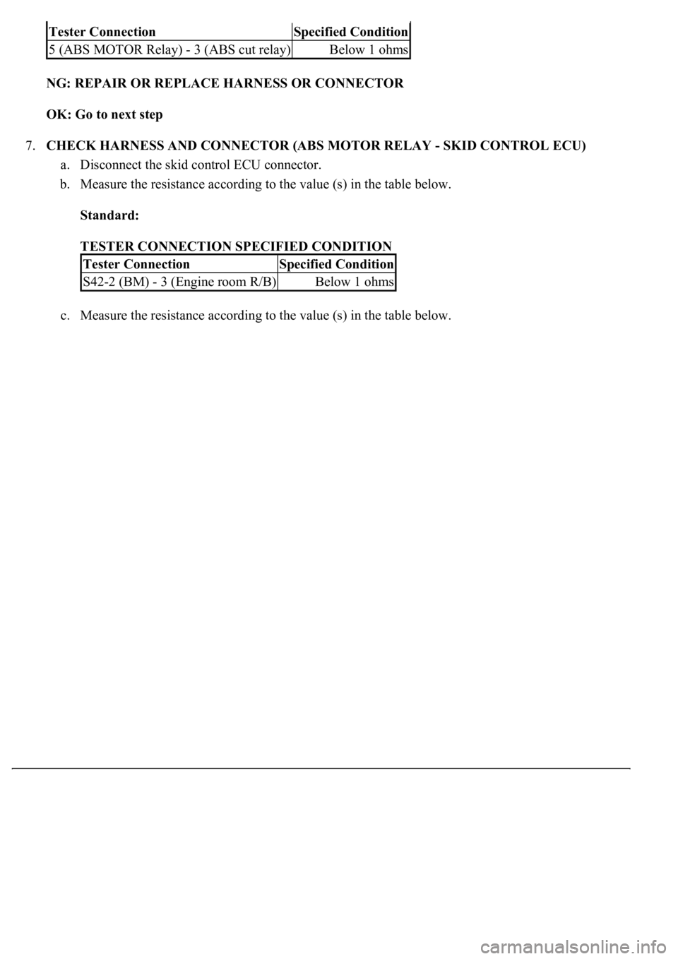
7.CHECK HARNESS AND CONNECTOR (ABS MOTOR RELAY - SKID CONTROL ECU)
a. Disconnect the skid control ECU connector.
b. Measure the resistance according to the value (s) in the table below.
Standard:
TESTER CONNECTION SPECIFIED CONDITION
c. Measure the resistance accordin
g to the value (s) in the table below.
Tester ConnectionSpecified Condition
5 (ABS MOTOR Relay) - 3 (ABS cut relay)Below 1 ohms
Tester ConnectionSpecified Condition
S42-2 (BM) - 3 (Engine room R/B)Below 1 ohms
Page 102 of 4500

HINT:
It is suspect that the DTCs output was caused by the poor connection on the connector terminal.
OK: REPLACE ABS & TRACTION ACTUATOR ASSY (SEE REPLACEMENT
)
CIRCUIT DESCRIPTION
If trouble occurs in the engine control system, the ECM transmits the abnormality to the skid control ECU. The
skid control ECU sets this DTC and the skid control ECU prohibits TRAC and VSC control.
DTC DETECTING CONDITION DESCRIPTION
INSPECTION PROCEDURE
1.CHECK HARNESS AND CONNECTOR (MOMENTARY INTERRUPTION)
a. Using the hand-held tester, check for any momentary interruption in the wire harness and connector
corresponding to a DTC (see CHECK FOR INTERMITTENT PROBLEMS
).
MEASUREMENT ITEM / RANGE (DISPLAY) DESCRIPTION
OK: Go to next step
There are no momentary interruptions.
HINT:
Perform the above inspection before removing the sensor and connector.
NG: REPAIR OR REPLACE HARNESS OR CONNECTOR (ECM - SKID CONTROL ECU)
OK: Go to next step
2.CHECK DTC FOR ENGINE
a. Check if the normal code is recorded for en
gine control system.
DTC No.DTC Detecting ConditionTrouble Area
C1201/51At the engine speed of 500 RPM, a trouble signal in the engine
control system continues for 5 secs, or more.Engine control
system
ItemMeasurement Item / Range (Display)Normal Condition
EFI COMEFI communication open detectionOPEN: Momentary interruption
Page 108 of 4500
When U0121/94, U0123/62, U0124/95 or U0126/63 are output together with C1231/31, inspect and
repair the trouble areas indicated by U0121/94, U0123/62, U0124/95 or U0126/63 first.
When the speed sensor or the yaw rate sensor has trouble, DTCs for the steering angle sensor may be
output even when the steering angle sensor is normal. When DTCs for the speed sensor or yaw rate
sensor are output together with other DTCs for the steering angle sensor, inspect and repair the speed
sensor and yaw rate sensor first, and then inspect and repair the steering angle sensor.
1.CHECK HARNESS AND CONNECTOR (MOMENTARY INTERRUPTION)
a. Using the hand-held tester, check for any momentary interruption in the wire harness and
connectors between the skid control ECU and steering angle sensor (see CHECK FOR
INTERMITTENT PROBLEMS ).
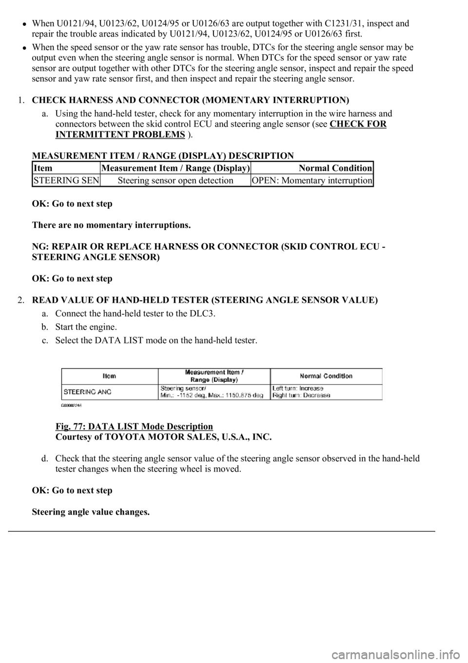
MEASUREMENT ITEM / RANGE (DISPLAY) DESCRIPTION
OK: Go to next step
There are no momentary interruptions.
NG: REPAIR OR REPLACE HARNESS OR CONNECTOR (SKID CONTROL ECU -
STEERING ANGLE SENSOR)
OK: Go to next step
2.READ VALUE OF HAND-HELD TESTER (STEERING ANGLE SENSOR VALUE)
a. Connect the hand-held tester to the DLC3.
b. Start the engine.
c. Select the DATA LIST mode on the hand-held tester.
Fig. 77: DATA LIST Mode Description
Courtesy of TOYOTA MOTOR SALES, U.S.A., INC.
d. Check that the steering angle sensor value of the steering angle sensor observed in the hand-held
tester changes when the steering wheel is moved.
OK: Go to next step
Steering angle value changes.
ItemMeasurement Item / Range (Display)Normal Condition
STEERING SENSteering sensor open detectionOPEN: Momentary interruption
Page 125 of 4500

OK: Go to next step
2.INSPECT BATTERY
a. Check the battery voltage.
Standard:
Voltage: 10 to 14 V
NG: INSPECT CHARGING SYSTEM (SEE ON
-VEHICLE INSPECTION )
OK: Go to next step
3.INSPECT SKID CONTROL ECU TERMINAL VOLTAGE (IG1 TERMINAL)
a. Connect the hand-held tester to the DLC3.
b. Start the engine.
c. Select the DATA LIST mode on the hand-held tester.
Fig. 91: DATA LIST Mode Description
Courtesy of TOYOTA MOTOR SALES, U.S.A., INC.
d. Read the voltage condition output from the ECU displayed on the hand-held tester.
Standard:
"Normal" is displayed.
NG: Go to step 4
OK: REPLACE ABS & TRACTION ACTUATOR ASSY (SEE REPLACEMENT
)
4.INSPECT SKID CONTROL ECU CONNECTOR (GND TERMINAL CONTINUITY)
a. Disconnect the skid control ECU connector.
b. Measure the resistance according to the value (s) in the table below.
Standard:
Page 141 of 4500
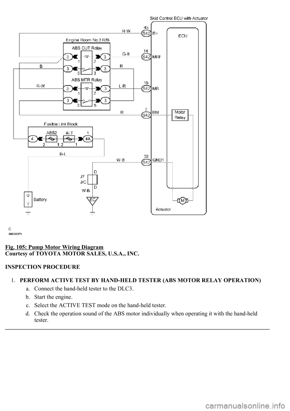
Fig. 105: Pump Motor Wiring Diagram
Courtesy of TOYOTA MOTOR SALES, U.S.A., INC.
INSPECTION PROCEDURE
1.PERFORM ACTIVE TEST BY HAND-HELD TESTER (ABS MOTOR RELAY OPERATION)
a. Connect the hand-held tester to the DLC3.
b. Start the engine.
c. Select the ACTIVE TEST mode on the hand-held tester.
d. Check the operation sound of the ABS motor individually when operating it with the hand-held
tester.
Page 150 of 4500
INSPECTION PROCEDURE
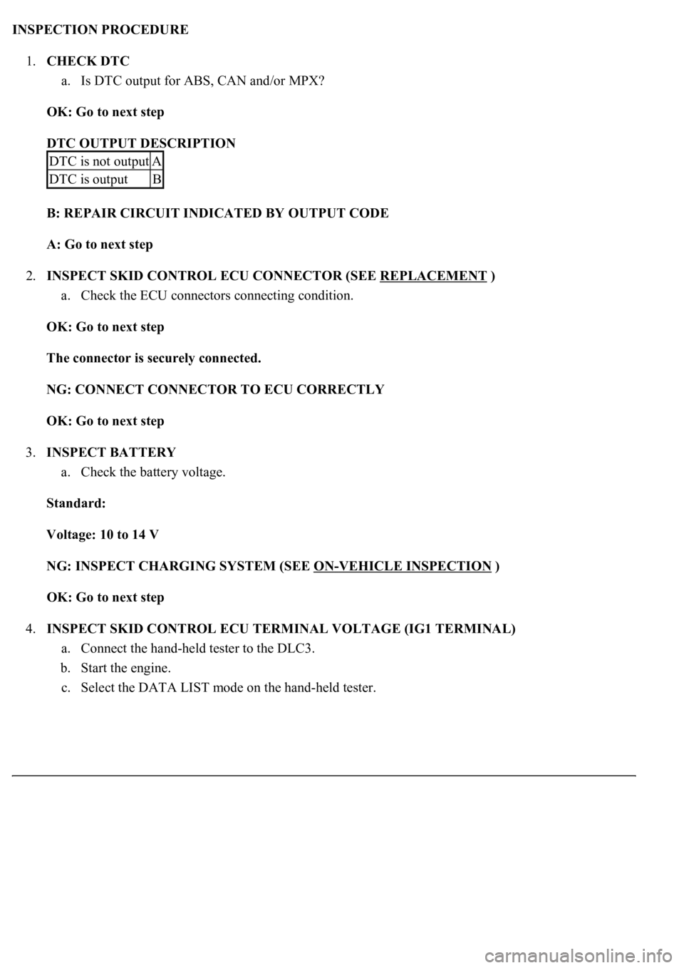
1.CHECK DTC
a. Is DTC output for ABS, CAN and/or MPX?
OK: Go to next step
DTC OUTPUT DESCRIPTION
B: REPAIR CIRCUIT INDICATED BY OUTPUT CODE
A: Go to next step
2.INSPECT SKID CONTROL ECU CONNECTOR (SEE REPLACEMENT
)
a. Check the ECU connectors connecting condition.
OK: Go to next step
The connector is securely connected.
NG: CONNECT CONNECTOR TO ECU CORRECTLY
OK: Go to next step
3.INSPECT BATTERY
a. Check the battery voltage.
Standard:
Voltage: 10 to 14 V
NG: INSPECT CHARGING SYSTEM (SEE ON
-VEHICLE INSPECTION )
OK: Go to next step
4.INSPECT SKID CONTROL ECU TERMINAL VOLTAGE (IG1 TERMINAL)
a. Connect the hand-held tester to the DLC3.
b. Start the engine.
c. Select the DATA LIST mode on the han
d-held tester.
DTC is not outputA
DTC is outputB
Page 154 of 4500

a. Is the DTC output for CAN communication system?
Result:
DTC OUTPUT DESCRIPTION
B: REPAIR CAN COMMUNICATION SYSTEM (SEE PRECAUTION
)
A: Go to next step
2.INSPECT MULTIPLEX COMMUNICATION SYSTEM
a. Is the DTC output for Multiplex communication system?
Result:
DTC OUTPUT DESCRIPTION
B: REPAIR MULTIPLEX COMMUNICATION SYSTEM (SEE DIAGNOSTIC TROUBLE
CODE CHART )
A: Go to next step
3.INSPECT ABS WARNING LIGHT
a. Connect the hand-held tester to the DLC3 and start the engine.
b. Select the item "ABS WARN LIGHT" in the ACTIVE TEST and operate the ABS warning light on
the hand-held tester.
VEHICLE CONDITION / TEST DETAILS
c. Check that "ON" and "OFF" of the ABS warning light can be shown on the combination meter by
the hand-held tester.
Standard:
Turn the ABS warning light ON or OFF in accordance with the hand-held tester.
NG: CHECK AND REPAIR ABS WARNING LIGHT CIRCUIT
OK: REPLACE ABS & TRACTION ACTUATOR ASSY (SEE REPLACEMENT
)
DTC is not outputA
DTC is outputB
DTC is not outputA
DTC is outputB
ItemVehicle Condition / Test DetailsDiagnostic Note
ABS WARN LIGHTTurns ABS warning light ON / OFFObserve combination meter
Page 157 of 4500
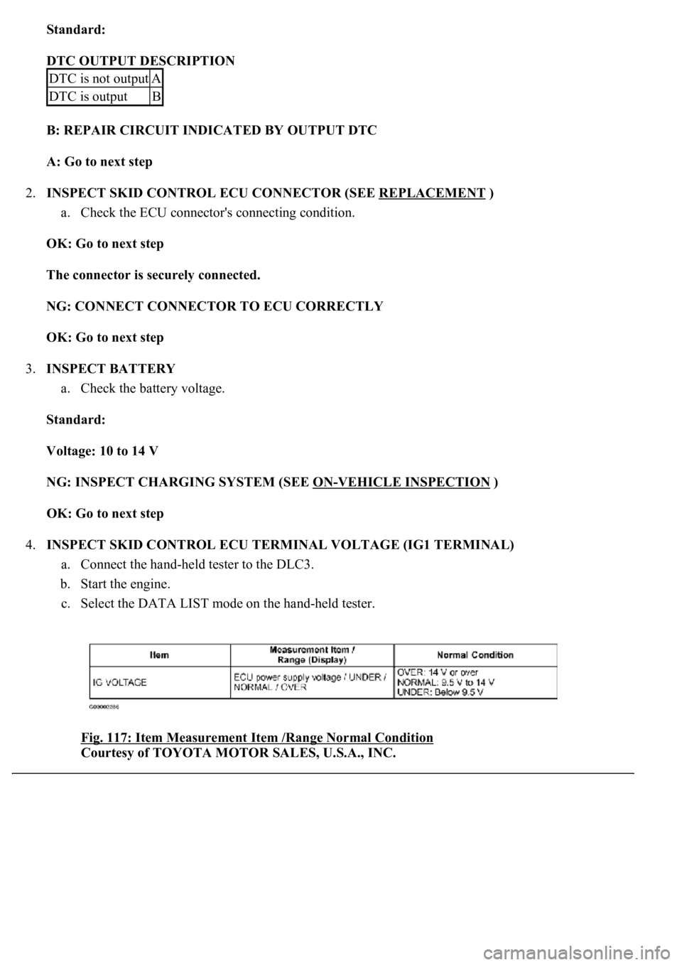
Standard:
DTC OUTPUT DESCRIPTION
B: REPAIR CIRCUIT INDICATED BY OUTPUT DTC
A: Go to next step
2.INSPECT SKID CONTROL ECU CONNECTOR (SEE REPLACEMENT
)
a. Check the ECU connector's connecting condition.
OK: Go to next step
The connector is securely connected.
NG: CONNECT CONNECTOR TO ECU CORRECTLY
OK: Go to next step
3.INSPECT BATTERY
a. Check the battery voltage.
Standard:
Voltage: 10 to 14 V
NG: INSPECT CHARGING SYSTEM (SEE ON
-VEHICLE INSPECTION )
OK: Go to next step
4.INSPECT SKID CONTROL ECU TERMINAL VOLTAGE (IG1 TERMINAL)
a. Connect the hand-held tester to the DLC3.
b. Start the engine.
c. Select the DATA LIST mode on the hand-held tester.
Fig. 117: Item Measurement Item /Range Normal Condition
Courtesy of TOYOTA MOTOR SALES, U.S.A., INC.
DTC is not outputA
DTC is outputB
Page 161 of 4500

Result:
DTC OUTPUT DESCRIPTION
B: REPAIR CAN COMMUNICATION SYSTEM (SEE PRECAUTION
)
A: Go to next step
2.INSPECT MULTIPLEX COMMUNICATION SYSTEM
a. Is the DTC output for Multiplex communication system?
Result:
DTC OUTPUT DESCRIPTION
B: REPAIR MULTIPLEX COMMUNICATION SYSTEM (SEE DIAGNOSTIC TROUBLE
CODE CHART )
A: Go to next step
3.CHECK MULTI INFORMATION DISPLAY (VSC WARNING)
a. Connect the hand-held tester to the DLC3 and start the engine.
b. Select the item "VSC WARN LIGHT" in the ACTIVE TEST and operate the VSC warning light on
the hand-held tester.
VEHICLE CONDITION / TEST DETAILS
c. Check that "ON" and "OFF" of the VSC warning light are indicated on the combination meter
when using the hand-held tester.
OK: Go to next step
Turn the VSC warning light ON or OFF in accordance with the hand-held tester.
NG: CHECK AND REPAIR VSC WARNING LIGHT CIRCUIT
OK: REPLACE ABS & TRACTION ACTUATOR ASSY (SEE REPLACEMENT
)
DTC is not outputA
DTC is outputB
DTC is not outputA
DTC is outputB
ItemVehicle Condition / Test DetailsDiagnostic Note
VSC WARN LIGHTTurns VSC warning light ON / OFFObserve combination meter
Page 165 of 4500

INSPECTION PROCEDURE
HINT:
When releasing the parking brake, set the chocks to hold the vehicle for safety.
Check that "Brake Wear" does not appear on the multi-information display.
If it appears, check that brake pad thickness and replace the pad as necessary.
1.CHECK BRAKE FLUID LEVEL IN RESERVOIR
a. Check that the brake fluid level is proper.
OK: Go to next step
Brake fluid level is proper.
NG: ADD BRAKE FLUID
OK: Go to next step
2.CHECK DTC
a. Are the DTC recorded for ABS, VSC, CAN and/or Multiplex communication system?
OK: Go to next step
DTC OUTPUT DESCRIPTION
B: REPAIR CIRCUIT INDICATED BY OUTPUT CODE
A: Go to next step
3.INSPECT BRAKE WARNING LIGHT
a. Connect the hand-held tester to the DLC3.
b. Start the engine.
c. Select the item "BRAKE WARN LIGHT" in the ACTIVE TEST and operate the BRAKE warning
light on the hand-held tester.
VEHICLE CONDITION / TEST DETAILS
d. Check that "ON" and "OFF" of the BRAKE warning light are indicated on the combination meter
when usin
g the hand-held tester.
DTC is not outputA
DTC is outputB
ItemVehicle Condition / Test DetailsDiagnostic Note
BRAKE WRN LIGHTTurns BRAKE warning light ON / OFFObserve combination meter