LEXUS LS430 2003 Factory Repair Manual
Manufacturer: LEXUS, Model Year: 2003,
Model line: LS430,
Model: LEXUS LS430 2003
Pages: 4500, PDF Size: 87.45 MB
LEXUS LS430 2003 Factory Repair Manual
LS430 2003
LEXUS
LEXUS
https://www.carmanualsonline.info/img/36/57050/w960_57050-0.png
LEXUS LS430 2003 Factory Repair Manual
Trending: TPMS, warning, Bean, vacuum switch, overheating, brake fluid, diagnostic menu
Page 2221 of 4500
OK: Go to Next Step.
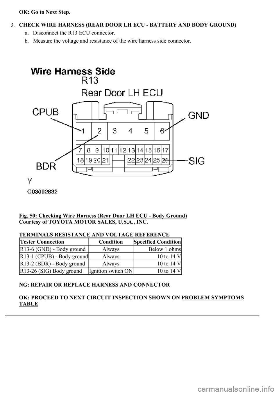
3.CHECK WIRE HARNESS (REAR DOOR LH ECU - BATTERY AND BODY GROUND)
a. Disconnect the R13 ECU connector.
b. Measure the voltage and resistance of the wire harness side connector.
Fig. 50: Checking Wire Harness (Rear Door LH ECU
- Body Ground)
Courtesy of TOYOTA MOTOR SALES, U.S.A., INC.
TERMINALS RESISTANCE AND VOLTAGE REFERENCE
NG: REPAIR OR REPLACE HARNESS AND CONNECTOR
OK: PROCEED TO NEXT CIRCUIT INSPECTION SHOWN ON PROBLEM SYMPTOMS
TABLE
Tester ConnectionConditionSpecified Condition
R13-6 (GND) - Body groundAlwaysBelow 1 ohms
R13-1 (CPUB) - Body groundAlways10 to 14 V
R13-2 (BDR) - Body groundAlways10 to 14 V
R13-26 (SIG) Body groundIgnition switch ON10 to 14 V
Page 2222 of 4500
CIRCUIT DESCRIPTION
This circuit supplies power to operate the rear door RH ECU.
WIRING DIAGRAM
Page 2223 of 4500
Fig. 51: Rear Door RH ECU Power Source Circuit -Wiring Diagram
Courtesy of TOYOTA MOTOR SALES, U.S.A., INC.
INSPECTION PROCEDURE
1.INSPECT FUSE (MPX-IG, AM1, RR DOOR RH, MPX-B1, D/C CUT)
a. Remove the MPX-IG and AM1 fuses from the driver side J/B.
b. Remove the MPX-B1 and RR DOOR RH fuses from the passenger side J/B.
c. Remove the D/C CUT fuse from the FL block assy.
d. Measure the resistance.
Standard: Below 1 ohms
NG: REPLACE FUSE
OK: Go to Next Step.
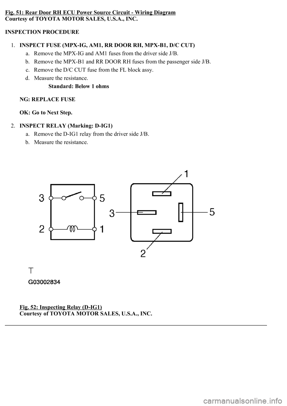
2.INSPECT RELAY (Marking: D-IG1)
a. Remove the D-IG1 relay from the driver side J/B.
b. Measure the resistance.
Fig. 52: Inspecting Relay (D
-IG1)
Courtesy of TOYOTA MOTOR SALES, U.S.A., INC.
Page 2224 of 4500
TERMINALS RESISTANCE REFERENCE
NG: REPLACE RELAY
OK: Go to Next Step.
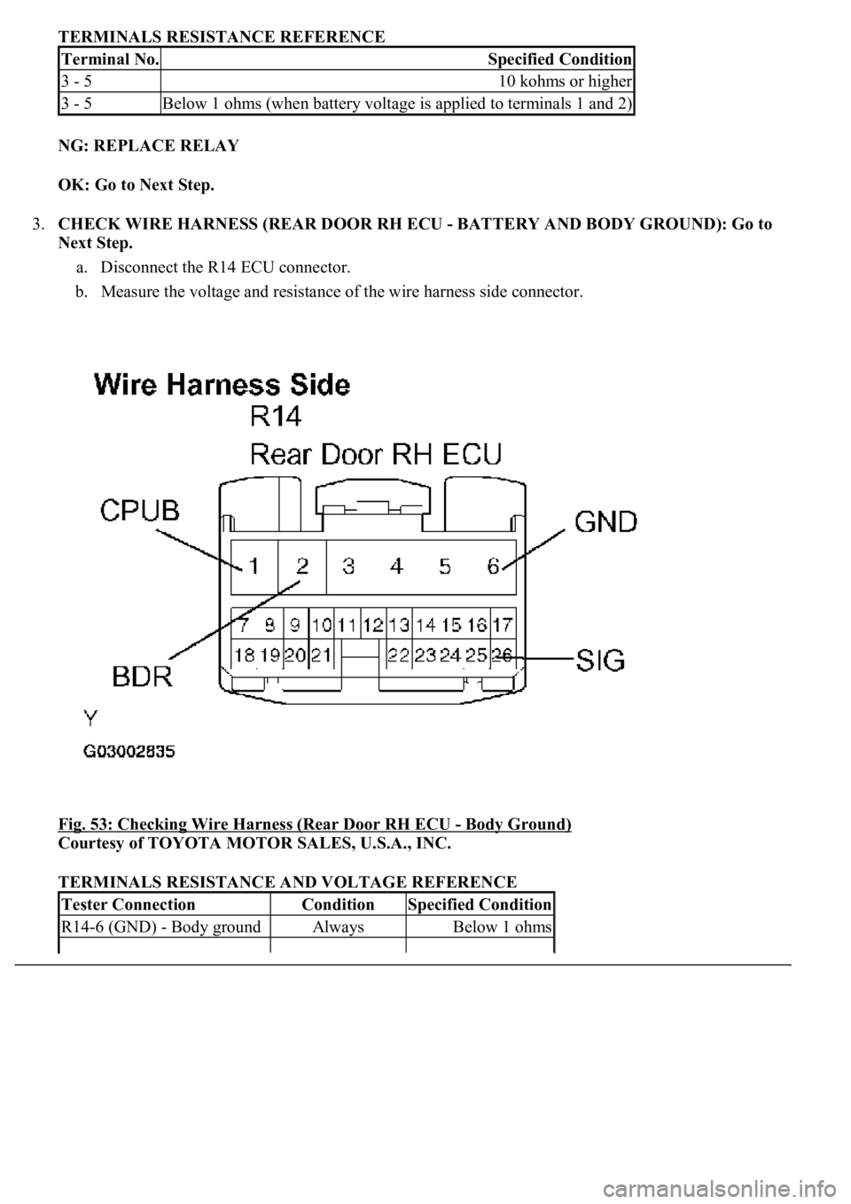
3.CHECK WIRE HARNESS (REAR DOOR RH ECU - BATTERY AND BODY GROUND): Go to
Next Step.
a. Disconnect the R14 ECU connector.
b. Measure the voltage and resistance of the wire harness side connector.
Fig. 53: Checking Wire Harness (Rear Door RH ECU
- Body Ground)
Courtesy of TOYOTA MOTOR SALES, U.S.A., INC.
TERMINALS RESISTANCE AND VOLTAGE REFERENCE
Terminal No.Specified Condition
3 - 510 kohms or higher
3 - 5Below 1 ohms (when battery voltage is applied to terminals 1 and 2)
Tester ConnectionConditionSpecified Condition
R14-6 (GND) - Body groundAlwaysBelow 1 ohms
Page 2225 of 4500
NG: REPAIR OR REPLACE HARNESS AND CONNECTOR
OK: PROCEED TO NEXT CIRCUIT INSPECTION SHOWN ON PROBLEM SYMPTOMS
TABLE
CIRCUIT DESCRIPTION
The door lock assembly has a built-in closer position switch, which detects the position of the closer.
WIRING DIAGRAM
Fig. 54: Door Closer Position Switch Circuit On Driver Side Door
- Wiring Diagram
Courtesy of TOYOTA MOTOR SALES, U.S.A., INC.
INSPECTION PROCEDURE
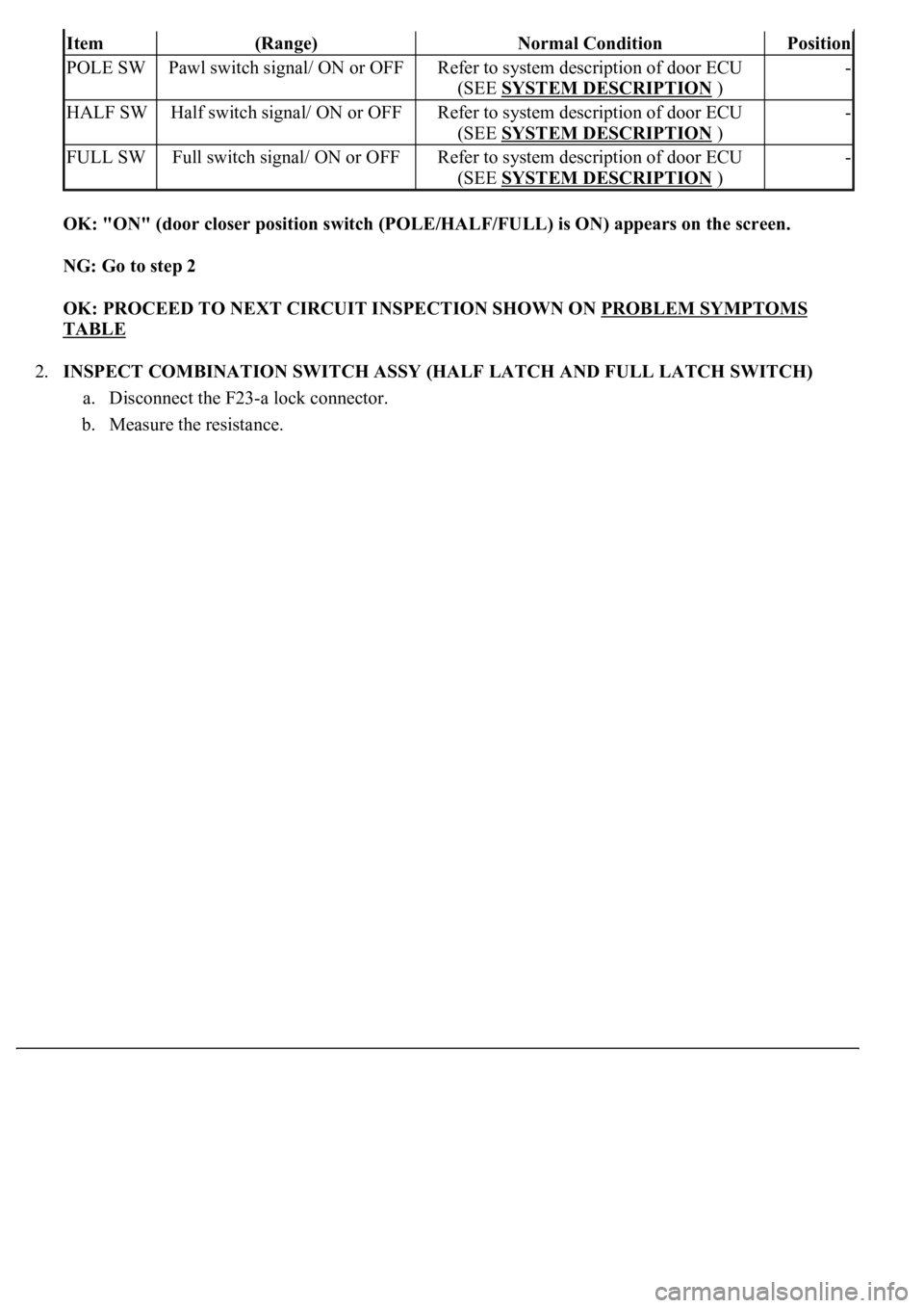
1.READ VALUE OF DATA LIST (DOOR CLOSER POSITION SWITCH (POLE/HALF/ FULL))
a. Check the DATA LIST for proper functioning of the door closer position switch.
DRIVER DOOR EC
R14-1 (CPUB) - Body groundAlways10 to 14 V
R14-2 (BDR) - Body groundAlways10 to 14 V
R14-26 (SIG) Body groundIgnition switch ON10 to 14 V
Measurement item / Display
Page 2226 of 4500
OK: "ON" (door closer position switch (POLE/HALF/FULL) is ON) appears on the screen.
NG: Go to step 2
OK: PROCEED TO NEXT CIRCUIT INSPECTION SHOWN ON PROBLEM SYMPTOMS
TABLE
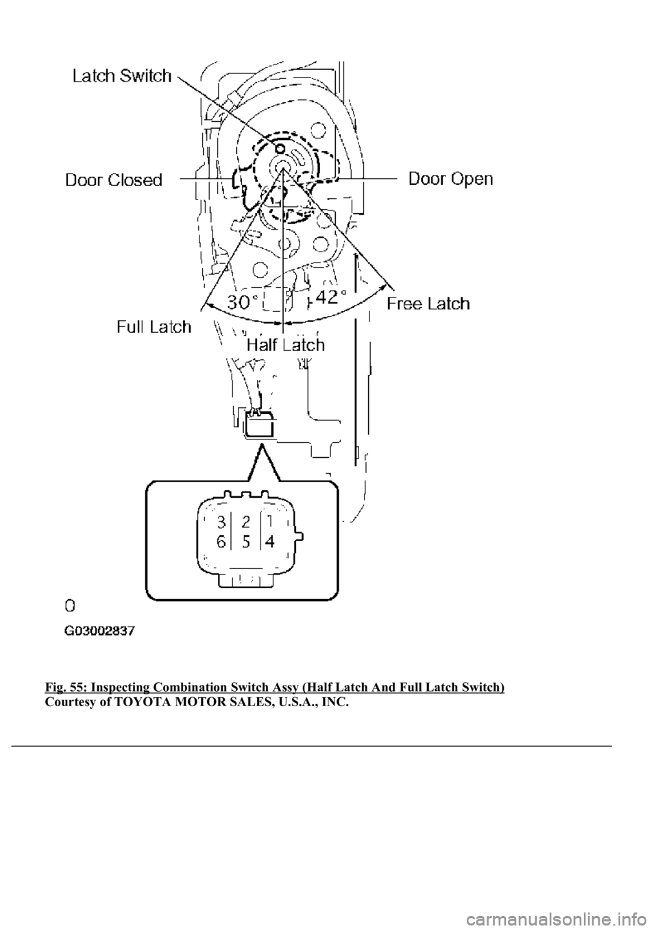
2.INSPECT COMBINATION SWITCH ASSY (HALF LATCH AND FULL LATCH SWITCH)
a. Disconnect the F23-a lock connector.
b. Measure the resistance.
Item(Range)Normal ConditionPosition
POLE SWPawl switch signal/ ON or OFFRefer to system description of door ECU
(SEE SYSTEM DESCRIPTION
)
-
HALF SWHalf switch signal/ ON or OFFRefer to system description of door ECU
(SEE SYSTEM DESCRIPTION
)
-
FULL SWFull switch signal/ ON or OFFRefer to system description of door ECU
(SEE SYSTEM DESCRIPTION
)
-
Page 2227 of 4500
Fig. 55: Inspecting Combination Switch Assy (Half Latch And Full Latch Switch)
Courtesy of TOYOTA MOTOR SALES, U.S.A., INC.
Page 2228 of 4500
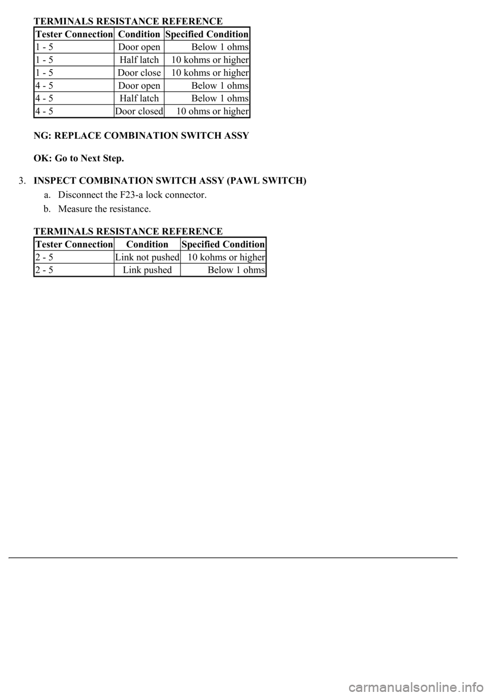
TERMINALS RESISTANCE REFERENCE
NG: REPLACE COMBINATION SWITCH ASSY
OK: Go to Next Step.
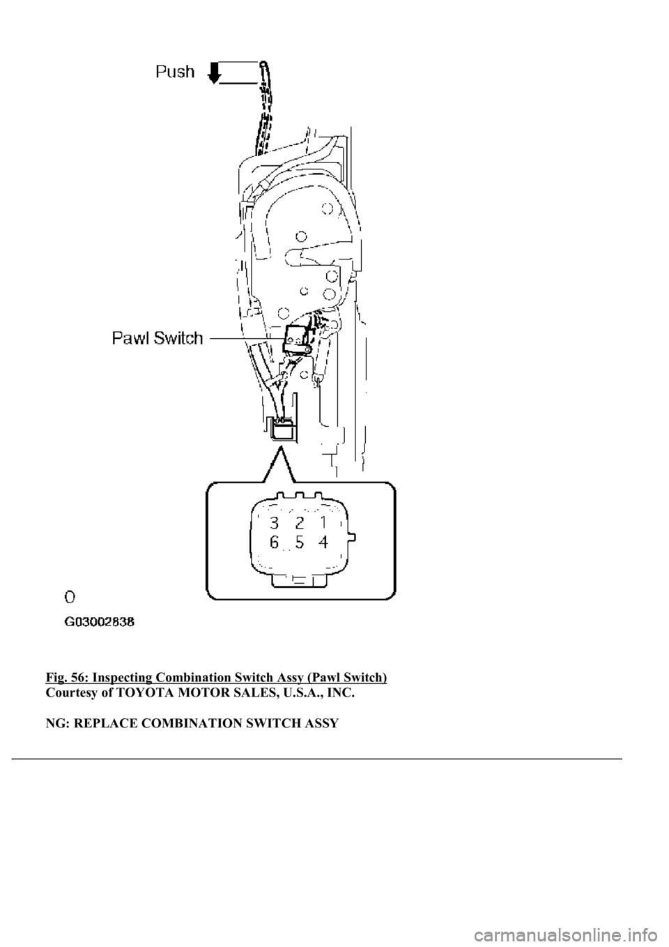
3.INSPECT COMBINATION SWITCH ASSY (PAWL SWITCH)
a. Disconnect the F23-a lock connector.
b. Measure the resistance.
TERMINALS RESISTANCE REFERENCE
Tester ConnectionConditionSpecified Condition
1 - 5Door openBelow 1 ohms
1 - 5Half latch10 kohms or higher
1 - 5Door close10 kohms or higher
4 - 5Door openBelow 1 ohms
4 - 5Half latchBelow 1 ohms
4 - 5Door closed10 ohms or higher
Tester ConnectionConditionSpecified Condition
2 - 5Link not pushed10 kohms or higher
2 - 5Link pushedBelow 1 ohms
Page 2229 of 4500
Fig. 56: Inspecting Combination Switch Assy (Pawl Switch)
Courtesy of TOYOTA MOTOR SALES, U.S.A., INC.
NG: REPLACE COMBINATION SWITCH ASSY
Page 2230 of 4500
OK: Go to Next Step.
4.CHECK WIRE HARNESS (DRIVER DOOR ECU - FRONT DOOR LOCK ASSY LH)
a. Disconnect the F23-a lock connector.
b. Disconnect the F23 ECU connector.
c. Measure the resistance of the wire harness side connectors.
Trending: coolant capacity, shock absorber, climate control, change key battery, automatic transmission fluid, adding oil, OBD port
