LEXUS LS430 2003 Factory Repair Manual
Manufacturer: LEXUS, Model Year: 2003,
Model line: LS430,
Model: LEXUS LS430 2003
Pages: 4500, PDF Size: 87.45 MB
LEXUS LS430 2003 Factory Repair Manual
LS430 2003
LEXUS
LEXUS
https://www.carmanualsonline.info/img/36/57050/w960_57050-0.png
LEXUS LS430 2003 Factory Repair Manual
Trending: weight, check engine light, spark plugs replace, oil type, remote control, electronic modulated, oxygen sensor
Page 2181 of 4500
1.GENERAL
When the front and rear door system detects that the front and rear doors are ajar, it automatically
actuates the motor to fully close the front and rear doors.
Position detection switches are provided in the door closer mechanism in each of the front and rear
doors' lock assemblies to detect whether the front and rear doors are open, closed or ajar. If a
detection signal that indicates that a front or rear door is ajar is transmitted to the door ECU, the
door ECU actuates the door closer motor to fully close the door.
In this system, each door is independently controlled by the door ECU inside each door. The door
ECUs, which communicate via the BEAN, belong to the door bus.
A mechanical cancel mechanism is provided. This mechanism enables the front and rear doors to
be opened by operating either the outside or inside door handle while the door closer system is
operating. Through the function of the link and the lever that move together with the movement of
the door handle, the mechanical cancel mechanism cuts off the transmission of power from the
motor and disables the operation of the door closer system, thus enabling the door to be opened.
If the operation of the door close system is not completed within approximately 3 seconds (a
foreign object is jammed in window, for example), the door ECU will interpret it as a malfunction
and stop applying the current to the motor.
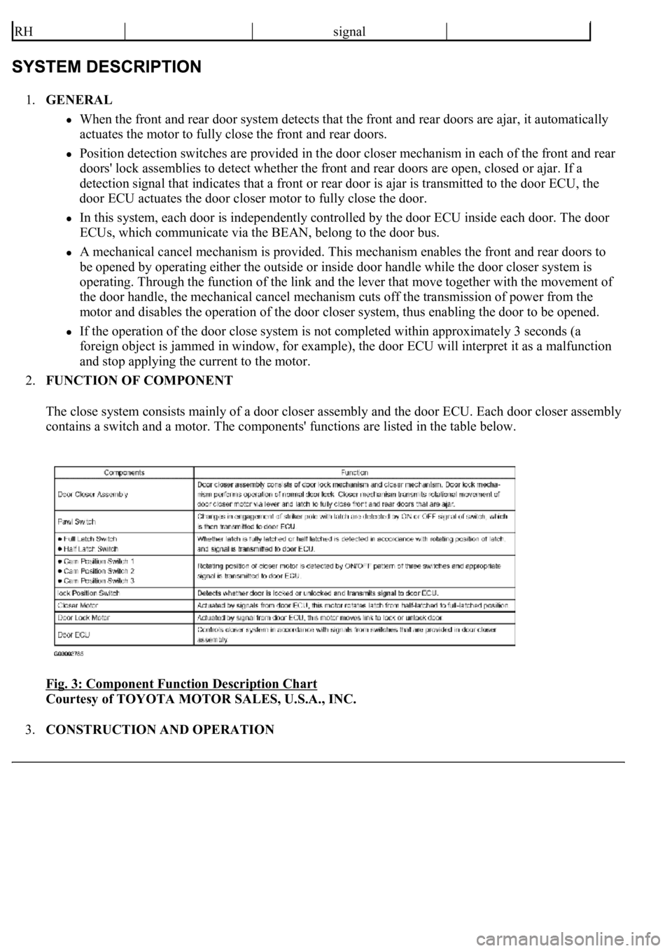
2.FUNCTION OF COMPONENT
The close system consists mainly of a door closer assembly and the door ECU. Each door closer assembly
contains a switch and a motor. The components' functions are listed in the table below.
Fig. 3: Component Function Description Chart
Courtesy of TOYOTA MOTOR SALES, U.S.A., INC.
3.CONSTRUCTION AND OPERATION
RHsignal
Page 2182 of 4500
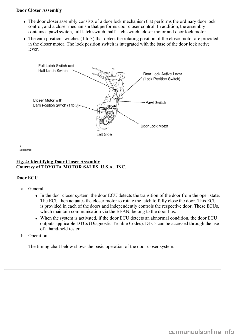
Door Closer Assembly
The door closer assembly consists of a door lock mechanism that performs the ordinary door lock
control, and a closer mechanism that performs door closer control. In addition, the assembly
contains a pawl switch, full latch switch, half latch switch, closer motor and door lock motor.
The cam position switches (1 to 3) that detect the rotating position of the closer motor are provided
<004c005100030057004b004800030046004f0052005600480055000300500052005700520055001100030037004b00480003004f00520046004e0003005300520056004c0057004c0052005100030056005a004c00570046004b0003004c00560003004c00
5100570048004a005500440057004800470003005a004c0057[h the base of the door lock active
lever.
Fig. 4: Identifying Door Closer Assembly
Courtesy of TOYOTA MOTOR SALES, U.S.A., INC.
Door ECU
a. General
In the door closer system, the door ECU detects the transition of the door from the open state.
The ECU then actuates the closer motor to rotate the latch to fully close the door. This ECU
is provided in each of the doors and independently controls the respective door. These ECUs,
which maintain communication via the BEAN, belong to the door bus.
When the system is activated, if the door ECU detects an abnormal condition, the door ECU
outputs applicable DTCs (Diagnostic Trouble Codes). DTCs can be accessed through the use
of a hand-held tester.
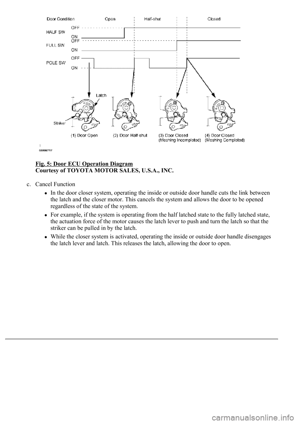
b. Operation
The timin
g chart below shows the basic operation of the door closer system.
Page 2183 of 4500
Fig. 5: Door ECU Operation Diagram
Courtesy of TOYOTA MOTOR SALES, U.S.A., INC.
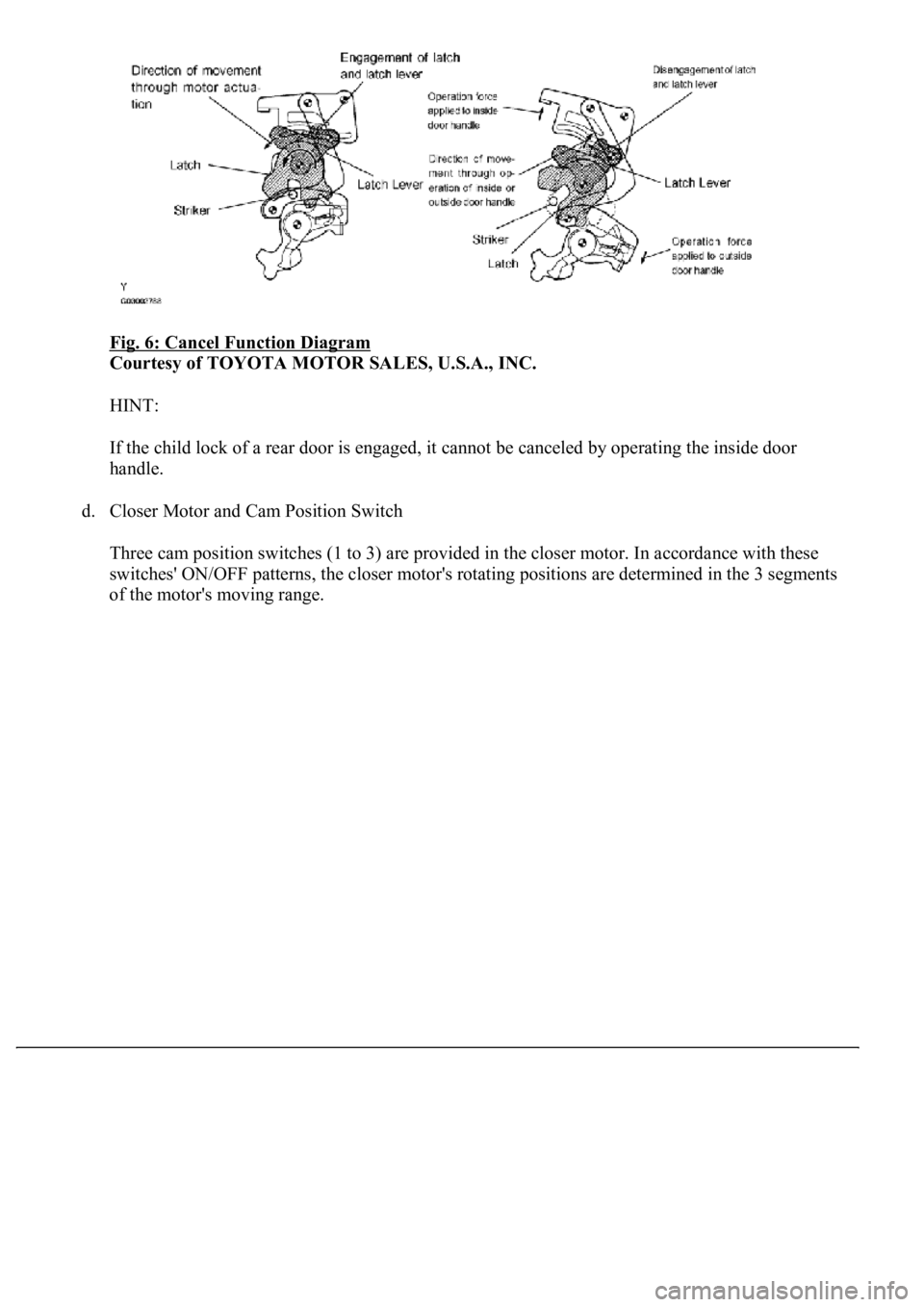
c. Cancel Function
In the door closer system, operating the inside or outside door handle cuts the link between
the latch and the closer motor. This cancels the system and allows the door to be opened
regardless of the state of the system.
For example, if the system is operating from the half latched state to the fully latched state,
the actuation force of the motor causes the latch lever to push and turn the latch so that the
striker can be pulled in by the latch.
While the closer system is activated, operating the inside or outside door handle disengages
the latch lever and latch. This releases the latch, allowing the door to open.
Page 2184 of 4500
Fig. 6: Cancel Function Diagram
Courtesy of TOYOTA MOTOR SALES, U.S.A., INC.
HINT:
If the child lock of a rear door is engaged, it cannot be canceled by operating the inside door
handle.
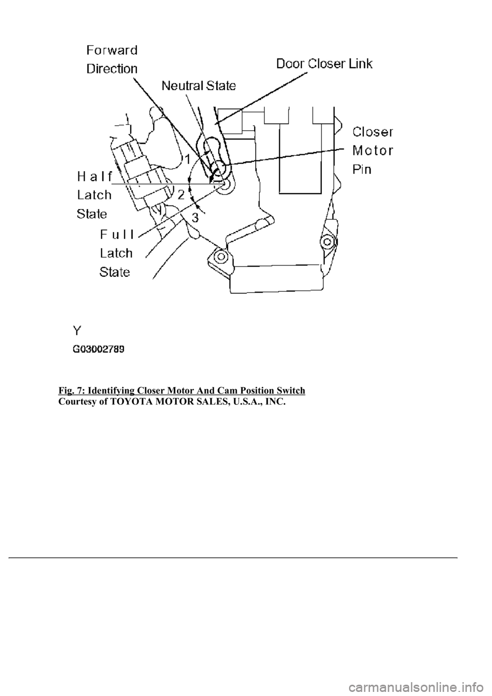
d. Closer Motor and Cam Position Switch
Three cam position switches (1 to 3) are provided in the closer motor. In accordance with these
switches' ON/OFF patterns, the closer motor's rotating positions are determined in the 3 segments
of the motor's movin
g range.
Page 2185 of 4500
Fig. 7: Identifying Closer Motor And Cam Position Switch
Courtesy of TOYOTA MOTOR SALES, U.S.A., INC.
Page 2186 of 4500
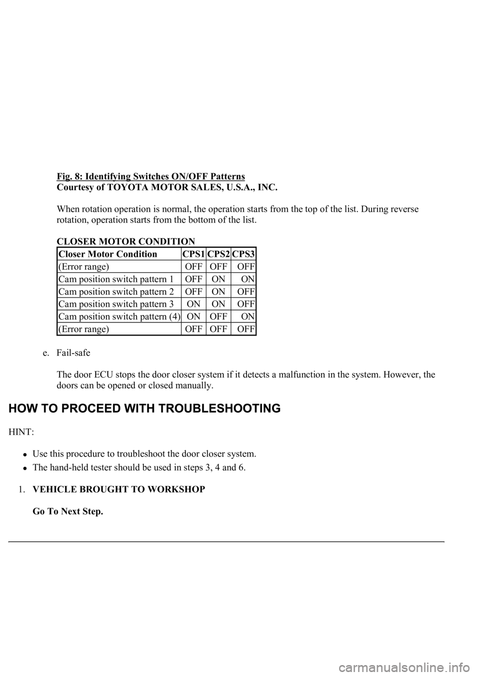
Fig. 8: Identifying Switches ON/OFF Patterns
Courtesy of TOYOTA MOTOR SALES, U.S.A., INC.
When rotation operation is normal, the operation starts from the top of the list. During reverse
rotation, operation starts from the bottom of the list.
CLOSER MOTOR CONDITION
e. Fail-safe
The door ECU stops the door closer system if it detects a malfunction in the system. However, the
doors can be opened or closed manually.
HINT:
Use this procedure to troubleshoot the door closer system.
The hand-held tester should be used in steps 3, 4 and 6.
1.VEHICLE BROUGHT TO WORKSHOP
Go To Next Step.
Closer Motor ConditionCPS1CPS2CPS3
(Error range)OFFOFFOFF
Cam position switch pattern 1OFFONON
Cam position switch pattern 2OFFONOFF
Cam position switch pattern 3ONONOFF
Cam position switch pattern (4)ONOFFON
(Error range)OFFOFFOFF
Page 2187 of 4500
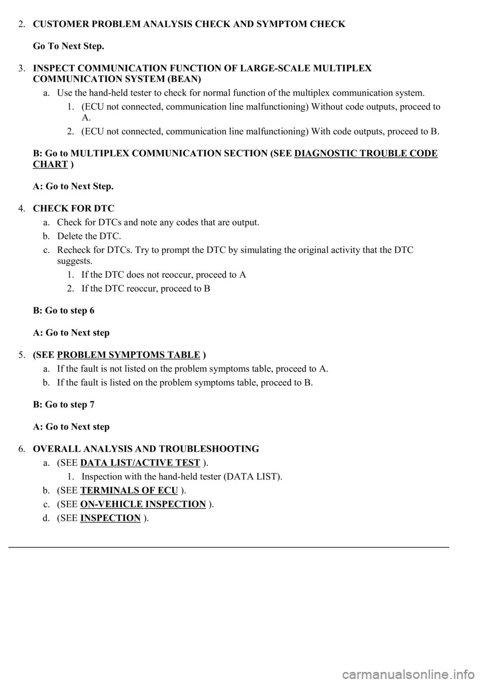
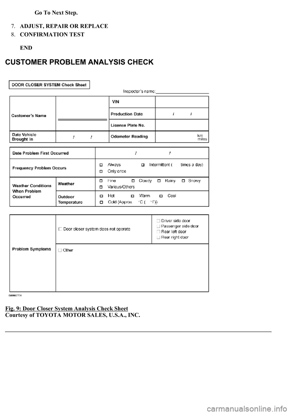
2.CUSTOMER PROBLEM ANALYSIS CHECK AND SYMPTOM CHECK
Go To Next Step.
3.INSPECT COMMUNICATION FUNCTION OF LARGE-SCALE MULTIPLEX
COMMUNICATION SYSTEM (BEAN)
a. Use the hand-held tester to check for normal function of the multiplex communication system.
1. (ECU not connected, communication line malfunctioning) Without code outputs, proceed to
A.
2. (ECU not connected, communication line malfunctioning) With code outputs, proceed to B.
B: Go to MULTIPLEX COMMUNICATION SECTION (SEE DIAGNOSTIC TROUBLE CODE
CHART )
A: Go to Next Step.
4.CHECK FOR DTC
a. Check for DTCs and note any codes that are output.
b. Delete the DTC.
c. Recheck for DTCs. Try to prompt the DTC by simulating the original activity that the DTC
suggests.
1. If the DTC does not reoccur, proceed to A
2. If the DTC reoccur, proceed to B
B: Go to step 6
A: Go to Next step
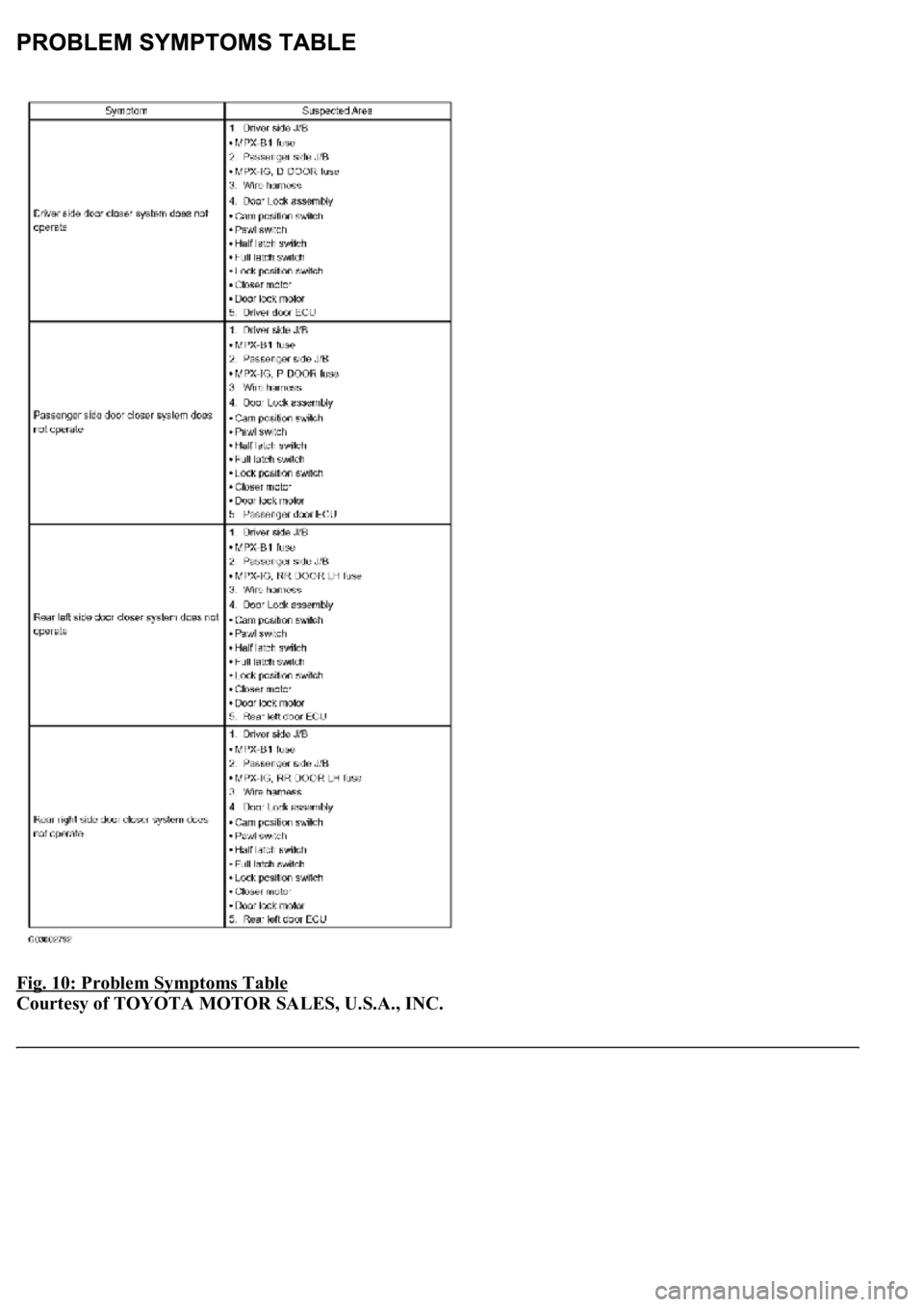
5.(SEE PROBLEM SYMPTOMS TABLE
)
a. If the fault is not listed on the problem symptoms table, proceed to A.
b. If the fault is listed on the problem symptoms table, proceed to B.
B: Go to step 7
A: Go to Next step
6.OVERALL ANALYSIS AND TROUBLESHOOTING
a. (SEE DATA LIST/ACTIVE TEST
).
1. Inspection with the hand-held tester (DATA LIST).
b. (SEE TERMINALS OF ECU
).
c. (SEE ON
-VEHICLE INSPECTION ).
d. (SEE INSPECTION
).
Page 2188 of 4500
Go To Next Step.
7.ADJUST, REPAIR OR REPLACE
8.CONFIRMATION TEST
END
Fig. 9: Door Closer System Analysis Check Sheet
Courtesy of TOYOTA MOTOR SALES, U.S.A., INC.
Page 2189 of 4500
Fig. 10: Problem Symptoms Table
Courtesy of TOYOTA MOTOR SALES, U.S.A., INC.
Page 2190 of 4500
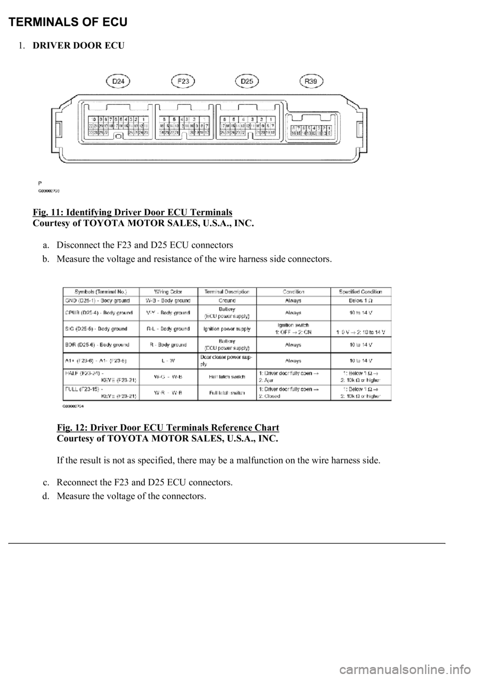
1.DRIVER DOOR ECU
Fig. 11: Identifying Driver Door ECU Terminals
Courtesy of TOYOTA MOTOR SALES, U.S.A., INC.
a. Disconnect the F23 and D25 ECU connectors
b. Measure the voltage and resistance of the wire harness side connectors.
Fig. 12: Driver Door ECU Terminals Reference Chart
Courtesy of TOYOTA MOTOR SALES, U.S.A., INC.
If the result is not as specified, there may be a malfunction on the wire harness side.
c. Reconnect the F23 and D25 ECU connectors.
d. Measure the volta
ge of the connectors.
Trending: lights, ECO mode, drain bolt, fuel filter, evaporator, charging, actuator


