LEXUS LS430 2003 Factory Repair Manual
Manufacturer: LEXUS, Model Year: 2003,
Model line: LS430,
Model: LEXUS LS430 2003
Pages: 4500, PDF Size: 87.45 MB
LEXUS LS430 2003 Factory Repair Manual
LS430 2003
LEXUS
LEXUS
https://www.carmanualsonline.info/img/36/57050/w960_57050-0.png
LEXUS LS430 2003 Factory Repair Manual
Trending: tire pressure, water pump, oil level, ECO mode, fuel pressure, CD player, window regulator
Page 2211 of 4500
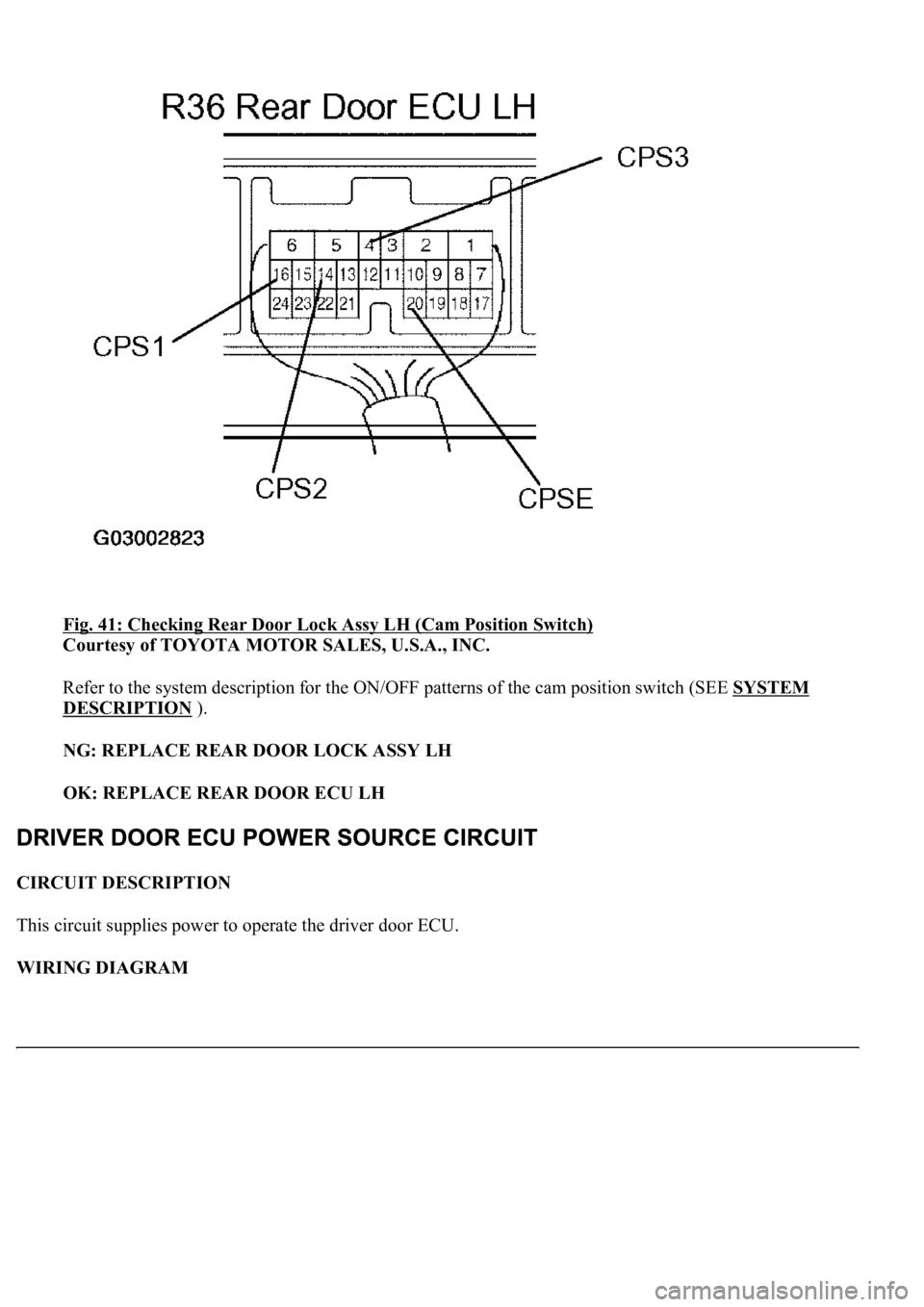
Fig. 41: Checking Rear Door Lock Assy LH (Cam Position Switch)
Courtesy of TOYOTA MOTOR SALES, U.S.A., INC.
Refer to the system description for the ON/OFF patterns of the cam position switch (SEE SYSTEM
DESCRIPTION ).
NG: REPLACE REAR DOOR LOCK ASSY LH
OK: REPLACE REAR DOOR ECU LH
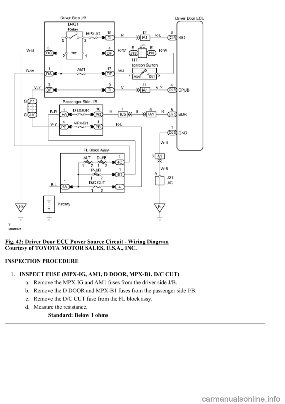
CIRCUIT DESCRIPTION
This circuit supplies power to operate the driver door ECU.
WIRING DIAGRAM
Page 2212 of 4500
Fig. 42: Driver Door ECU Power Source Circuit - Wiring Diagram
Courtesy of TOYOTA MOTOR SALES, U.S.A., INC.
INSPECTION PROCEDURE
1.INSPECT FUSE (MPX-IG, AM1, D DOOR, MPX-B1, D/C CUT)
a. Remove the MPX-IG and AM1 fuses from the driver side J/B.
b. Remove the D DOOR and MPX-B1 fuses from the passenger side J/B.
c. Remove the D/C CUT fuse from the FL block assy.
d. Measure the resistance.
Standard: Below 1 ohms
Page 2213 of 4500
NG: REPLACE FUSE
OK: Go to Next Step.
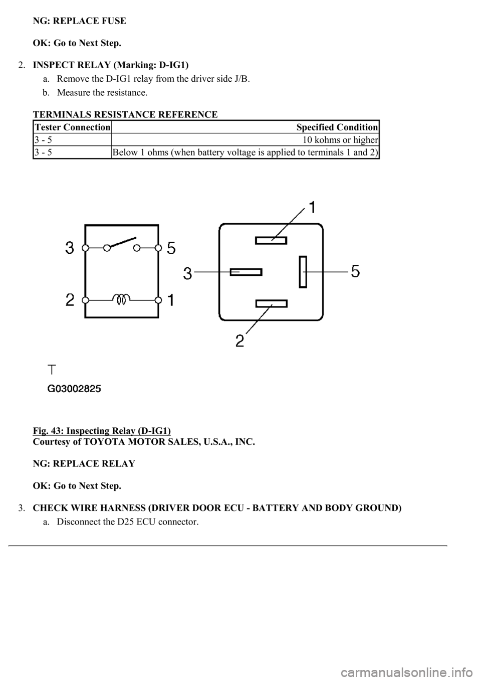
2.INSPECT RELAY (Marking: D-IG1)
a. Remove the D-IG1 relay from the driver side J/B.
b. Measure the resistance.
TERMINALS RESISTANCE REFERENCE
Fig. 43: Inspecting Relay (D
-IG1)
Courtesy of TOYOTA MOTOR SALES, U.S.A., INC.
NG: REPLACE RELAY
OK: Go to Next Step.
3.CHECK WIRE HARNESS (DRIVER DOOR ECU - BATTERY AND BODY GROUND)
a. Disconnect the D25 ECU connector.
Tester ConnectionSpecified Condition
3 - 510 kohms or higher
3 - 5Below 1 ohms (when battery voltage is applied to terminals 1 and 2)
Page 2214 of 4500
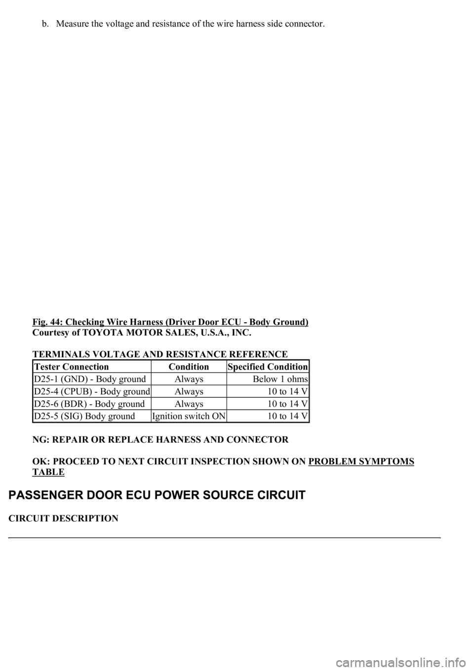
b. Measure the voltage and resistance of the wire harness side connector.
Fig. 44: Checking Wire Harness (Driver Door ECU
- Body Ground)
Courtesy of TOYOTA MOTOR SALES, U.S.A., INC.
TERMINALS VOLTAGE AND RESISTANCE REFERENCE
NG: REPAIR OR REPLACE HARNESS AND CONNECTOR
OK: PROCEED TO NEXT CIRCUIT INSPECTION SHOWN ON PROBLEM SYMPTOMS
TABLE
CIRCUIT DESCRIPTION
Tester ConnectionConditionSpecified Condition
D25-1 (GND) - Body groundAlwaysBelow 1 ohms
D25-4 (CPUB) - Body groundAlways10 to 14 V
D25-6 (BDR) - Body groundAlways10 to 14 V
D25-5 (SIG) Body groundIgnition switch ON10 to 14 V
Page 2215 of 4500
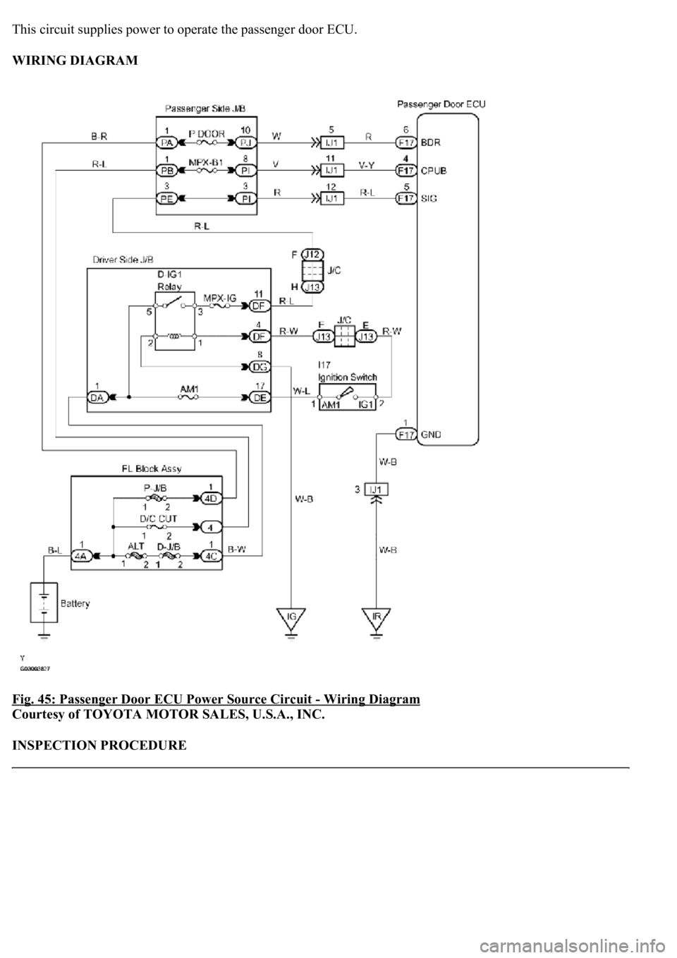
This circuit supplies power to operate the passenger door ECU.
WIRING DIAGRAM
Fig. 45: Passenger Door ECU Power Source Circuit
- Wiring Diagram
Courtesy of TOYOTA MOTOR SALES, U.S.A., INC.
INSPECTION PROCEDURE
Page 2216 of 4500
1.INSPECT FUSE (MPX-IG, AM1, P DOOR, MPX-B1, D/C CUT)
a. Remove the MPX-IG and AM1 fuses from the driver side J/B.
b. Remove the P DOOR and MPX-B1 fuses from the passenger side J/B.
c. Remove the D/C CUT fuse from the FL block assy.
d. Measure the resistance.
Standard: Below 1 ohms
NG: REPLACE FUSE
OK: Go to Next Step.
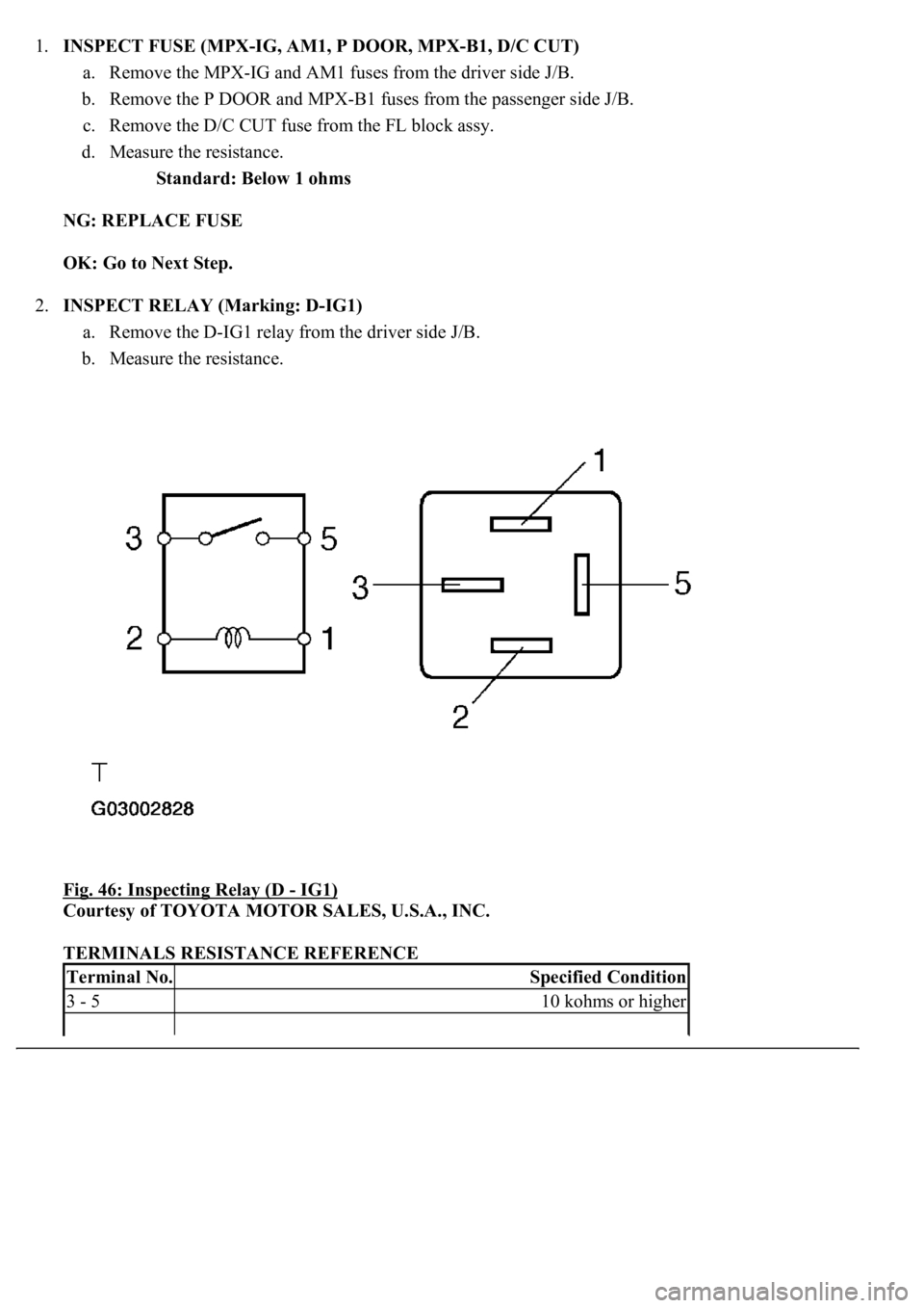
2.INSPECT RELAY (Marking: D-IG1)
a. Remove the D-IG1 relay from the driver side J/B.
b. Measure the resistance.
Fig. 46: Inspecting Relay (D
- IG1)
Courtesy of TOYOTA MOTOR SALES, U.S.A., INC.
TERMINALS RESISTANCE REFERENCE
Terminal No.Specified Condition
3 - 510 kohms or higher
Page 2217 of 4500
NG: REPLACE RELAY
OK: Go to Next Step.
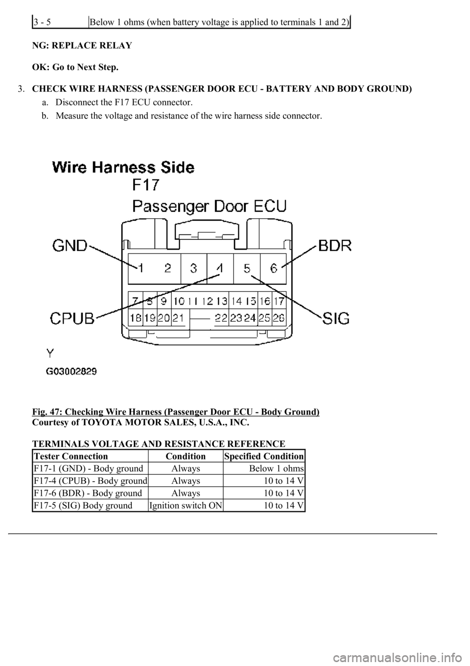
3.CHECK WIRE HARNESS (PASSENGER DOOR ECU - BATTERY AND BODY GROUND)
a. Disconnect the F17 ECU connector.
b. Measure the voltage and resistance of the wire harness side connector.
<0029004c004a001100030017001a001d00030026004b00480046004e004c0051004a0003003a004c005500480003002b0044005500510048005600560003000b003300440056005600480051004a0048005500030027005200520055000300280026003800
03[
- Body Ground)
Courtesy of TOYOTA MOTOR SALES, U.S.A., INC.
TERMINALS VOLTAGE AND RESISTANCE REFERENCE
3 - 5Below 1 ohms (when battery voltage is applied to terminals 1 and 2)
Tester ConnectionConditionSpecified Condition
F17-1 (GND) - Body groundAlwaysBelow 1 ohms
F17-4 (CPUB) - Body groundAlways10 to 14 V
F17-6 (BDR) - Body groundAlways10 to 14 V
F17-5 (SIG) Body groundIgnition switch ON10 to 14 V
Page 2218 of 4500
NG: REPAIR OR REPLACE HARNESS AND CONNECTOR
OK: PROCEED TO NEXT CIRCUIT INSPECTION SHOWN ON PROBLEM SYMPTOMS
TABLE
CIRCUIT DESCRIPTION
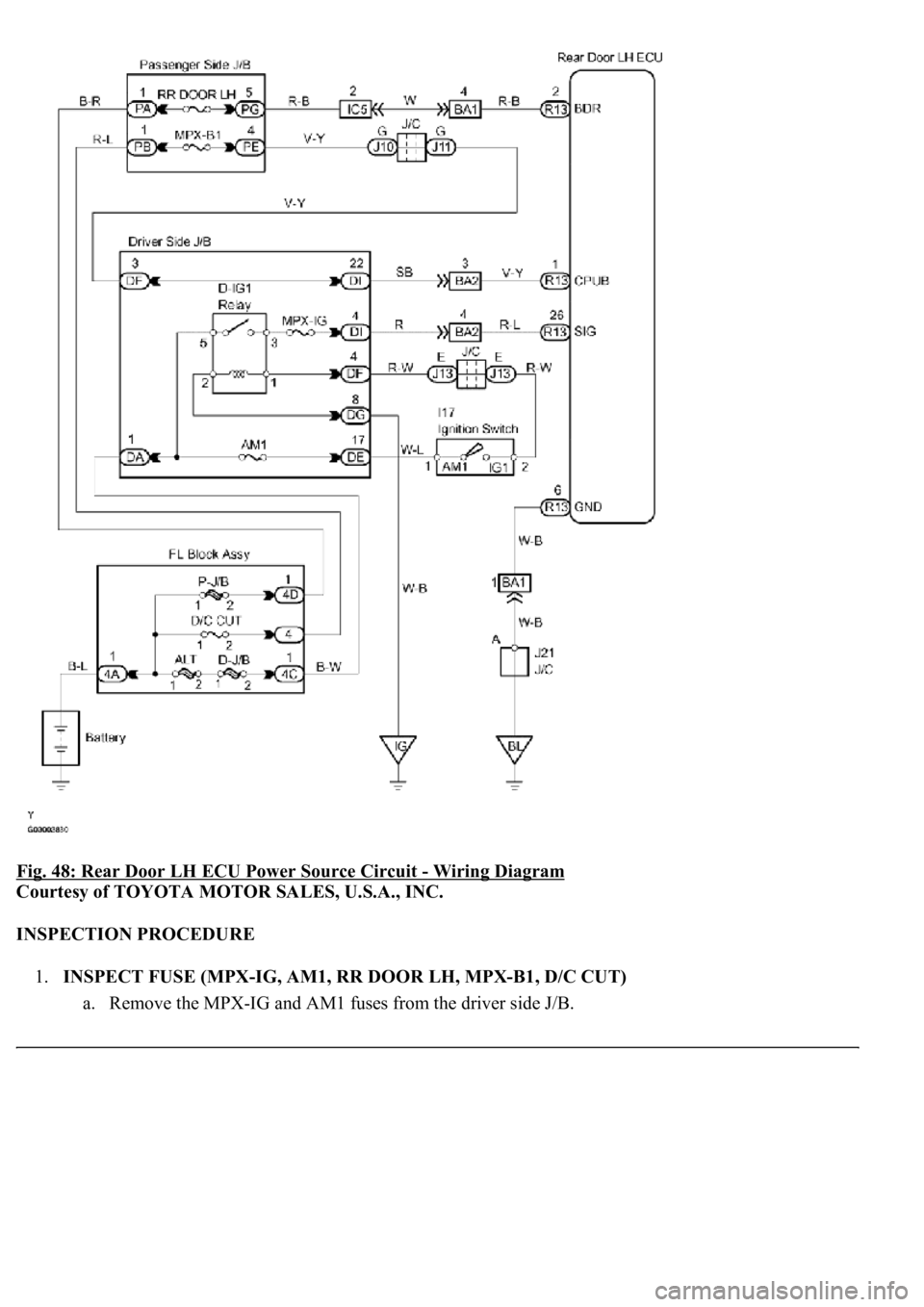
This circuit supplies power to operate the rear door LH ECU.
WIRING DIAGRAM
Page 2219 of 4500
Fig. 48: Rear Door LH ECU Power Source Circuit - Wiring Diagram
Courtesy of TOYOTA MOTOR SALES, U.S.A., INC.
INSPECTION PROCEDURE
1.INSPECT FUSE (MPX-IG, AM1, RR DOOR LH, MPX-B1, D/C CUT)
a. Remove the MPX-IG and AM1 fuses from the driver side J/B.
Page 2220 of 4500
b. Remove the RR DOOR LH and MPX-B1 fuses from the passenger side J/B.
c. Remove the D/C CUT fuse from the FL block assy.
d. Measure the resistance.
Standard: Below 1 ohms
NG: REPLACE FUSE
OK: Go to Next Step.
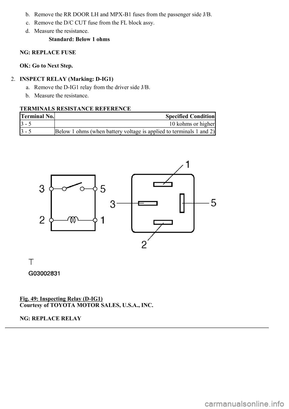
2.INSPECT RELAY (Marking: D-IG1)
a. Remove the D-IG1 relay from the driver side J/B.
b. Measure the resistance.
TERMINALS RESISTANCE REFERENCE
Fig. 49: Inspecting Relay (D
-IG1)
Courtesy of TOYOTA MOTOR SALES, U.S.A., INC.
NG: REPLACE RELAY
Terminal No.Specified Condition
3 - 510 kohms or higher
3 - 5Below 1 ohms (when battery voltage is applied to terminals 1 and 2)
Trending: steering wheel adjustment, Rear control Arm, compressor pressure, sensor, brake, snow chains, fuel filter
