LEXUS LS430 2003 Factory Manual Online
LS430 2003
LEXUS
LEXUS
https://www.carmanualsonline.info/img/36/57050/w960_57050-0.png
LEXUS LS430 2003 Factory Manual Online
Page 3456 of 4500
Fig. 175: Aligning Timing Marks
Courtesy of TOYOTA MOTOR SALES, U.S.A., INC.
74.INSTALL CRANKSHAFT POSITION SENSOR PLATE NO.1
a. Install the sensor plate. Face the cup side outward.
75.INSTALL TIMING GEAR COVER SPACER
a. Install the gasket to the cover spacer.
b. Install the cover spacer.
76.INSTALL TIMING BELT NO.1 COVER
a. Install the timing belt cover with the 4 bolts.
Torque: 7.5 N.m (77 kgf.cm, 66 in.lbf)
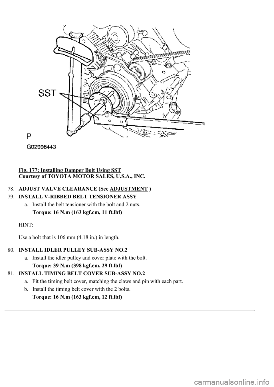
77.INSTALL CRANKSHAFT DAMPER SUB-ASSY
a. Using SST and a hammer, tap in the crankshaft damper.
SST 09223-46011
Page 3458 of 4500
Fig. 177: Installing Damper Bolt Using SST
Courtesy of TOYOTA MOTOR SALES, U.S.A., INC.
78.ADJUST VALVE CLEARANCE (See ADJUSTMENT
)
79.INSTALL V-RIBBED BELT TENSIONER ASSY
a. Install the belt tensioner with the bolt and 2 nuts.
Torque: 16 N.m (163 kgf.cm, 11 ft.lbf)
HINT:
Use a bolt that is 106 mm (4.18 in.) in length.
80.INSTALL IDLER PULLEY SUB-ASSY NO.2
a. Install the idler pulley and cover plate with the bolt.
Torque: 39 N.m (398 kgf.cm, 29 ft.lbf)
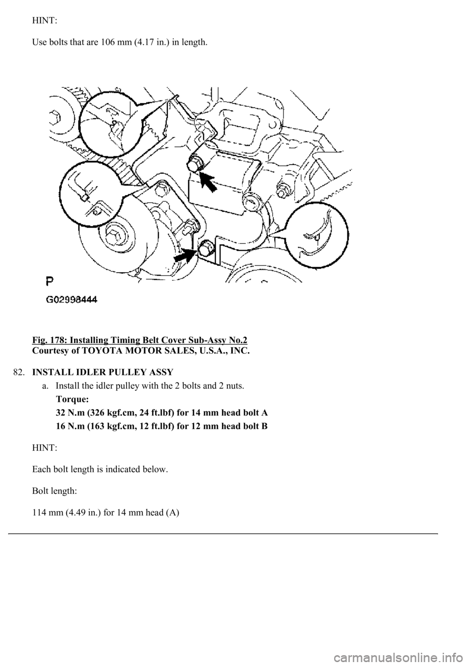
81.INSTALL TIMING BELT COVER SUB-ASSY NO.2
a. Fit the timing belt cover, matching the claws and pin with each part.
b. Install the timing belt cover with the 2 bolts.
Torque: 16 N.m (163 kgf.cm, 12 ft.lbf)
Page 3459 of 4500
HINT:
Use bolts that are 106 mm (4.17 in.) in length.
Fig. 178: Installing Timing Belt Cover Sub
-Assy No.2
Courtesy of TOYOTA MOTOR SALES, U.S.A., INC.
82.INSTALL IDLER PULLEY ASSY
a. Install the idler pulley with the 2 bolts and 2 nuts.
Torque:
32 N.m (326 kgf.cm, 24 ft.lbf) for 14 mm head bolt A
16 N.m (163 kgf.cm, 12 ft.lbf) for 12 mm head bolt B
HINT:
Each bolt length is indicated below.
Bolt length:
114 mm (4.49 in.) for 14 mm head (A)
Page 3460 of 4500
106 mm (4.17 in.) for 12 mm head (B)
Fig. 179: Installing Idler Pulley Assy
Courtesy of TOYOTA MOTOR SALES, U.S.A., INC.
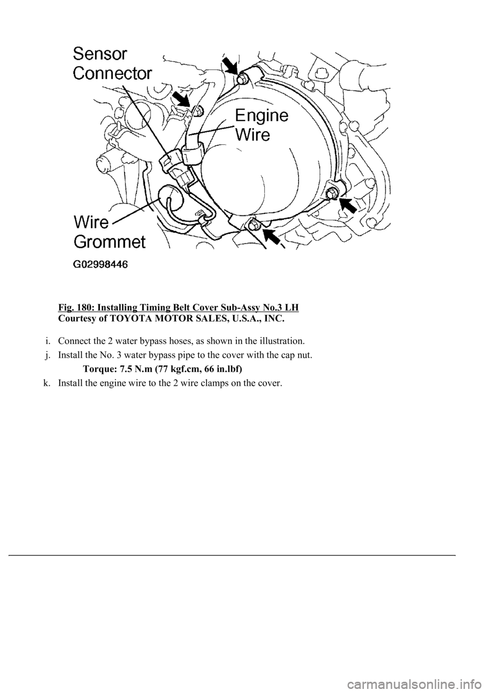
83.INSTALL TIMING BELT COVER SUB-ASSY NO.3 LH
a. Install the gasket to the cover.
b. Run the camshaft position sensor wire through the cover hole.
c. Install the cover with the 4 bolts.
Torque: 7.5 N.m (77 kgf.cm, 66 in.lbf)
d. Install the wire grommet to the cover.
e. Install the sensor connector to the sensor holder.
f. Connect the sensor connector.
g. Install the sensor wire to the wire clamp on the cover.
h. Install the en
gine wire to the 2 wire clamps on the cover.
Page 3461 of 4500
Fig. 180: Installing Timing Belt Cover Sub-Assy No.3 LH
Courtesy of TOYOTA MOTOR SALES, U.S.A., INC.
i. Connect the 2 water bypass hoses, as shown in the illustration.
j. Install the No. 3 water bypass pipe to the cover with the cap nut.
Torque: 7.5 N.m (77 kgf.cm, 66 in.lbf)
k. Install the en
gine wire to the 2 wire clamps on the cover.
Page 3462 of 4500
Fig. 181: Connecting Water By-Pass Hoses
Courtesy of TOYOTA MOTOR SALES, U.S.A., INC.
84.INSTALL TIMING CHAIN OR BELT COVER NO.2
a. Install the gasket to the cover.
b. Install the cover with the cap nut and 3 bolts.
Torque: 7.5 N.m (77 kgf.cm, 66 in.lbf)
c. Install the 2 PS air hoses to the clamp on the cover.
Page 3468 of 4500
Courtesy of TOYOTA MOTOR SALES, U.S.A., INC.
87.INSTALL OIL FILLER CAP SUB-ASSY
88.INSTALL SPARK PLUG
REPLACEMENT
1.DISCONNECT BATTERY NEGATIVE TERMINAL
2.REMOVE AIR CLEANER INLET NO.1
3.DRAIN ENGINE COOLANT
4.REMOVE V-BANK COVER
5.REMOVE INTAKE AIR CONNECTOR PIPE
6.REMOVE ENGINE UNDER COVER NO.1
7.DISCONNECT RADIATOR HOSE NO.1
8.DISCONNECT RADIATOR HOSE NO.2
9.DISCONNECT OIL COOLER INLET TUBE NO.1
10.DISCONNECT OIL COOLER OUTLET TUBE NO.1
11.REMOVE AIR CLEANER ASSY
12.REMOVE RADIATOR ASSY (See REPLACEMENT
13.REMOVE FAN AND GENERATOR V BELT (See REPLACEMENT
)
14.REMOVE VANE PUMP ASSY
a. Remove the 2 bolts, nut and pump.
HINT:
Pump should be removed with the hoses connected and then hang with a rope or wire on the body's side.
15.REMOVE GENERATOR ASSY (See REPLACEMENT
)
16.DISCONNECT COMPRESSOR AND MAGNETIC CLUTCH
HINT:
The cooler compressor with the magnetic clutch should be removed with the low-pressure and high-
pressure hoses connected and then hang with a rope or wire on the body's side.
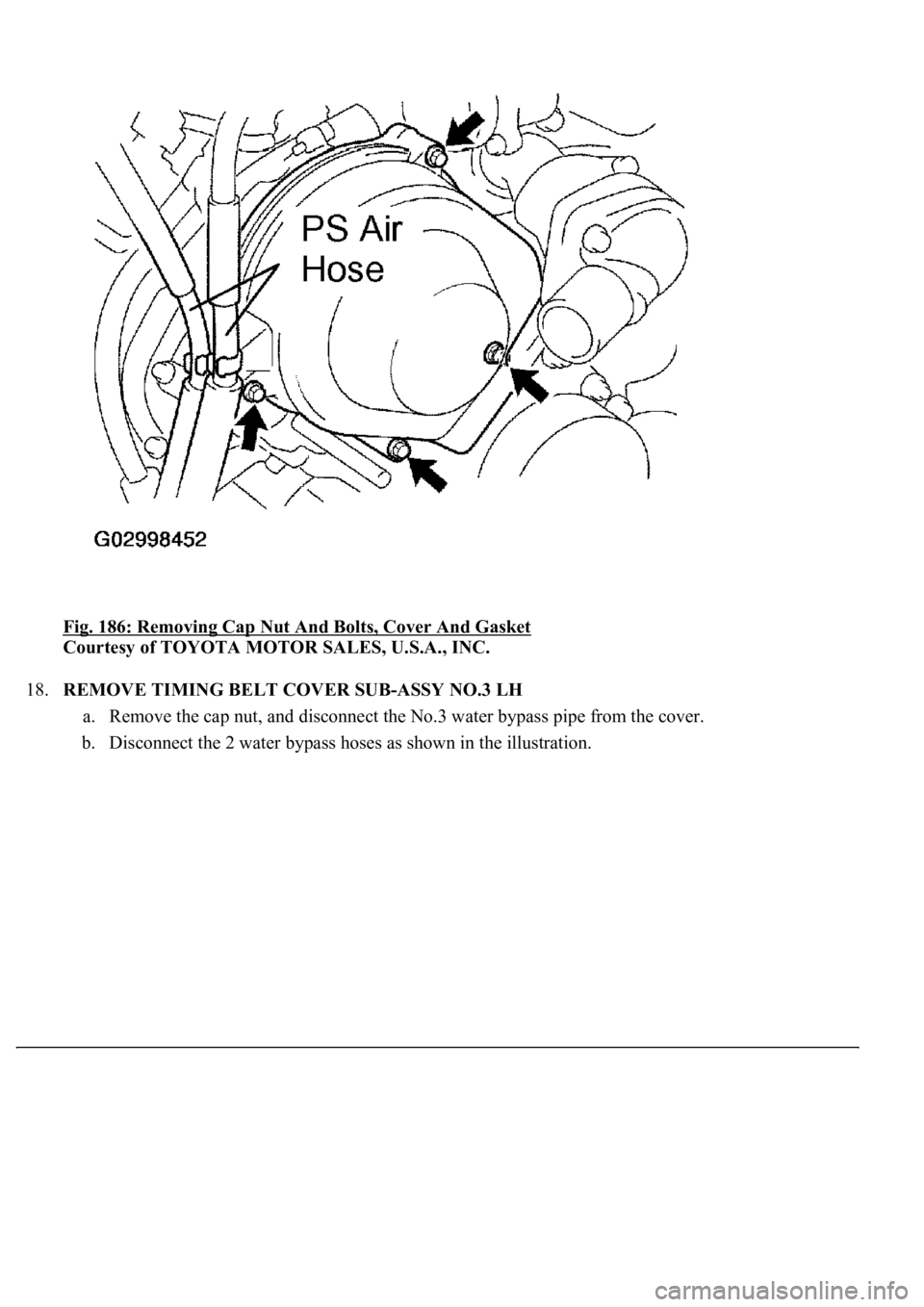
17.REMOVE TIMING CHAIN OR BELT COVER NO.2
a. Disconnect the 2 PS air hoses from the clamp on the cover.
b. Remove the cap nut, 3 bolts, cover and gasket.
Page 3469 of 4500
Fig. 186: Removing Cap Nut And Bolts, Cover And Gasket
Courtesy of TOYOTA MOTOR SALES, U.S.A., INC.
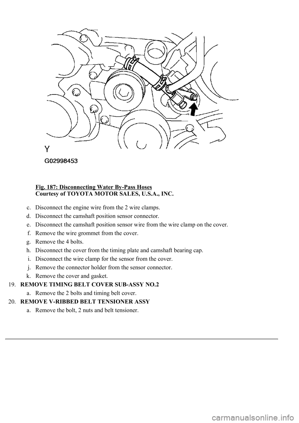
18.REMOVE TIMING BELT COVER SUB-ASSY NO.3 LH
a. Remove the cap nut, and disconnect the No.3 water bypass pipe from the cover.
b. Disconnect the 2 water bypass hoses as shown in the illustration.
Page 3470 of 4500
Fig. 187: Disconnecting Water By-Pass Hoses
Courtesy of TOYOTA MOTOR SALES, U.S.A., INC.
c. Disconnect the engine wire from the 2 wire clamps.
d. Disconnect the camshaft position sensor connector.
e. Disconnect the camshaft position sensor wire from the wire clamp on the cover.
f. Remove the wire grommet from the cover.
g. Remove the 4 bolts.
h. Disconnect the cover from the timing plate and camshaft bearing cap.
i. Disconnect the wire clamp for the sensor from the cover.
j. Remove the connector holder from the sensor connector.
k. Remove the cover and gasket.
19.REMOVE TIMING BELT COVER SUB-ASSY NO.2
a. Remove the 2 bolts and timing belt cover.
20.REMOVE V-RIBBED BELT TENSIONER ASSY
a. Remove the bolt, 2 nuts and belt tensioner.
Page 3473 of 4500
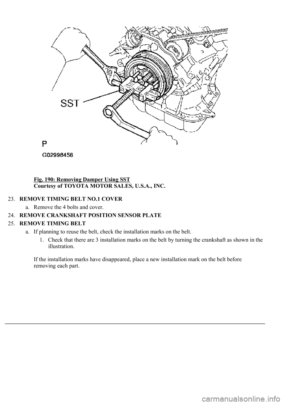
Fig. 190: Removing Damper Using SST
Courtesy of TOYOTA MOTOR SALES, U.S.A., INC.
23.REMOVE TIMING BELT NO.1 COVER
a. Remove the 4 bolts and cover.
24.REMOVE CRANKSHAFT POSITION SENSOR PLATE
25.REMOVE TIMING BELT
a. If planning to reuse the belt, check the installation marks on the belt.
1. Check that there are 3 installation marks on the belt by turning the crankshaft as shown in the
illustration.
If the installation marks have disappeared, place a new installation mark on the belt before
removing each part.