sensor LEXUS LS430 2003 Factory Repair Manual
[x] Cancel search | Manufacturer: LEXUS, Model Year: 2003, Model line: LS430, Model: LEXUS LS430 2003Pages: 4500, PDF Size: 87.45 MB
Page 3198 of 4500
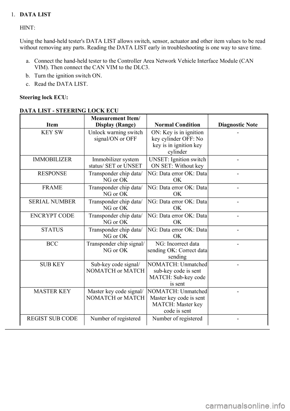
1.DATA LIST
HINT:
Using the hand-held tester's DATA LIST allows switch, sensor, actuator and other item values to be read
without removing any parts. Reading the DATA LIST early in troubleshooting is one way to save time.
a. Connect the hand-held tester to the Controller Area Network Vehicle Interface Module (CAN
VIM). Then connect the CAN VIM to the DLC3.
b. Turn the ignition switch ON.
c. Read the DATA LIST.
Steering lock ECU:
DATA LIST - STEERING LOCK ECU
Item
Measurement Item/
Display (Range)
Normal ConditionDiagnostic Note
KEY SWUnlock warning switch
signal/ON or OFFON: Key is in ignition
key cylinder OFF: No
key is in ignition key
cylinder-
IMMOBILIZERImmobilizer system
status/ SET or UNSETUNSET: Ignition switch
ON SET: Without key-
RESPONSETransponder chip data/
NG or OKNG: Data error OK: Data
OK-
FRAMETransponder chip data/
NG or OKNG: Data error OK: Data
OK-
SERIAL NUMBERTransponder chip data/
NG or OKNG: Data error OK: Data
OK-
ENCRYPT CODETransponder chip data/
NG or OKNG: Data error OK: Data
OK-
STATUSTransponder chip data/
NG or OKNG: Data error OK: Data
OK-
BCCTransponder chip signal/
NG or OKNG: Incorrect data
sending OK: Correct data
sending-
SUB KEYSub-key code signal/
NOMATCH or MATCHNOMATCH: Unmatched
sub-key code is sent
MATCH: Sub-key code
is sent-
MASTER KEYMaster key code signal/
NOMATCH or MATCHNOMATCH: Unmatched
Master key code is sent
MATCH: Master key
code is sent-
REGIST SUB CODENumber of registered Number of registered -
Page 3253 of 4500
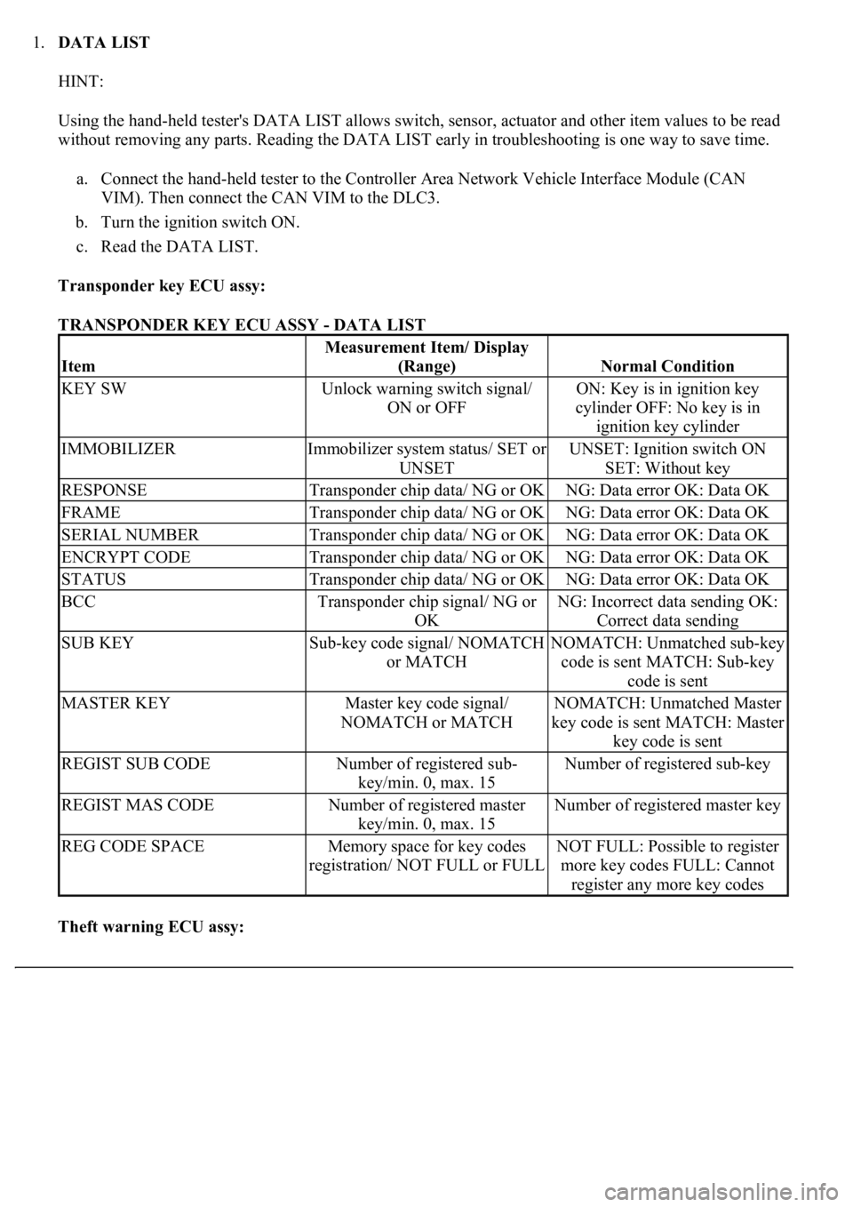
1.DATA LIST
HINT:
Using the hand-held tester's DATA LIST allows switch, sensor, actuator and other item values to be read
without removing any parts. Reading the DATA LIST early in troubleshooting is one way to save time.
a. Connect the hand-held tester to the Controller Area Network Vehicle Interface Module (CAN
VIM). Then connect the CAN VIM to the DLC3.
b. Turn the ignition switch ON.
c. Read the DATA LIST.
Transponder key ECU assy:
TRANSPONDER KEY ECU ASSY - DATA LIST
Theft warning ECU assy:
Item
Measurement Item/ Display
(Range)
Normal Condition
KEY SWUnlock warning switch signal/
ON or OFFON: Key is in ignition key
cylinder OFF: No key is in
ignition key cylinder
IMMOBILIZERImmobilizer system status/ SET or
UNSETUNSET: Ignition switch ON
SET: Without key
RESPONSETransponder chip data/ NG or OKNG: Data error OK: Data OK
FRAMETransponder chip data/ NG or OKNG: Data error OK: Data OK
SERIAL NUMBERTransponder chip data/ NG or OKNG: Data error OK: Data OK
ENCRYPT CODETransponder chip data/ NG or OKNG: Data error OK: Data OK
STATUSTransponder chip data/ NG or OKNG: Data error OK: Data OK
BCCTransponder chip signal/ NG or
OKNG: Incorrect data sending OK:
Correct data sending
SUB KEYSub-key code signal/ NOMATCH
or MATCHNOMATCH: Unmatched sub-key
code is sent MATCH: Sub-key
code is sent
MASTER KEYMaster key code signal/
NOMATCH or MATCHNOMATCH: Unmatched Master
key code is sent MATCH: Master
key code is sent
REGIST SUB CODENumber of registered sub-
key/min. 0, max. 15Number of registered sub-key
REGIST MAS CODENumber of registered master
key/min. 0, max. 15Number of registered master key
REG CODE SPACEMemory space for key codes
registration/ NOT FULL or FULLNOT FULL: Possible to register
more key codes FULL: Cannot
register any more key codes
Page 3286 of 4500
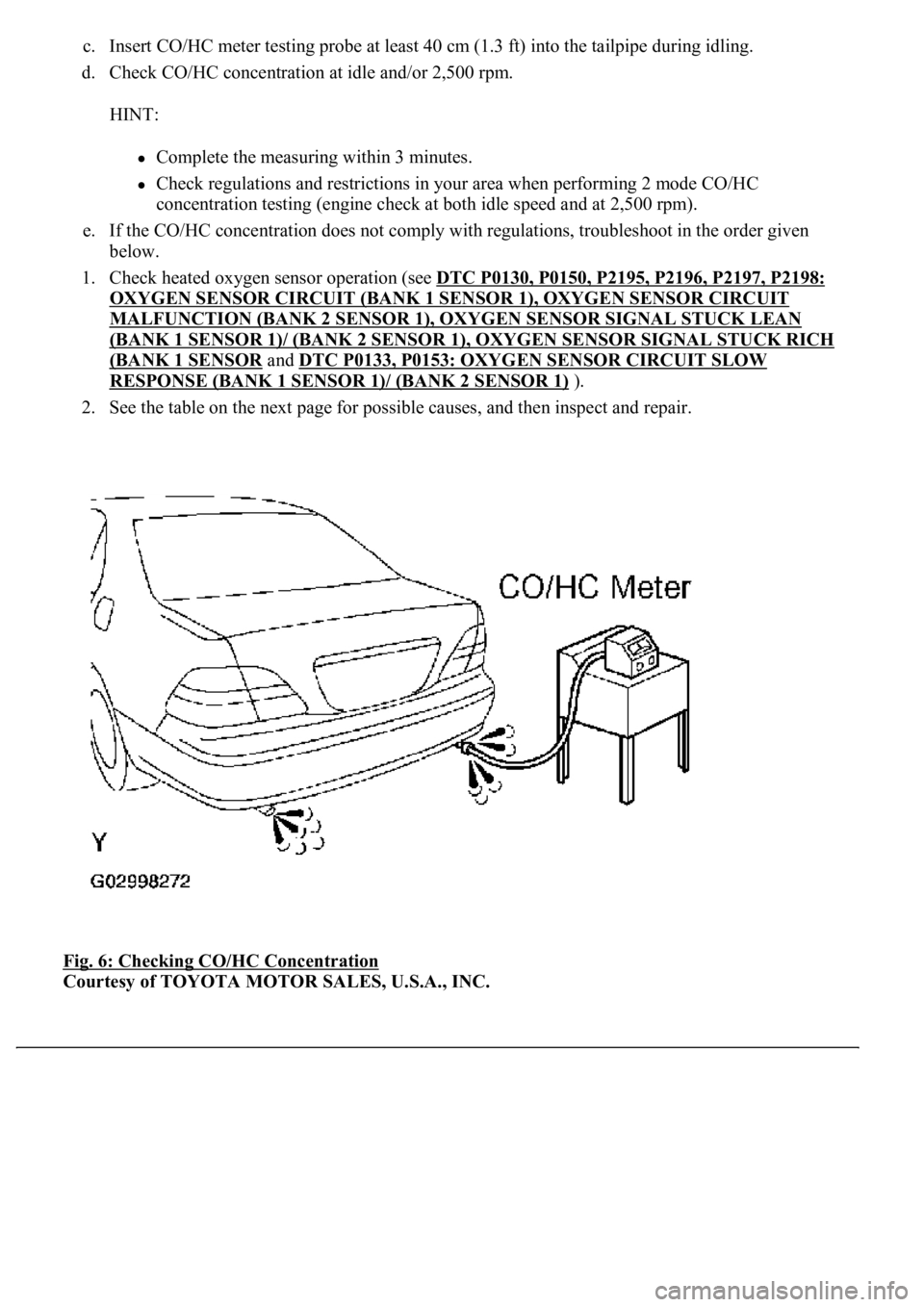
c. Insert CO/HC meter testing probe at least 40 cm (1.3 ft) into the tailpipe during idling.
d. Check CO/HC concentration at idle and/or 2,500 rpm.
HINT:
Complete the measuring within 3 minutes.
Check regulations and restrictions in your area when performing 2 mode CO/HC
concentration testing (engine check at both idle speed and at 2,500 rpm).
e. If the CO/HC concentration does not comply with regulations, troubleshoot in the order given
below.
1. Check heated oxygen sensor operation (see DTC P0130, P0150, P2195, P2196, P2197, P2198:
OXYGEN SENSOR CIRCUIT (BANK 1 SENSOR 1), OXYGEN SENSOR CIRCUIT
MALFUNCTION (BANK 2 SENSOR 1), OXYGEN SENSOR SIGNAL STUCK LEAN
(BANK 1 SENSOR 1)/ (BANK 2 SENSOR 1), OXYGEN SENSOR SIGNAL STUCK RICH
(BANK 1 SENSOR and DTC P0133, P0153: OXYGEN SENSOR CIRCUIT SLOW
RESPONSE (BANK 1 SENSOR 1)/ (BANK 2 SENSOR 1) ).
2. See the table on the next page for possible causes, and then inspect and repair.
Fig. 6: Checking CO/HC Concentration
Courtesy of TOYOTA MOTOR SALES, U.S.A., INC.
Page 3314 of 4500
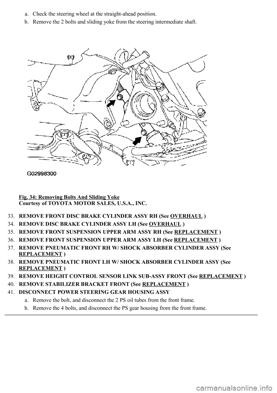
a. Check the steering wheel at the straight-ahead position.
b. Remove the 2 bolts and sliding yoke from the steering intermediate shaft.
Fig. 34: Removing Bolts And Sliding Yoke
Courtesy of TOYOTA MOTOR SALES, U.S.A., INC.
33.REMOVE FRONT DISC BRAKE CYLINDER ASSY RH (See OVERHAUL
)
34.REMOVE DISC BRAKE CYLINDER ASSY LH (See OVERHAUL
)
35.REMOVE FRONT SUSPENSION UPPER ARM ASSY RH (See REPLACEMENT
)
36.REMOVE FRONT SUSPENSION UPPER ARM ASSY LH (See REPLACEMENT
)
37.REMOVE PNEUMATIC FRONT RH W/ SHOCK ABSORBER CYLINDER ASSY (See
REPLACEMENT
)
38.REMOVE PNEUMATIC FRONT LH W/ SHOCK ABSORBER CYLINDER ASSY (See
REPLACEMENT
)
39.REMOVE HEIGHT CONTROL SENSOR LINK SUB-ASSY FRONT (See REPLACEMENT
)
40.REMOVE STABILIZER BRACKET FRONT (See REPLACEMENT
)
41.DISCONNECT POWER STEERING GEAR HOUSING ASSY
a. Remove the bolt, and disconnect the 2 PS oil tubes from the front frame.
b. Remove the 4 bolts, and disconnect the PS gear housing from the front frame.
Page 3318 of 4500
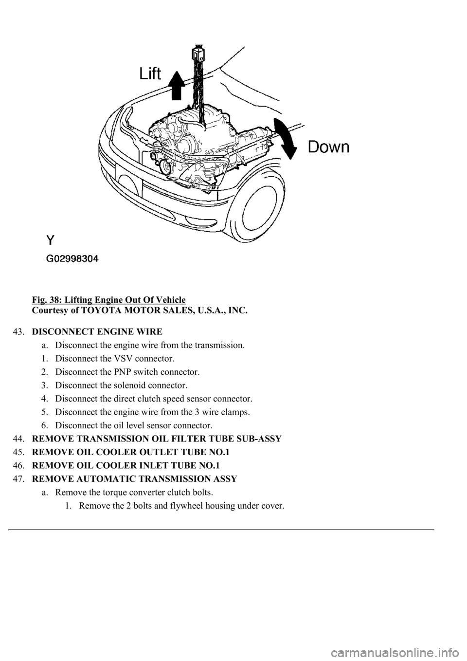
Fig. 38: Lifting Engine Out Of Vehicle
Courtesy of TOYOTA MOTOR SALES, U.S.A., INC.
43.DISCONNECT ENGINE WIRE
a. Disconnect the engine wire from the transmission.
1. Disconnect the VSV connector.
2. Disconnect the PNP switch connector.
3. Disconnect the solenoid connector.
4. Disconnect the direct clutch speed sensor connector.
5. Disconnect the engine wire from the 3 wire clamps.
6. Disconnect the oil level sensor connector.
44.REMOVE TRANSMISSION OIL FILTER TUBE SUB-ASSY
45.REMOVE OIL COOLER OUTLET TUBE NO.1
46.REMOVE OIL COOLER INLET TUBE NO.1
47.REMOVE AUTOMATIC TRANSMISSION ASSY
a. Remove the torque converter clutch bolts.
1. Remove the 2 bolts and fl
ywheel housing under cover.
Page 3326 of 4500
54.REMOVE GENERATOR ASSY (See REPLACEMENT )
55.REMOVE WATER INLET HOUSING
a. Remove the 2 bolts and inlet housing.
56.REMOVE WATER BYPASS JOINT FR
a. Disconnect the ECT sensor connector.
b. Remove the 4 nuts, water bypass joint and 2 gaskets.
Fig. 46: Identifying Water By
-Pass Joint FR
Courtesy of TOYOTA MOTOR SALES, U.S.A., INC.
57.REMOVE WATER BYPASS JOINT RR
a. Disconnect the heater inlet hose from the water bypass joint.
b. Remove the 4 nuts, water bypass joint and 2 gaskets.
Page 3327 of 4500
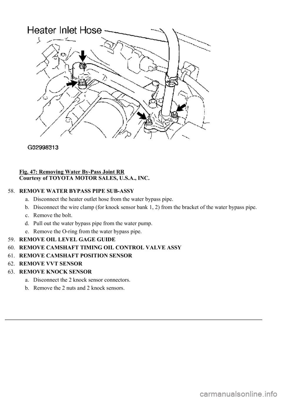
Fig. 47: Removing Water By-Pass Joint RR
Courtesy of TOYOTA MOTOR SALES, U.S.A., INC.
58.REMOVE WATER BYPASS PIPE SUB-ASSY
a. Disconnect the heater outlet hose from the water bypass pipe.
b. Disconnect the wire clamp (for knock sensor bank 1, 2) from the bracket of the water bypass pipe.
c. Remove the bolt.
d. Pull out the water bypass pipe from the water pump.
e. Remove the O-ring from the water bypass pipe.
59.REMOVE OIL LEVEL GAGE GUIDE
60.REMOVE CAMSHAFT TIMING OIL CONTROL VALVE ASSY
61.REMOVE CAMSHAFT POSITION SENSOR
62.REMOVE VVT SENSOR
63.REMOVE KNOCK SENSOR
a. Disconnect the 2 knock sensor connectors.
b. Remove the 2 nuts and 2 knock sensors.
Page 3328 of 4500
Fig. 48: Identifying Knock Sensor Connectors
Courtesy of TOYOTA MOTOR SALES, U.S.A., INC.
64.REMOVE ENGINE HANGER NO.1
65.REMOVE ENGINE HANGER NO.2
66.REMOVE IGNITION COIL ASSY
67.REMOVE OIL FILTER BRACKET SUB-ASSY
a. Disconnect the oil pressure switch connector.
b. Remove the stud bolt, 2 nuts and oil filter bracket with gasket.
68.REMOVE CRANKSHAFT POSITION SENSOR
69.REMOVE ENGINE OIL LEVEL SENSOR
70.REMOVE EXHAUST MANIFOLD HEAT INSULATOR NO.1
71.REMOVE EXHAUST MANIFOLD SUB-ASSY RH
a. Remove the 8 nuts, exhaust manifold and
gasket.
Page 3338 of 4500
Fig. 58: Installing Exhaust Manifold
Courtesy of TOYOTA MOTOR SALES, U.S.A., INC.
85.INSTALL EXHAUST MANIFOLD HEAT INSULATOR NO.1
86.INSTALL ENGINE OIL LEVEL SENSOR
87.INSTALL CRANKSHAFT POSITION SENSOR (See REPLACEMENT
)
88.INSTALL OIL FILTER BRACKET SUB-ASSY
Torque: 18 N.m (184 kgf.cm, 13 ft.lbf)
89.INSTALL IGNITION COIL ASSY
Torque: 7.5 N.m (77 kgf.cm, 66 in.lbf)
90.INSTALL ENGINE HANGER NO.2
Torque: 37 N.m (377 kgf.cm, 27 ft.lbf)
91.INSTALL ENGINE HANGER NO. 1
Torque: 37 N.m (377 kgf.cm, 27 ft.lbf)
92.INSTALL KNOCK SENSOR
a. Install the 2 knock sensors with the 2 nuts, as shown in the illustration.
Torque: 20 N.m (204 kgf.cm, 15 ft.lbf)
b. Connect the 2 knock sensor connectors.
Page 3339 of 4500
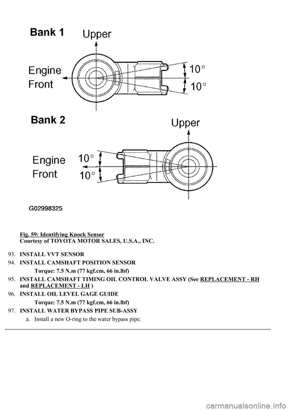
Fig. 59: Identifying Knock Sensor
Courtesy of TOYOTA MOTOR SALES, U.S.A., INC.
93.INSTALL VVT SENSOR
94.INSTALL CAMSHAFT POSITION SENSOR
Torque: 7.5 N.m (77 kgf.cm, 66 in.lbf)
95.INSTALL CAMSHAFT TIMING OIL CONTROL VALVE ASSY (See REPLACEMENT
- RH
and REPLACEMENT
- LH )
96.INSTALL OIL LEVEL GAGE GUIDE
Torque: 7.5 N.m (77 kgf.cm, 66 in.lbf)
97.INSTALL WATER BYPASS PIPE SUB-ASSY
a. Install a new O-rin
g to the water bypass pipe.