service LINCOLN MKZ 2013 Workshop Manual
[x] Cancel search | Manufacturer: LINCOLN, Model Year: 2013, Model line: MKZ, Model: LINCOLN MKZ 2013Pages: 474, PDF Size: 3.79 MB
Page 274 of 474
What you Should Know About
Fail-Safe Cooling
If the engine coolant supply is
depleted, this feature allows the
vehicle to be driven temporarily before
incremental component damage is
incurred. The
“fail-safe” distance
depends on ambient temperatures,
vehicle load and terrain.
How Fail-Safe Cooling Works
If the engine begins to overheat, the
engine coolant temperature gauge
will move to the red (hot) area and: The coolant temperature
warning light will illuminate.
The service engine soon
indicator will illuminate.
If the engine reaches a preset
over-temperature condition, the
engine will automatically switch to
alternating cylinder operation. Each
disabled cylinder acts as an air pump
and cools the engine.
When this occurs the vehicle will still
operate. However:
• The engine power will be limited.
• The air conditioning system will be
disabled.
Continued operation will increase the
engine temperature and the engine
will completely shut down, causing
steering and braking effort to increase. Once the engine temperature cools,
the engine can be re-started. Take
your vehicle to an authorized dealer
as soon as possible to minimize
engine damage.
When Fail-Safe Mode Is Activated WARNINGS
Fail-safe mode is for use during
emergencies only. Operate the
vehicle in fail-safe mode only as long
as necessary to bring the vehicle to
rest in a safe location and seek
immediate repairs. When in fail-safe
mode, the vehicle will have limited
power, will not be able to maintain
high-speed operation, and may
completely shut down without
warning, potentially losing engine
power, power steering assist, and
power brake assist, which may
increase the possibility of a crash
resulting in serious injury. Never remove the coolant
reservoir cap while the engine is
running or hot. You have limited engine power when
in the fail-safe mode, so drive the
vehicle with caution. The vehicle will
not be able to maintain high-speed
operation and the engine will run
rough. Remember that the engine is
capable of completely shutting down
automatically to prevent engine
damage, therefore:
1. Pull off the road as soon as safely
possible and turn off the engine.
2. Arrange for the vehicle to be taken
to an authorized dealer.
271
Maintenance
Page 275 of 474
3. If this is not possible, wait a short
period for the engine to cool.
4. Check the coolant level and replenish if low.
5. Re-start the engine and take your vehicle to an authorized dealer.
Note: Driving the vehicle without
repairing the engine problem increases
the chance of engine damage. Take
your vehicle to an authorized dealer as
soon as possible.
AUTOMATIC
TRANSMISSION FLUID
CHECK
Note: Transmission fluid should be
checked by an authorized dealer. If
required, fluid should be added by an
authorized dealer.
The automatic transmission does not
have a transmission fluid dipstick.
Have an authorized dealer check and
change the transmission fluid and
filter at the correct service interval.
See Scheduled Maintenance (page
440). Your transmission does not
consume fluid. However, the fluid level
should be checked if the transmission
is not working properly, or if you notice
some sign of fluid leakage.
Do not use supplemental transmission
fluid additives, treatments or cleaning
agents. The use of these materials
may affect transmission operation
and result in damage to internal
transmission components. 6F35/HF35 transmission
(If
Equipped)
Note: Transmission fluid should be
checked by an authorized dealer. If
required, fluid should be added by an
authorized dealer.
The automatic transmission does not
have a transmission fluid dipstick.
Refer to your scheduled maintenance
information for scheduled intervals
for fluid checks and changes. Your
transmission does not consume fluid.
However, the fluid level should be
checked if the transmission is not
working properly, (For example: if the
transmission slips or shifts slowly) or
if you notice some sign of fluid
leakage. See
Scheduled
Maintenance (page 440).
Do not use supplemental transmission
fluid additives, treatments or cleaning
agents. The use of these materials
may affect transmission operation
and result in damage to internal
transmission components.
6F50/6F55 Transmission
(If
Equipped) WARNINGS
The dipstick cap and surrounding
components may be hot; gloves
are recommended. Use gloves when moving the air
filter assembly. Components will
be hot. 272
Maintenance
Page 279 of 474
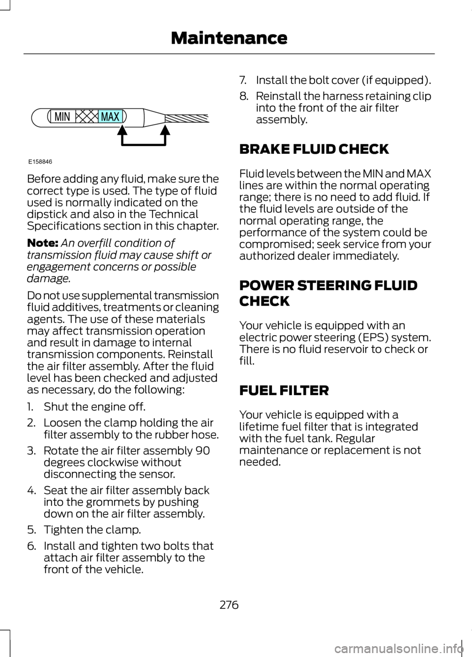
Before adding any fluid, make sure the
correct type is used. The type of fluid
used is normally indicated on the
dipstick and also in the Technical
Specifications section in this chapter.
Note:
An overfill condition of
transmission fluid may cause shift or
engagement concerns or possible
damage.
Do not use supplemental transmission
fluid additives, treatments or cleaning
agents. The use of these materials
may affect transmission operation
and result in damage to internal
transmission components. Reinstall
the air filter assembly. After the fluid
level has been checked and adjusted
as necessary, do the following:
1. Shut the engine off.
2. Loosen the clamp holding the air filter assembly to the rubber hose.
3. Rotate the air filter assembly 90 degrees clockwise without
disconnecting the sensor.
4. Seat the air filter assembly back into the grommets by pushing
down on the air filter assembly.
5. Tighten the clamp.
6. Install and tighten two bolts that
attach air filter assembly to the
front of the vehicle. 7.
Install the bolt cover (if equipped).
8. Reinstall the harness retaining clip
into the front of the air filter
assembly.
BRAKE FLUID CHECK
Fluid levels between the MIN and MAX
lines are within the normal operating
range; there is no need to add fluid. If
the fluid levels are outside of the
normal operating range, the
performance of the system could be
compromised; seek service from your
authorized dealer immediately.
POWER STEERING FLUID
CHECK
Your vehicle is equipped with an
electric power steering (EPS) system.
There is no fluid reservoir to check or
fill.
FUEL FILTER
Your vehicle is equipped with a
lifetime fuel filter that is integrated
with the fuel tank. Regular
maintenance or replacement is not
needed.
276
MaintenanceE158846
Page 281 of 474
Your vehicle is equipped with a
Motorcraft® maintenance-free
battery which normally does not
require additional water during its life
of service.
Note:
If your battery has a
cover/shield, make sure it is reinstalled
after the battery has been cleaned or
replaced.
For longer, trouble-free operation,
keep the top of the battery clean and
dry. Also, make certain the battery
cables are always tightly fastened to
the battery terminals.
If you see any corrosion on the battery
or terminals, remove the cables from
the terminals and clean with a wire
brush. You can neutralize the acid with
a solution of baking soda and water.
It is recommended that the negative
battery cable terminal be
disconnected from the battery if you
plan to store your vehicle for an
extended period of time.
To ensure proper operation of the
battery management system (BMS),
any electrical devices that are added
to the vehicle should not have their
ground connection made directly at
the negative battery post. A
connection at the negative battery
post can cause inaccurate
measurements of the battery
condition and potential incorrect
system operation. Note:
Electrical or electronic
accessories or components added to
the vehicle by the dealer or the owner
may adversely affect battery
performance and durability and may
also affect the performance of other
electrical systems in the vehicle.
When a battery replacement is
required, the battery should only be
replaced with a Ford recommended
replacement battery that matches
the electrical requirements of the
vehicle.
When the battery is disconnected or
a new battery installed, the automatic
transmission must relearn its adaptive
strategy. As a result of this, the
transmission may shift firmly when
first driven. This operation is
considered normal and will fully
update transmission operation to its
optimum shift feel.
If the battery has been disconnected
or a new battery has been installed,
the clock and the preset radio stations
must be reset once the battery is
reconnected.
Note: Always dispose of automotive
batteries in a responsible manner.
Follow your local authorized standards
for disposal. Call your local authorized
recycling center to find out more about
recycling automotive batteries.
278
Maintenance
Page 285 of 474
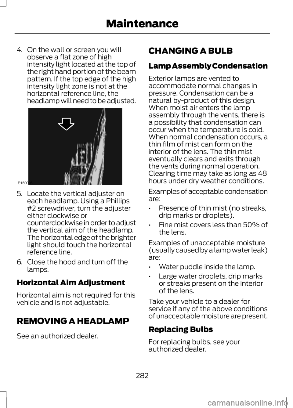
4. On the wall or screen you will
observe a flat zone of high
intensity light located at the top of
the right hand portion of the beam
pattern. If the top edge of the high
intensity light zone is not at the
horizontal reference line, the
headlamp will need to be adjusted. 5. Locate the vertical adjuster on
each headlamp. Using a Phillips
#2 screwdriver, turn the adjuster
either clockwise or
counterclockwise in order to adjust
the vertical aim of the headlamp.
The horizontal edge of the brighter
light should touch the horizontal
reference line.
6. Close the hood and turn off the
lamps.
Horizontal Aim Adjustment
Horizontal aim is not required for this
vehicle and is not adjustable.
REMOVING A HEADLAMP
See an authorized dealer. CHANGING A BULB
Lamp Assembly Condensation
Exterior lamps are vented to
accommodate normal changes in
pressure. Condensation can be a
natural by-product of this design.
When moist air enters the lamp
assembly through the vents, there is
a possibility that condensation can
occur when the temperature is cold.
When normal condensation occurs, a
thin film of mist can form on the
interior of the lens. The thin mist
eventually clears and exits through
the vents during normal operation.
Clearing time may take as long as 48
hours under dry weather conditions.
Examples of acceptable condensation
are:
•
Presence of thin mist (no streaks,
drip marks or droplets).
• Fine mist covers less than 50% of
the lens.
Examples of unacceptable moisture
(usually caused by a lamp water leak)
are:
• Water puddle inside the lamp.
• Large water droplets, drip marks
or streaks present on the interior
of the lens.
Take your vehicle to a dealer for
service if any of the above conditions
of unacceptable moisture are present.
Replacing Bulbs
For replacing bulbs, see your
authorized dealer.
282
MaintenanceE150095
Page 292 of 474
Note:
To check for compatibility, first
test any cleaner or stain remover on an
inconspicuous part of the leather.
You should:
• remove dust and loose dirt with a
vacuum cleaner.
• clean spills and stains as quickly
as possible.
• To check for compatibility, first
test any cleaner or stain remover
on an inconspicuous part of the
leather.
Do not use the following products as
these may damage the leather:
• oil/petroleum-based leather
conditioners.
• household cleaners.
• alcohol solutions.
• solvents or cleaners intended for
rubber, vinyl and plastics.
CLEANING THE ALLOY
WHEELS
Note: Do not apply a cleaning
chemical to warm or hot wheel rims
and covers.
Note: Some automatic car washes
may cause damage to the finish on
your wheel rims and covers.
Note: Industrial-strength (heavy-duty)
cleaners or cleaning chemicals, in
combination with brush agitation to
remove brake dust and dirt, could wear
away the clear coat finish over a period
time. Note:
Do not use hydrofluoric
acid-based or high caustic-based
wheel cleaners, steel wool, fuels or
strong household detergents.
Note: If you intend parking your vehicle
for an extended period after cleaning
the wheels with a wheel cleaner, drive
your vehicle for a few minutes before
doing so. This will reduce the risk of
increased corrosion of the brake discs.
Alloy wheels and wheel covers are
coated with a clear coat paint finish.
To maintain their condition we
recommend that you:
• Clean the wheels weekly, with the
recommended Ford service wheel
and tire cleaner. Apply using
manufacturer's instructions. Use
Motorcraft® Wheel and Tire
Cleaner. See cleaning products
(page ?).
• Use a sponge to remove heavy
deposits of dirt and brake dust
accumulation.
• Rinse thoroughly with a strong
stream of water when you have
completed the cleaning process.
• To remove tar and grease, use
Motorcraft® Bug and Tar Remover.
See cleaning products (page ?).
VEHICLE STORAGE
If you plan on storing your vehicle for
an extended period of time (30 days
or more), read the following
maintenance recommendations to
make sure your vehicle stays in good
operating condition.
289
Vehicle Care
Page 303 of 474
Changing Tires with a Tire
Pressure Monitoring System
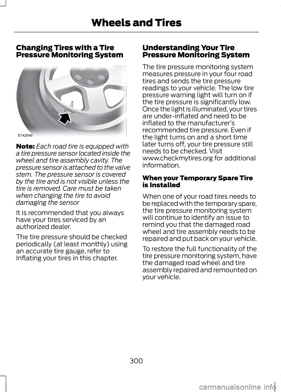
Note:
Each road tire is equipped with
a tire pressure sensor located inside the
wheel and tire assembly cavity. The
pressure sensor is attached to the valve
stem. The pressure sensor is covered
by the tire and is not visible unless the
tire is removed. Care must be taken
when changing the tire to avoid
damaging the sensor
It is recommended that you always
have your tires serviced by an
authorized dealer.
The tire pressure should be checked
periodically (at least monthly) using
an accurate tire gauge, refer to
Inflating your tires in this chapter. Understanding Your Tire
Pressure Monitoring System
The tire pressure monitoring system
measures pressure in your four road
tires and sends the tire pressure
readings to your vehicle. The low tire
pressure warning light will turn on if
the tire pressure is significantly low.
Once the light is illuminated, your tires
are under-inflated and need to be
inflated to the manufacturer
’s
recommended tire pressure. Even if
the light turns on and a short time
later turns off, your tire pressure still
needs to be checked. Visit
www.checkmytires.org for additional
information.
When your Temporary Spare Tire
is Installed
When one of your road tires needs to
be replaced with the temporary spare,
the tire pressure monitoring system
will continue to identify an issue to
remind you that the damaged road
wheel and tire assembly needs to be
repaired and put back on your vehicle.
To restore the full functionality of the
tire pressure monitoring system, have
the damaged road wheel and tire
assembly repaired and remounted on
your vehicle.
300
Wheels and TiresE142549
Page 308 of 474
Treadwear
The treadwear grade is a comparative
rating based on the wear rate of the
tire when tested under controlled
conditions on a specified government
test course. For example, a tire graded
150 would wear one and one-half (1
½) times as well on the government
course as a tire graded 100. The
relative performance of tires depends
upon the actual conditions of their
use, however, and may depart
significantly from the norm due to
variations in driving habits, service
practices, and differences in road
characteristics and climate.
Traction AA A B C
WARNING
The traction grade assigned to
this tire is based on
straight-ahead braking traction tests,
and does not include acceleration,
cornering, hydroplaning or peak
traction characteristics. The traction grades, from highest to
lowest are AA, A, B, and C. The grades
represent the tire
’s ability to stop on
wet pavement as measured under
controlled conditions on specified
government test surfaces of asphalt
and concrete. A tire marked C may
have poor traction performance. Temperature A B C WARNING
The temperature grade for this
tire is established for a tire that
is properly inflated and not
overloaded. Excessive speed,
underinflation, or excessive loading,
either separately or in combination,
can cause heat buildup and possible
tire failure. The temperature grades are A (the
highest), B and C, representing the
tire
’s resistance to the generation of
heat and its ability to dissipate heat
when tested under controlled
conditions on a specified indoor
laboratory test wheel. Sustained high
temperature can cause the material
of the tire to degenerate and reduce
tire life, and excessive temperature
can lead to sudden tire failure. The
grade C corresponds to a level of
performance which all passenger car
tires must meet under the Federal
Motor Vehicle Safety Standard No.
139. Grades B and A represent higher
levels of performance on the
laboratory test wheel than the
minimum required by law.
305
Wheels and Tires
Page 310 of 474
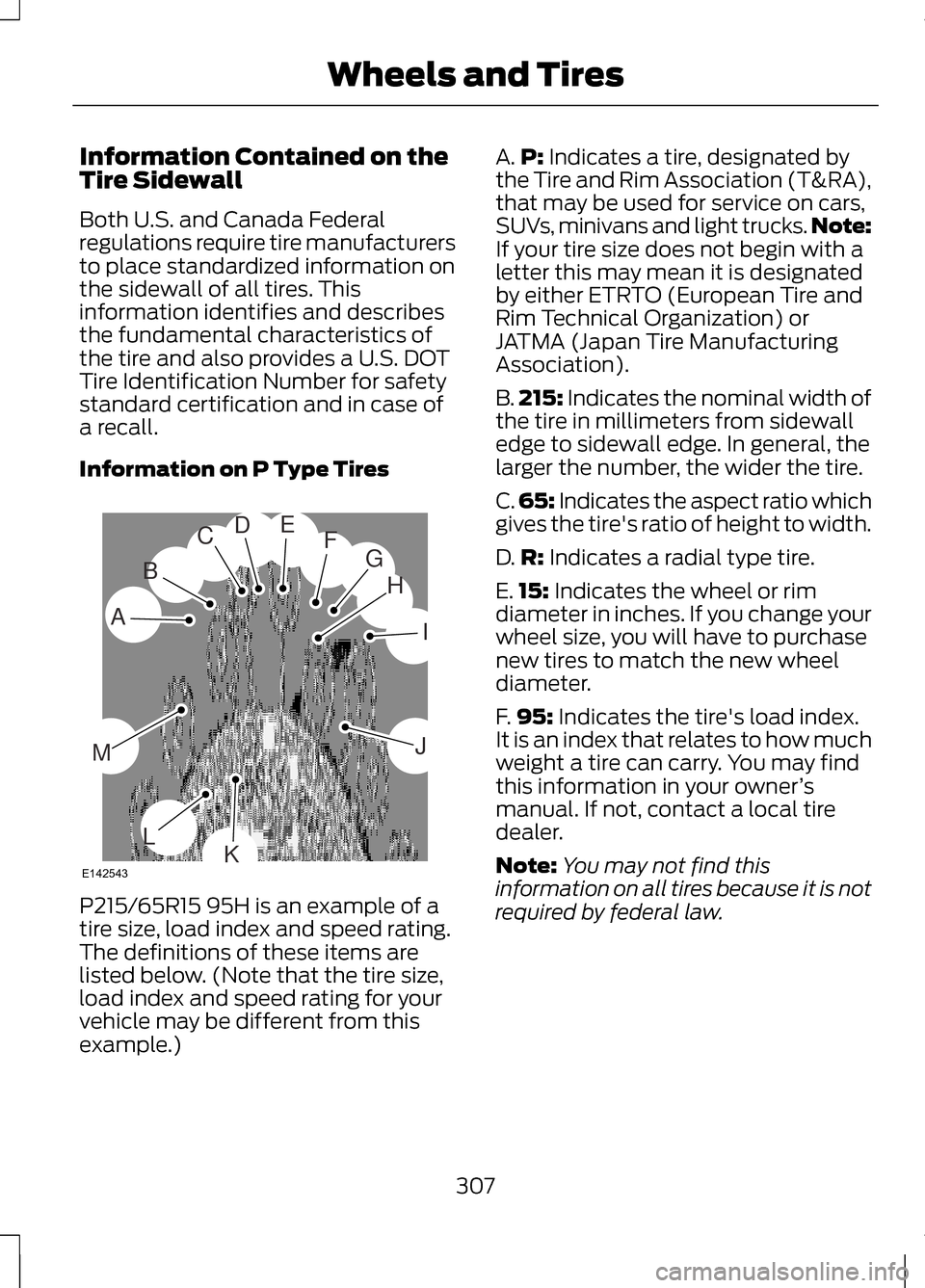
Information Contained on the
Tire Sidewall
Both U.S. and Canada Federal
regulations require tire manufacturers
to place standardized information on
the sidewall of all tires. This
information identifies and describes
the fundamental characteristics of
the tire and also provides a U.S. DOT
Tire Identification Number for safety
standard certification and in case of
a recall.
Information on P Type Tires
P215/65R15 95H is an example of a
tire size, load index and speed rating.
The definitions of these items are
listed below. (Note that the tire size,
load index and speed rating for your
vehicle may be different from this
example.) A.
P: Indicates a tire, designated by
the Tire and Rim Association (T&RA),
that may be used for service on cars,
SUVs, minivans and light trucks. Note:
If your tire size does not begin with a
letter this may mean it is designated
by either ETRTO (European Tire and
Rim Technical Organization) or
JATMA (Japan Tire Manufacturing
Association).
B. 215:
Indicates the nominal width of
the tire in millimeters from sidewall
edge to sidewall edge. In general, the
larger the number, the wider the tire.
C. 65: Indicates the aspect ratio which
gives the tire's ratio of height to width.
D. R:
Indicates a radial type tire.
E. 15:
Indicates the wheel or rim
diameter in inches. If you change your
wheel size, you will have to purchase
new tires to match the new wheel
diameter.
F. 95:
Indicates the tire's load index.
It is an index that relates to how much
weight a tire can carry. You may find
this information in your owner ’s
manual. If not, contact a local tire
dealer.
Note: You may not find this
information on all tires because it is not
required by federal law.
307
Wheels and TiresH
I
J
KL
M
A
B
CDEFG
E142543
Page 313 of 474
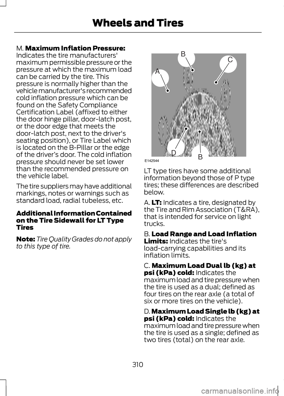
M.
Maximum Inflation Pressure:
Indicates the tire manufacturers'
maximum permissible pressure or the
pressure at which the maximum load
can be carried by the tire. This
pressure is normally higher than the
vehicle manufacturer's recommended
cold inflation pressure which can be
found on the Safety Compliance
Certification Label (affixed to either
the door hinge pillar, door-latch post,
or the door edge that meets the
door-latch post, next to the driver's
seating position), or Tire Label which
is located on the B-Pillar or the edge
of the driver ’s door. The cold inflation
pressure should never be set lower
than the recommended pressure on
the vehicle label.
The tire suppliers may have additional
markings, notes or warnings such as
standard load, radial tubeless, etc.
Additional Information Contained
on the Tire Sidewall for LT Type
Tires
Note: Tire Quality Grades do not apply
to this type of tire. LT type tires have some additional
information beyond those of P type
tires; these differences are described
below.
A.
LT: Indicates a tire, designated by
the Tire and Rim Association (T&RA),
that is intended for service on light
trucks.
B. Load Range and Load Inflation
Limits:
Indicates the tire's
load-carrying capabilities and its
inflation limits.
C. Maximum Load Dual lb (kg) at
psi (kPa) cold:
Indicates the
maximum load and tire pressure when
the tire is used as a dual; defined as
four tires on the rear axle (a total of
six or more tires on the vehicle).
D. Maximum Load Single lb (kg) at
psi (kPa) cold:
Indicates the
maximum load and tire pressure when
the tire is used as a single; defined as
two tires (total) on the rear axle.
310
Wheels and TiresA
BC
BDE142544