MAZDA 232 1990 Suplement Repair Manual
Manufacturer: MAZDA, Model Year: 1990, Model line: 232, Model: MAZDA 232 1990Pages: 677, PDF Size: 61.19 MB
Page 51 of 677
Bl INSTALLATION
93GOE 1-73;
03UOBX-84
. .
â, .
L .G,
. . â?.
- -. _ .:
.L â.. :-.:
.-_: _. _, _-
.
-_
. :
Cl :- . .
: .._.
. . ._-
;: , â. â
,.. .- -
. âL,
93GO3 l-73â
-DEFLECTiON CHfiCKIN:
g3GOBj-717
Bl-22
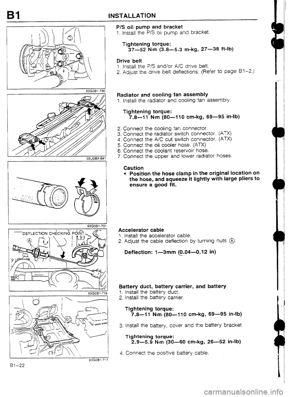
P/S oil pump and bracket
1. Install the P/S oil pump and bracket.
Tightening torque:
37-52 N-m (3.8-5.3 m-kg, 27-38 ft-lb)
Drive belt
I. fnstall the P/S and/or A/C drive belt.
2. Adjust the drive belt deflections. (Refer to page Bl-2.)
Radiator
and cooling fan assembly
f . Install the radiator and cooling fan assembly.
Tightening torque:
7.8-I 1 N-m (80-I 10 cm-kg, 69-95 in-lb)
2.. Connect the cooling fan connector.
3. Connect the radiator switch connector.
4. Connect the A/C cut switch connector.
5. Connect the oil cooler hose. (ATX)
6. Connect the coolant reservoir hose.
7. Connect the upper and lower radiator
@TX)
Pm
hoses.
Caution
l Position the hose clamp in the original location on
the hose, and squeeze it tightly with large pliers to
ensure a good fit.
Accelerator cable
I. Install the accelerator cable.
2. Adjust the cable deflection by turning nuts @
Deflection: I-3mm (0.04--0.12 in)
-
Battery duct, battery carrier, and battery
I_ install the battery duct.
2. Install the battery carrier.
Tightening torque:
7.8-I 1 N-m (80-110 cm-kg, 69-95 in-lb)
3. Install the battery, cover and the battery bracket.
Tightening torque:
2.9-5.9 N-m (30-60 cm-kg, 26-52 in-lb)
4. Connect the positive battery cable.
Page 52 of 677
INSTALLATION Bl
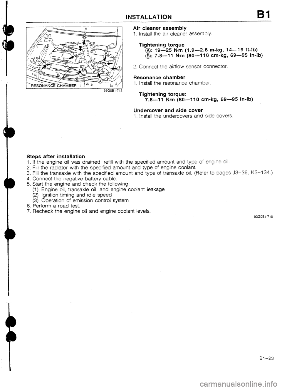
Air cleaner assembly
1. Install the air cleaner assembly.
Tightening torque
@: 19-25 Nm (I-9-2.6 m-kg, 14-19 Mb)
@: 7.8-11 Nm (80~-110 cm-kg, 69-95 in-lb)
2. Connect the airflow sensor connector.
Resonance chamber
1. lnstail the resonance chamber.
Tightening torque:
7.8-W Nm (SO-11 0 cm-kg, 69-95 in-lb)
Undercover and side cuver
1. install the undercovers and side covers.
Steps after installation
1. If the engine oil was drained, refill with the specified amount and type of engine oil.
2. Fill the radiator with the specified amount and type of engine coolant.
3. Fill the transaxle with the specified amount and type of transaxle oil. (Refer to pages J3-36, K3-134.)
4. Connect the negative battery cable.
5. Start the engine and check the following:
(1) Engine oil, transaxle oil, and engine coolant leakage
(2) Ignition timing and idle speed
(3) Operation of emission control system
6. Perform a road test.
7. Recheck the engine oil and engine coolant levels.
93GOSi-719
al-23
Page 53 of 677
Page 54 of 677

B2
ENGINE
(DOHC)
INDEX . . . . . . . ..**......... . . . . . . . ...* . . . . . . . . . . . . . . . . . . . l . BZ- 2
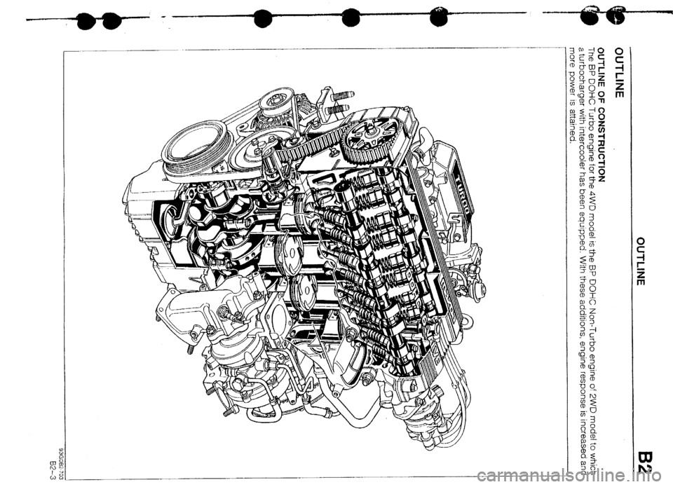
OUTLINE
................................................ BZ- 3
OUTLINE OF CONSTRUCTION.. .............. BZ- 3
SPEClFlCATlONS .................................. BZ- 4
INTERCHANGEABiLITY
.......................... BZ- 5
CYLINDER HEAD
.................................. BZ- 6
CYLINDER BLOCK AND OIL PAN ........... BZ- 7
PISTON ............................................... BZ- 8
FtYWtiEEL .......................................... BZ- 9
CAMSHAFT .......................................... BZ-10
SUPPLEMENTAL SERVICE INFORMATION BZ-11
COMPRESSION
....................................... 82-I 1
INSPECTION ........................................ B2-11
REMOVAL .............................................. BZ-12
PROCEDURE ........................................ BZ-12
ENGINE STAND MOUNTING.. ................... BZ-20
PROCEDURE ........................................ BZ-20
ENGINE STAND DISMOUNTING.. ..............
BZ-21
PROCEDURE ........................................ 82-21
INSTALLATION
....................................... BZ-23
PROCEDURE ........................................ BZ-23
93GOB2-701
Page 55 of 677

B2 INDEX
INDEX
~IMIY~ULU
TIGHTENING TORQUE
19-25 (1.9-2.6, 14-19)
/5--l ENGINE COMPRESSION
STANDARD
MINIMUM kPa (kglcm2, psi)-rpm
BP Turbo
I
1,059 (10.8, 1543-300
1 i-85 (8.0, 114)-300
EXHAUST MANlFOt
TIGHTENING TORQUE
DEFLECTION AT 98 N (IO kg, 22 Ib)
mm (in)
DRIVE BELT 1 NEW USED
ALTERNATOR 1 8.0-9.0 (0.31-U.35) 9.0-I 0.0 (0.35-U.39)
P/S, P/S + AIC ( 8.U-9.0 [O-31--0.35) 9.0-10.0 (0.35-0.39) 3826 3.9-A.?, -28134)
1. Engine
Removal -*-...-..I-*.* . ..wm._..... * e-e... -. page B2--I 2
Engine stand mounting ._.....__... page B2-20
Engine stand dismounting . . . . . . . page B2-21
Installation _ . . . . . . . . . . . . , . . _. . . . . . _. . . . . . . . , page EQ-23
BZ-2
Page 56 of 677
Page 57 of 677
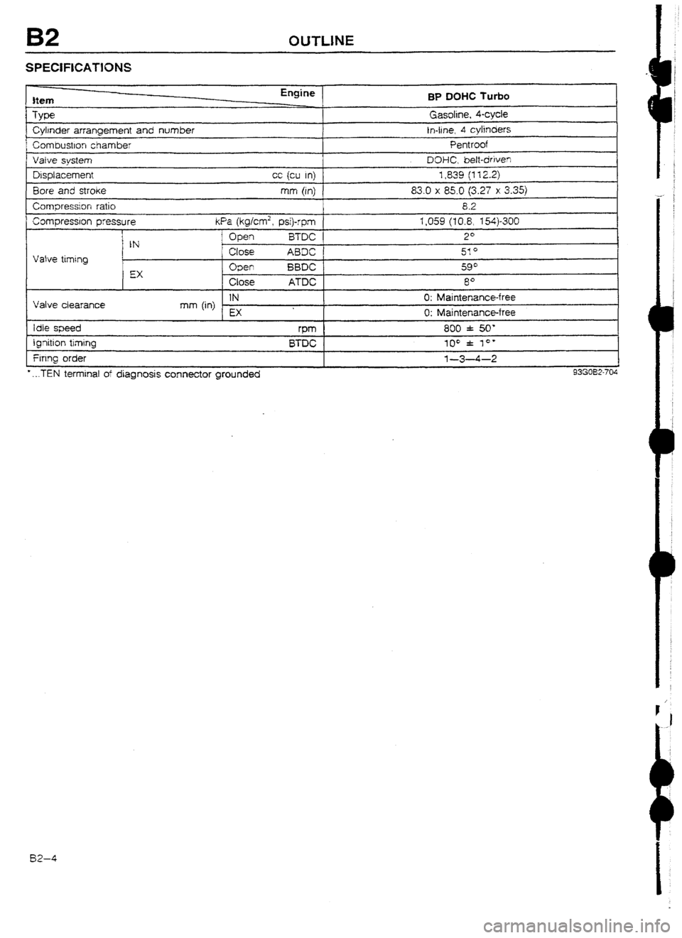
B2 OUTLINE
SPECIFICATlONS
Item
Type
Cylrnder arrangement and number
Corn bustlon chamber BP
DOHC Turbo
Gasoline, kycie
In-tine, 4 cylinders
Pentroof
I Vaive svstem I DOHC. bett-driven J
Displacement
Bore and stroke
Compression ratio cc {cu In) 1,839 (112.2)
mm (in) 83.0 x 85.0 (3.27 x 3.35)
8.2
Compression pressure kfa (kg/cmâ, psi)-rpm 1,059 (10.8, X4)-300
I
Vatve timing
I Open i3TDC 2*
IN
Close ABDC 51*
EX Open BBDC 59*
Close ATDC 8O
Valve ciearance IN 0: Maintenance-free
mm (in)
EX 0: Maintenance-free
Idle speed rPm 800 f 50'
ignition timing
Firing order
* . ..TEN terminal of diagnosis connector grounded BTDC 100 f lo* l-3-4-2
93G032-704 82-4
Page 58 of 677

c
OUTLINE B2
INTERCHANGEABILITY
The following chart shows interchangeability of the main park of the BP DOHC Turbo engine for the 4WD
model and the BP DOHC Non-Turbo engine for the 2WD model.
Symbols: 5 . Interchangeabie X . . . . Not Interchangeable
Part name interchangeability Remark
1 Cylinder head Shape different
Camshaft oil sea! :
Cylinder head bolt
3
Cyijnder head gasket cl
C$rnder head cover 0
1
Cylinder Cylinder head cover gasket cl
I
Cylinder block 0
block
related Man bearing cap 0
Main bearing support plate 3
OrI pan x Shape different
Trming belt cuver cl
Seal plate 3
Front oil seal I
3
Rear oil seal cl
Crankshaft â3
Main bearing 0
Thrust bearing 0
Connecting rod and cap 0
Connecting rod bearing I
0
Crankshaft [ Prston Shape different
related
Piston pin +-- -
c Piston ring cl
Crankshaft pulley 0
Rear cover 3
I Flywheel X Shape different
Flywheel bolt 0
Timing belt
cl
Timing belt Timing belt crank pulley
cl
Camshaft pulley 0 I
related
f Timing belt tensioner and spring
i 0
1, ldter
Camshaft
; Valve timing different
I-LA
Valve I Make - cl
Valve Exhaust 0
related
Vaive sprtng Intake 0
and seat
Exhaust 0
Valve guide cl
Valve seal 0
Oil pump 0
Oil pump gasket 0
Lubrication Oil strainer
0
system Oil strainer gasket
0
related
Oil cooler
0
Oil jet
0
Oil fitter
0
Water pump cl
Cooling
Thermostat
X system Specificatron drfferent
related Radiator X Specificatron different
Cooling fan
X Specification different
^^-^-^ m^- Ix?-5
Page 59 of 677

B2 OUTLINE
CYLINDER HEAD
INTAKE PORT 1 EXHAUST PORT
ENTlFlCATlON MARK
BP TURBO.. .BP26
BP NON-TURBO...BP05
The cylinder head for the BP DOHC Turbo engine is the same as for the BP DO% Non-Turbo engine! ex-
cept that the intake ports are shaped differently.
The identification mark is cast at the rear of the cyfinder head.
Identification:
BP DUHC Turbo
: BP26
BP DOHC
Non-Turbo: BP05
W-6
Page 60 of 677

OUTLINE B2
CYLfNDER BLOCK AND OIL PAN
I BP TURBO
I CONtiECTOR BOLT
BP TURBO
A CYLINDER BLOCK
BLIND PLUG
OIL RtiURN
PIPE
1
93GCB2-7C
The cylinder block is no different. But in conjunction with the newly provided turbocharger, the coolant, and
Mxication oil passages on the cylinder block are used.
Tfie oil pan has a provision for oil to return from the turbocharger.
BZ-7