4WD MAZDA 6 2002 Workshop Manual Suplement
[x] Cancel search | Manufacturer: MAZDA, Model Year: 2002, Model line: 6, Model: MAZDA 6 2002Pages: 909, PDF Size: 17.16 MB
Page 770 of 909

R–8
WHEEL ALIGNMENT
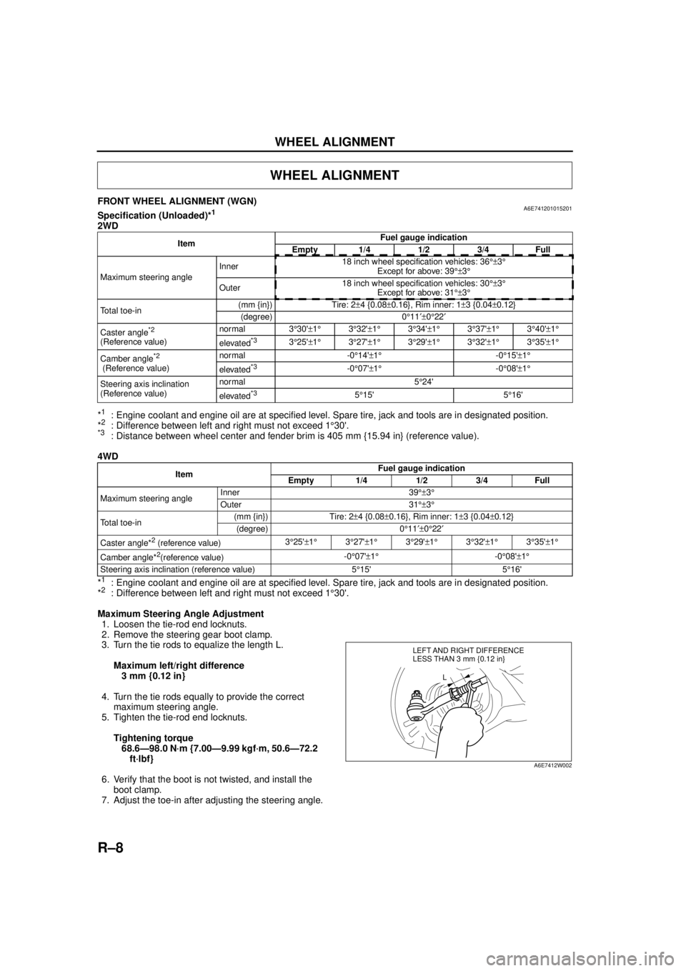
FRONT WHEEL ALIGNMENT (WGN)A6E741201015201Specification (Unloaded)*1
2WD
*
1: Engine coolant and engine oil are at specified level. Spare tire, jack and tools are in designated position.
*2: Difference between left and right must not exceed 1 °30'.*3: Distance between wheel center and fender brim is 405 mm {15.94 in} (reference value).
4WD
*
1: Engine coolant and engine oil are at specified level. Spare tire, jack and tools are in designated position.
*2: Difference between left and right must not exceed 1 °30'.
Maximum Steering Angle Adjustment 1. Loosen the tie-rod end locknuts.
2. Remove the steering gear boot clamp.
3. Turn the tie rods to equalize the length L.
Maximum left/right difference3 mm {0.12 in}
4. Turn the tie rods equally to provide the correct maximum steering angle.
5. Tighten the tie-rod end locknuts.
Tightening torque68.6—98.0 N·m {7.00—9.99 kgf·m, 50.6—72.2 ft·lbf}
6. Verify that the boot is not twisted, and install the boot clamp.
7. Adjust the toe-in after adjusting the steering angle.
WHEEL ALIGNMENT
Item Fuel gauge indication
Empty 1/4 1/2 3/4 Full
Maximum steering angle Inner
18 inch wheel specification vehicles: 36
°±3°
Except for above: 39 °±3°
Outer 18 inch wheel specification vehicles: 30
°±3°
Except for above: 31 °±3°
Total toe-in (mm {in}) Tire: 2
±4 {0.08 ±0.16}, Rim inner: 1 ±3 {0.04 ±0.12}
(degree) 0 °11 ′±0°22 ′
Caster angle
*2
(Reference value) normal 3
°30' ±1 ° 3°32' ±1 ° 3°34' ±1° 3°37' ±1° 3°40' ±1 °
elevated*33 °25' ±1 ° 3°27' ±1 ° 3°29' ±1° 3°32' ±1° 3°35' ±1 °
Camber angle
*2
(Reference value) normal -0
°14' ±1 ° -0°15' ±1°
elevated*3-0 °07' ±1 ° -0°08' ±1°
Steering axis inclination
(Reference value) normal 5
°24'
elevated
*35 °15' 5 °16'
Item Fuel gauge indication
Empty 1/4 1/2 3/4 Full
Maximum steering angle Inner 39
°±3°
Outer 31 °±3°
Total toe-in (mm {in}) Tire: 2
±4 {0.08 ±0.16}, Rim inner: 1 ±3 {0.04 ±0.12}
(degree) 0 °11 ′±0°22 ′
Caster angle*
2 (reference value) 3
°25' ±1 ° 3°27' ±1 ° 3°29' ±1 ° 3°32' ±1 ° 3°35' ±1 °
Camber angle*
2(reference value) -0
°07' ±1 ° -0°08' ±1°
Steering axis inclination (reference value) 5 °15' 5 °16'
LEFT AND RIGHT DIFFERENCE
L
LESS THAN 3 mm {0.12 in}
A6E7412W002
Page 771 of 909

WHEEL ALIGNMENT
R–9
R
Total Toe-in Adjustment
1. Center the steering wheel and confirm that the vehicle wheels/tires are pointing straight.
2. Loosen the left and right tie-rod end locknuts and turn the tie-rods equally. Both tie rods are right threaded, so
turning the right tie-rod toward the front of the vehicle and the left toward the rear increases toe-in.
Note
•Turning both tie-rods one complete turn changes toe-in by about 6 mm {0.24 in} (0°36').
3. Tighten the tie-rod end locknuts to the specified torque.
Tightening torque
68.6—98.0 N·m {7.00—9.99 kgf·m, 50.6—72.2 ft·lbf}
4. Verify that the boot is not twisted, and install the boot clamp.
End Of Sie
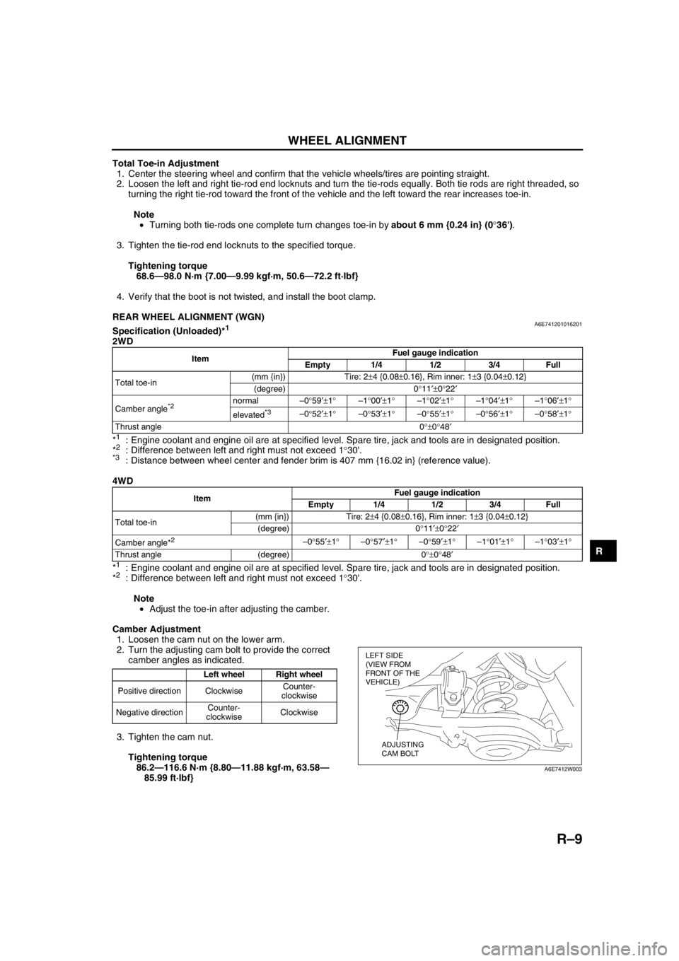
REAR WHEEL ALIGNMENT (WGN)A6E741201016201Specification (Unloaded)*1
2WD
*
1: Engine coolant and engine oil are at specified level. Spare tire, jack and tools are in designated position.
*2: Difference between left and right must not exceed 1°30'.*3: Distance between wheel center and fender brim is 407 mm {16.02 in} (reference value).
4WD
*
1: Engine coolant and engine oil are at specified level. Spare tire, jack and tools are in designated position.
*2: Difference between left and right must not exceed 1°30'.
Note
•Adjust the toe-in after adjusting the camber.
Camber Adjustment
1. Loosen the cam nut on the lower arm.
2. Turn the adjusting cam bolt to provide the correct
camber angles as indicated.
3. Tighten the cam nut.
Tightening torque
86.2—116.6 N·m {8.80—11.88 kgf·m, 63.58—
85.99 ft·lbf}
ItemFuel gauge indication
Empty 1/4 1/2 3/4 Full
Total toe-in(mm {in}) Tire: 2±4 {0.08±0.16}, Rim inner: 1±3 {0.04±0.12}
(degree) 0°11′±0°22′
Camber angle
*2 normal–0°59′±1°–1°00′±1°–1°02′±1°–1°04′±1°–1°06′±1°
elevated
*3–0°52′±1°–0°53′±1°–0°55′±1°–0°56′±1°–0°58′±1°
Thrust angle 0°±0°48′
ItemFuel gauge indication
Empty 1/4 1/2 3/4 Full
Total toe-in(mm {in}) Tire: 2±4 {0.08±0.16}, Rim inner: 1±3 {0.04±0.12}
(degree) 0°11′±0°22′
Camber angle*
2 –0°55′±1°–0°57′±1°–0°59′±1°–1°01′±1°–1°03′±1°
Thrust angle (degree) 0°±0°48′
Left wheel Right wheel
Positive direction ClockwiseCounter-
clockwise
Negative directionCounter-
clockwiseClockwise
LEFT SIDE
(VIEW FROM
FRONT OF THE
VEHICLE)
ADJUSTING
CAM BOLT
A6E7412W003
Page 775 of 909

REAR SUSPENSION
R–13
R
REAR STABILIZER REMOVAL/INSTALLATION (4WD)A6E7416281002011. Remove the rear auto leveling sensor.
(See T–20 REAR AUTO LEVELING SENSOR REMOVAL/INSTALLATION.)
2. Remove in the order indicated in the table.
3. Install in the reverse order of removal.
4. Adjust the headlight zeroset.
.
Bolt (Differential Front Side) Removal Note
1. Disconnect differential oil temperature sensor connector and 4WD solenoid connector.
2. Support the differential with a jack as shown in
the figure.
3. Remove the bolt.
5
4
3
1
AA
2
6
GREASEGREASE
43.1—60.8
{4.40—6.19,
31.8—44.8}
74.5—104.9
{7.60—10.69, 54.95—77.37}
43.1—60.8
{4.40—6.19,
31.8—44.8}
RUBBER
GREASE
43.1—60.8
{4.40—6.19,
31.8—44.8}
N·m {kgf·m, ft·lbf} 75.5—94.5
{7.70—9.63, 55.7—69.6}
A6E74162007
1 Stabilizer control link
2 Coil spring component (One side only)
3 Stabilizer bracket
4 Bushing5 Bolt (Differential front side)
(See R–13 Bolt (Differential Front Side) Removal
Note)
(See R–14 Bolt (Differential Front Side) Installation
Note)
6 Rear stabilizer
JACK
A6E74162011
Page 776 of 909

R–14
REAR SUSPENSION
Bolt (Differential Front Side) Installation Note
1. Support the differential with a jack, and then
install the bolt.
2. Connect differential oil temperature sensor
connector and 4WD solenoid connector.
End Of SieTRAILING LINK REMOVAL/INSTALLATION (4WD)A6E741628200201
Caution
•Performing the following procedures without first removing the ABS wheel-speed sensor may
possibly cause an open circuit in the harness if it is pulled by mistake. Before performing the
following procedures, remove the ABS wheel-speed sensor (axle side) and fix it to an appropriate
place where the sensor will not be pulled by mistake while servicing the vehicle.
1. Remove in the order indicated in the table.
2. Install in the reverse order of removal.
3. Inspect the rear wheel alignment.
(See R–9 REAR WHEEL ALIGNMENT (WGN).)
JACK
A6E74162011
Page 778 of 909

R–16
REAR SUSPENSION
Bolt (Trailing Link Front Side) Removal Note
1. Support the trailing link with a jack.
Caution
•Removing the trailing link is dangerous.
The trailing link could fall and cause
serious injury or death. Verify that the
jack securely supports the trailing link.
2. Remove the bolts (trailing link front side).
Bolt (Lateral Link Outer Side) Removal Note
1. Loosen the bolt (lateral link inner side).
2. Remove the bolt (lateral link outer side).
Bolt (Lateral Link Outer Side) Installation Note
1. Tighten the bolt (lateral link outer side).
2. Tighten the bolt (lateral link inner side).
Tightening torque
86.2—116.6 N·m {8.80—11.88 kgf·m, 63.58—85.99 ft·lbf}
Bolt (Trailing Link Front Side) Installation Note
1. Support the trailing link with a jack.
2. Tighten the bolts (trailing link front side).
End Of SieREAR CROSSMEMBER REMOVAL/INSTALLATION (4WD)A6E741628400201
Caution
•Performing the following procedures without first removing the ABS wheel-speed sensor may
possibly cause an open circuit in the harness if it is pulled by mistake. Before performing the
following procedures, remove the ABS wheel-speed sensor (axle side) and fix it to an appropriate
place where the sensor will not be pulled by mistake while servicing the vehicle.
1. Remove the rear auto leveling sensor and harness.
(See T–20 REAR AUTO LEVELING SENSOR REMOVAL/INSTALLATION.)
2. Remove the middle pipe.
(See F1–30 EXHAUST SYSTEM REMOVAL/INSTALLATION.)
3. Remove in the order indicated in the table.
4. Install in the reverse order of removal.
5. Adjust the headlight zeroset.
6. Inspect the rear wheel alignment.
(See R–9 REAR WHEEL ALIGNMENT (WGN).)
JACK
A6E74162010
JACK
A6E74162010
Page 783 of 909

S–2
OUTLINE, EXTERIOR ATTACHMENT
OUTLINE OF CONSTRUCTIONA6E770201086201•The construction and operation of the body system is essentially carried over from that of the current Mazda6
(GG) model, except for the following features. (See Mazda6 Training Manual 3359-1*-02C)
End Of Sie
FEATURESA6E770201086202Improved Marketability
•A rear spoiler with a built in high-mount brake light has been adopted. (WGN)
•A roof rail has been adopted. (WGN)
•A tonneau cover with an attached net has been adopted. (WGN)
•A fixed rear seat cushion has been adopted. (4WD WGN)
End Of Sie
OUTLINEA6E772801092201•A rear spoiler with a built in high-mount brake light has been adopted.
•A roof rail has been adopted.
End Of Sie
STRUCTURAL VIEWA6E772801092202
.
End Of Sie
OUTLINE
EXTERIOR ATTACHMENT
1
2
A6E7728T101
1 Roof rail2 Rear spoiler
Page 785 of 909

S–4
SEAT
End Of Sie
OUTLINEA6E775257100201•A fixed rear seat cushion has been adopted. (4WD WGN)
End Of Sie
STRUCTURAL VIEWA6E775257100202
.
End Of Sie
SEAT
12
44
33
A6E77521101
1 Full flat fold down function (except 4WD WGN)
2 Fold down function (4WD WGN)3 Rear seat back
4 Rear seat cushion
Page 809 of 909

S–28
SEAT BELT
REAR SIDE SEAT BELT REMOVAL/INSTALLATIONA6E775057730201
Caution
•The rear side seat belt for 4WD models is equipped with a silencer to reduce abnormal noise while
driving. If the silencer is not installed in the proper position, the push knob may not function
properly. When attaching the silencer, be sure to attach it in the correct area as shown below.
Note
•Rear side seat belts are built into the rear seat back. See rear seat disassembly/assembly, to remove/
install the rear side seat belt.
1. Peel off the backing of the double-sided adhesive tape.
2. Attach double-sided adhesive tape to the silencer as shown.
End Of Sie
REAR CENTER SEAT BELT REMOVAL/INSTALLATIONA6E775057730202WGN
Caution
•The ELR has a spring that will unwind if the retractor's cover is removed. The spring cannot be
rewound by hand. If this occurs, the ELR will not work properly. Therefore, do not disassemble the
retractor.
1. Remove the headliner.
2. Remove the bolts.
3. Remove the rear center seat belt.
4. Install in the reverse order of removal.
End Of Sie
SEAT BELT
SILENCERRETRACTOR
mm {in} 29—35
{1.2—1.3}
-3—3
{-0.1—0.1} 60
{2.3} 60
{2.3}
60
{2.3}
60
{2.3}40
{1.5}
29—35
{1.2—1.3}
-3—3
{-0.1—0.1}
SILENCER RETRACTOR
60{2.3}
A6E77502101
39—78 N·m
{3.9—8.0 kgf·m, 29—57 ft·lbf}
REAR CENTER
SEAT BELT
BOLT
A6A7750W101
Page 810 of 909

SEAT
S–29
S
REAR SEAT REMOVAL/INSTALLATIONA6E7752572002014WD (WGN)
1. Remove in the order indicated in the table.
2. Install in the reverse order of removal.
.
Remote wire removal note
1. Turn over the trunk floor mat.
2. Remove the case.
3. Remove the remote wire.
End Of Sie
SEAT
3
2
1
1
A: 36.3—53.9 N·m
{3.71—5.49 kgf·m, 26.8—39.7 ft·lbf}
B: 38.3—78.4 N·m
{3.91—7.99 kgf·m, 28.3—57.8 ft·lbf}
A
A
B
B
A6E77521102
1 Remote wire
(See S–29 Remote wire removal note)2 Rear seat cushion
3 Rear seat back
CASE
REMOTE WIRE
A6E7752W014
Page 811 of 909

S–30
SEAT
REAR SEAT DISASSEMBLY/ASSEMBLYA6E775257200202WGN
1. Disassemble in the order indicated in the table.
2. Assemble in the reverse order of disassembly..
End Of Sie
9
1
6
9
8
7
25
4
2
5
4
3
1
6
87
19
18
18
1315
16
171110
11
22
21
20
14
21
2224
24
20
23
3
A
A
12
10
19
23
12
25
25
4WD
4
3
A6E77521015
1 Headrest
2 Hinge cover (2WD)
3 Seat cushion trim
4 Seat cushion pad
5 Seat cushion frame (2WD)
6 Remote button cover
7 Seat back catch cover
8 Child seat anchor cover
9 Retainer bar anchor
10 Seat back board
11 Pole guide
12 Remote button
13 Armrest assembly14 Cup holder
15 Armrest hinge
16 Armrest trim
17 Armrest pad
18 Seat back trim
19 Seat back pad
20 Seat belt guide
21 Retractor cover
22 Rear seat belt
23 Seat back catch
24 Remote wire
25 Seat back frame