4WD MAZDA 6 2002 Suplement Manual Online
[x] Cancel search | Manufacturer: MAZDA, Model Year: 2002, Model line: 6, Model: MAZDA 6 2002Pages: 909, PDF Size: 17.16 MB
Page 716 of 909

N–2
OUTLINE
OUTLINE OF CONSTRUCTIONA6E660201036201•The construction and operation of the steering system is essentially carried over from that of the current
Mazda6 (GG), except for the following features. (See Mazda6 Training Manual 3359-1*-02C.)
• Due to the addition of the MZR-CD (RF Turbo) engine, a gear-driven power steering oil pump has been
adopted. The operation of the oil pump is the same as that of the current Mazda6 (GG).
• The disassembly/assembly procedures for the steering gear and linkage of the newly equipped MZR-CD (RF
Turbo) engine, wagon and 4WD models are the same as that of the current Mazda6 (GG).
End Of Sie
FEATURESA6E660201036202Improved Steering Feel
• The fluid pressure characteristics of the power steering system has been optimized (MZR-CD (RF Turbo) and
4WD models).
End Of Sie
SPECIFICATIONSA6E660201036203
* : When reservoir tank is at maximum volume
Bold frame:New specifications
End Of Sie
OUTLINE
Item New Mazda6
(GG) (4SD, 5HB) New Mazda6 (GY) (Wagon) Current Mazda6
(GG) (4SD, 5HB)
Drive train 2WD 4WD 2WD
Steering
wheel Outer diameter
370 {14.6}
(mm {in})
Lock-to-lock 18 inch wheel specification vehicles: 2.65
Except for above: 2.75 2.75
(turns)
Steering gear
and linkage Type Rack-and-pinion
Rack stroke 18 inch wheel specification vehicles:
141.6—143.6 {5.57—5.65}
Except for above:146.8—148.8
{5.78—5.85} 146.8—148.8 {5.78—5.85}
(mm {in})
Steering
column and
shaft Shaft type Collapsible
Joint type 2-cross joint
Amount of tilt
45 {1.8}
(mm {in})
Amount of telescope
(If equipped) 50 {2.0}
(mm {in})
Powe r
steering
system Power assist type Engine speed sensing
Pow er
steering
fluid
Ty p e
M-
III or equivalent (e.g. Dexron®II)
Fluid capacity
*
(approximate
quantity) MTX (except MZR-CD (RF Turbo)):
0.80 {0.85, 0.70}
ATX: 0.87 {0.92, 0.77} MZR-CD (RF Turbo):
0.86 {0.91, 0.76} 0.89 {0.94, 0.78}
MTX:
0.80 {0.85, 0.70}
AT X :
0.87 {0.92, 0.77}
(L {US qt, Imp qt})
Page 718 of 909

N–4
OUTLINE
4WD
.
End Of Sie
8
7
5
4
3
1
2
6
5
6
8
7
A6E63162002
1 L.H.D.
2 R.H.D.
3 Steering wheel
4 Steering column and shaft5 Steering gear
6 Power steering oil pump
7 Fluid reservoir
8 Cooling pipe
Page 719 of 909

OUTLINE
N–5
N
SUPPLEMENTAL SERVICE INFORMATIONA6E660201034201•The following changes have been made since publication of the Mazda6 Workshop Manual (1730-1*-02C).
Power steering fluid
•Inspection procedure has been modified.
Steering gear and linkage (MZR-CD (RF Turbo))
•Removal/installation procedure has been added.
Steering gear and linkage (4WD)
•Removal/installation procedure has been added.
Power steering oil pump (MZR-CD (RF Turbo))
•Removal/installation procedure has been added.
•Disassembly/assembly procedure has been added.
End Of Sie
OUTLINE
Page 721 of 909

ENGINE SPEED SENSING POWER STEERING
N–7
N
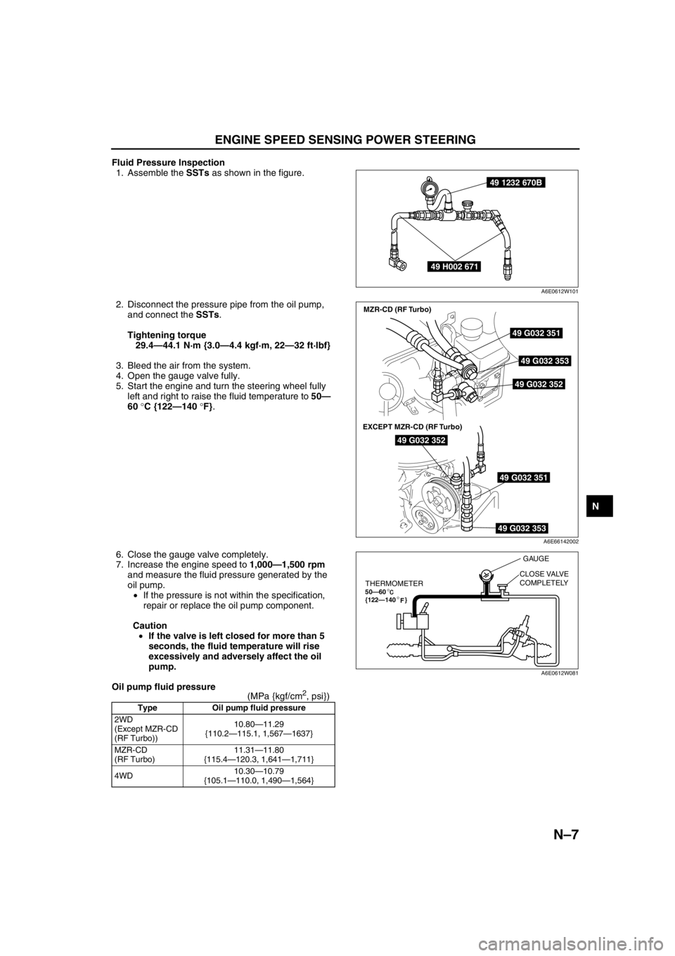
Fluid Pressure Inspection
1. Assemble the SSTs as shown in the figure.
2. Disconnect the pressure pipe from the oil pump,
and connect the SSTs.
Tightening torque
29.4—44.1 N·m {3.0—4.4 kgf·m, 22—32 ft·lbf}
3. Bleed the air from the system.
4. Open the gauge valve fully.
5. Start the engine and turn the steering wheel fully
left and right to raise the fluid temperature to 50—
60 °C {122—140 °F}.
6. Close the gauge valve completely.
7. Increase the engine speed to 1,000—1,500 rpm
and measure the fluid pressure generated by the
oil pump.
•If the pressure is not within the specification,
repair or replace the oil pump component.
Caution
•If the valve is left closed for more than 5
seconds, the fluid temperature will rise
excessively and adversely affect the oil
pump.
Oil pump fluid pressure
(MPa {kgf/cm
2, psi})
Type Oil pump fluid pressure
2WD
(Except MZR-CD
(RF Turbo))10.80—11.29
{110.2—115.1, 1,567—1637}
MZR-CD
(RF Turbo)11.31—11.80
{115.4—120.3, 1,641—1,711}
4WD10.30—10.79
{105.1—110.0, 1,490—1,564}
49 1232 670B
49 H002 671
A6E0612W101
49 G032 351
49 G032 353
49 G032 352
49 G032 352
49 G032 351
49 G032 353
MZR-CD (RF Turbo)
EXCEPT MZR-CD (RF Turbo)
A6E66142002
THERMOMETER50—60
{122—140 }°
°F
GAUGE
CLOSE VALVE
COMPLETELY
A6E0612W081
Page 722 of 909

N–8
ENGINE SPEED SENSING POWER STEERING
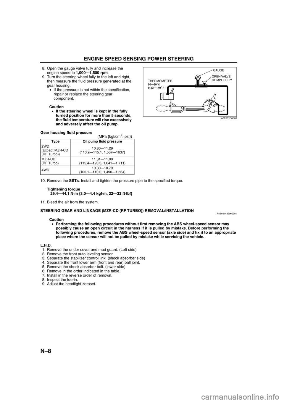
8. Open the gauge valve fully and increase the
engine speed to 1,000—1,500 rpm.
9. Turn the steering wheel fully to the left and right,
then measure the fluid pressure generated at the
gear housing.
•If the pressure is not within the specification,
repair or replace the steering gear
component.
Caution
•If the steering wheel is kept in the fully
turned position for more than 5 seconds,
the fluid temperature will rise excessively
and adversely affect the oil pump.
Gear housing fluid pressure
(MPa {kgf/cm
2, psi})
10. Remove the SSTs. Install and tighten the pressure pipe to the specified torque.
Tightening torque
29.4—44.1 N·m {3.0—4.4 kgf·m, 22—32 ft·lbf}
11. Bleed the air from the system.
End Of Sie
STEERING GEAR AND LINKAGE (MZR-CD (RF TURBO)) REMOVAL/INSTALLATIONA6E661432960201
Caution
•Performing the following procedures without first removing the ABS wheel-speed sensor may
possibly cause an open circuit in the harness if it is pulled by mistake. Before performing the
following procedures, remove the ABS wheel-speed sensor (axle side) and fix it to an appropriate
place where the sensor will not be pulled by mistake while servicing the vehicle.
L.H.D.
1. Remove the under cover and mud guard. (Left side)
2. Remove the front auto leveling sensor.
3. Separate the stabilizer control link. (shock absorber side)
4. Separate the front lower arm (front and rear) ball joint.
5. Remove the shock absorber bolt. (lower side)
6. Remove in the order indicated in the table.
7. Install in the reverse order of removal.
8. Inspect the toe-in.
9. Adjust the headlight zeroset.
Type Oil pump fluid pressure
2WD
(Except MZR-CD
(RF Turbo))10.80—11.29
{110.2—115.1, 1,567—1637}
MZR-CD
(RF Turbo)11.31—11.80
{115.4—120.3, 1,641—1,711}
4WD10.30—10.79
{105.1—110.0, 1,490—1,564}
THERMOMETER50—60
{122—140 }°
°F
GAUGE
OPEN VALVE
COMPLETELY
A6E0612W080
Page 727 of 909

ENGINE SPEED SENSING POWER STEERING
N–13
N
STEERING GEAR AND LINKAGE (4WD) REMOVAL/INSTALLATIONA6E661432960202
Caution
•Performing the following procedures without first removing the ABS wheel-speed sensor may
possibly cause an open circuit in the harness if it is pulled by mistake. Before performing the
following procedures, remove the ABS wheel-speed sensor (axle side) and fix it to an appropriate
place where the sensor will not be pulled by mistake while servicing the vehicle.
1. Remove the under cover and mud guard. (Left side)
2. Remove the front auto leveling sensor.
3. Separate the stabilizer control link. (shock absorber side)
4. Separate the front lower arm (front and rear) ball joint.
5. Remove the shock absorber bolt. (lower side)
6. Remove in the order indicated in the table.
7. Install in the reverse order of removal.
8. Inspect the toe-in.
9. Adjust the headlight zeroset.
Page 735 of 909

P–2
OUTLINE
OUTLINE OF CONSTRUCTIONA6E690201020201•The construction and operation of the braking system is the same as that of the current Mazda6 (GG) L8, LF,
L3 engine 2WD model, except for the following features. (See Mazda6 Training Manual 3359-1*-02C.)
End Of Sie
FEATURESA6E690201020202Modifications to match vehicle characteristics
•Due to the addition of the MZR-CD (RF Turbo) engine, the vacuum pump and vacuum switch have been
added.
•Due to the addition of the 4WD model, DSC HU/CM uses the forward-G signal from combine sensor to control
DSC.
End Of Sie
SPECIFICATIONSA6E690201020203
Bold frames: New specifications
End Of Sie
OUTLINE
ItemSpecification
New Mazda6 (GG, GW) Current Mazda6 (GG)
Brake pedalType Suspended
Pedal lever ratio 2.7
Max. stroke (mm {in}) 128.5 {5.06}
Master
cylinderType Tandem (with level sensor)
Cylinder diameter (mm {in}) 20.64 {0.813}
Front disc
brakeType Ventilated disc
Cylinder bore (mm {in}) 57.15 {2.250}
Pad dimensions (area × thickness) L8, LF (GCC specs.):
4,220 {6.75} × 10.0 {0.39}
LF (European (L.H.D. U.K.)
specs.), L3, MZR-CD (RF Turbo):
4,010 {6.42} × 12.0 {0.47}L8, LF (GCC specs.):
4,220 {6.75} × 10.0 {0.39}
LF (European (L.H.D. U.K.) specs.),
L3: 4,010 {6.42} × 12.0 {0.47} (mm
2 {in2} × mm {in})
Disc plate dimensions
(outer diameter × thickness)L8, LF (GCC specs.):
274 {10.8} × 24.0 {0.945}
LF (European (L.H.D. U.K.)
specs.), L3, MZR-CD (RF Turbo):
283 {11.1} × 25.0 {0.984}L8, LF (GCC specs.):
274 {10.8} × 24.0 {0.945}
LF (European (L.H.D. U.K.) specs.),
L3: 283 {11.1} × 25.0 {0.984} (mm {in} × mm {in})
Rear brake
(disc)Type Solid disc
Cylinder bore (mm {in}) 34.93 {1.375}
Pad dimensions (area × thickness)
2,810 {4.51} × 8.0 {0.31}
(mm
2 {in2} × mm {in})
Disc plate dimensions
(outer diameter × thickness)
280 {11.0} × 10.0 {0.39}
(mm {in})
Power brake
unitType Vacuum multiplier, single diaphragm
Diameter (mm {in}) 279 {10.9}
Braking force
control deviceTypeWith ABS: EBD (Electronic Brakeforce Distribution)
Without ABS: Dual proportioning valve
Parking brakeType Mechanical two-rear-wheel control
Operation system Center lever type
Brake fluid TypeEuropean (L.H.D. U.K.) specs.: SAE J1703, FMVSS116 DOT3 OR DOT4
GCC specs.: SAE J1703, FMVSS116 DOT3
Page 738 of 909

ABS/TCS
P–5
P
System Diagram
.
End Of Sie
9
9
8
7
5
43
12
6
18
17
15
16
14
13
11
12
RF
FL
RR
RL
PCMG
E
FI Z
U
D
A
B
C
Y
AC
X
V O
R ADAB AA
ABS/TCS HU/CM
pP
9
10
19
920
A6E6921W201
1 IG switch
2SUS 15 A fuse
3 ABS 60 A fuse
4 Meter
5 ABS warning light
6 Brake system warning light
7 TCS OFF light
8 TCS indicator light
9CAN driver
10 Brake light11 Cruise actuator
12 TCS OFF switch
13 DLC-2
14 CAN-H
15 CAN-L
16 ABS Wheel-speed sensor
17 Battery
18 Brake switch
19 Audio unit, Wiper and washer switch, Car-navigation
unit, Auto leveling control unit
20 TCM, 4WD CM
Page 739 of 909

P–6
DYNAMIC STABILITY CONTROL
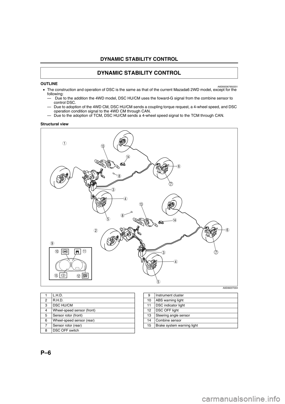
OUTLINEA6E692067650201•The construction and operation of DSC is the same as that of the current Mazada6 2WD model, except for the
following:
— Due to the addition the 4WD model, DSC HU/CM uses the foward-G signal from the combine sensor to
control DSC.
—Due to adoption of the 4WD CM, DSC HU/CM sends a coupling torque request, a 4-wheel speed, and DSC
operation condition signal to the 4WD CM through CAN.
—Due to the adoption of TCM, DSC HU/CM sends a 4-wheel speed signal to the TCM through CAN.
Structural view
.
DYNAMIC STABILITY CONTROL
7
5
4
3
1
2
14
13
6
13
12
5
4
3
7
6
1011
9
14
8
8
15
A6E6920T004
1 L.H.D.
2 R.H.D.
3 DSC HU/CM
4 Wheel-speed sensor (front)
5 Sensor rotor (front)
6 Wheel-speed sensor (rear)
7 Sensor rotor (rear)
8 DSC OFF switch9 Instrument cluster
10 ABS warning light
11 DSC indicator light
12 DSC OFF light
13 Steering angle sensor
14 Combine sensor
15 Brake system warning light
Page 740 of 909

DYNAMIC STABILITY CONTROL
P–7
P
Wiring Diagram
.
9
RF
FL
RR
RL
PCM
G
E
M
I
F
K
H
Q
NJ
P
S
T
V
O
Y
X
W
U
R
L
Z
AC
D
B
AG
AF
AE
AC
AA
AB
C
F
D
A
B
EDSC HU/CM
A
B
C
D
F
1
3
2
8
7
5
4
6
9
9
9
10
11
13
12
15
14
18
17
16
1920
2122
24
23
A6E6921W203
1 IG switch
2SUS 15A fuse
3 ABS 60 A fuse
4 Meter
5 ABS warning light
6 Brake system warning light
7 DSC OFF light
8 DSC indicator light
9CAN driver
10 Battery
11 Cruise actuator
12 DSC OFF switch13 DLC-2
14 CAN-H
15 CAN-L
16 Wheel-speed sensor
17 Combine sensor
18 Steering angle sensor
19 Brake switch
20 Brake light
21 Back-up light switch (MTX only)
22 Back-up light (MTX only)
23 Audio unit, Wiper and washer switch, Car-navigation
unit, Auto leveling control unit
24 TCM, 4WD CM