ignition MAZDA 6 2002 Workshop Manual Suplement
[x] Cancel search | Manufacturer: MAZDA, Model Year: 2002, Model line: 6, Model: MAZDA 6 2002Pages: 909, PDF Size: 17.16 MB
Page 760 of 909
ON-BOARD DIAGNOSTIC
P–27
P
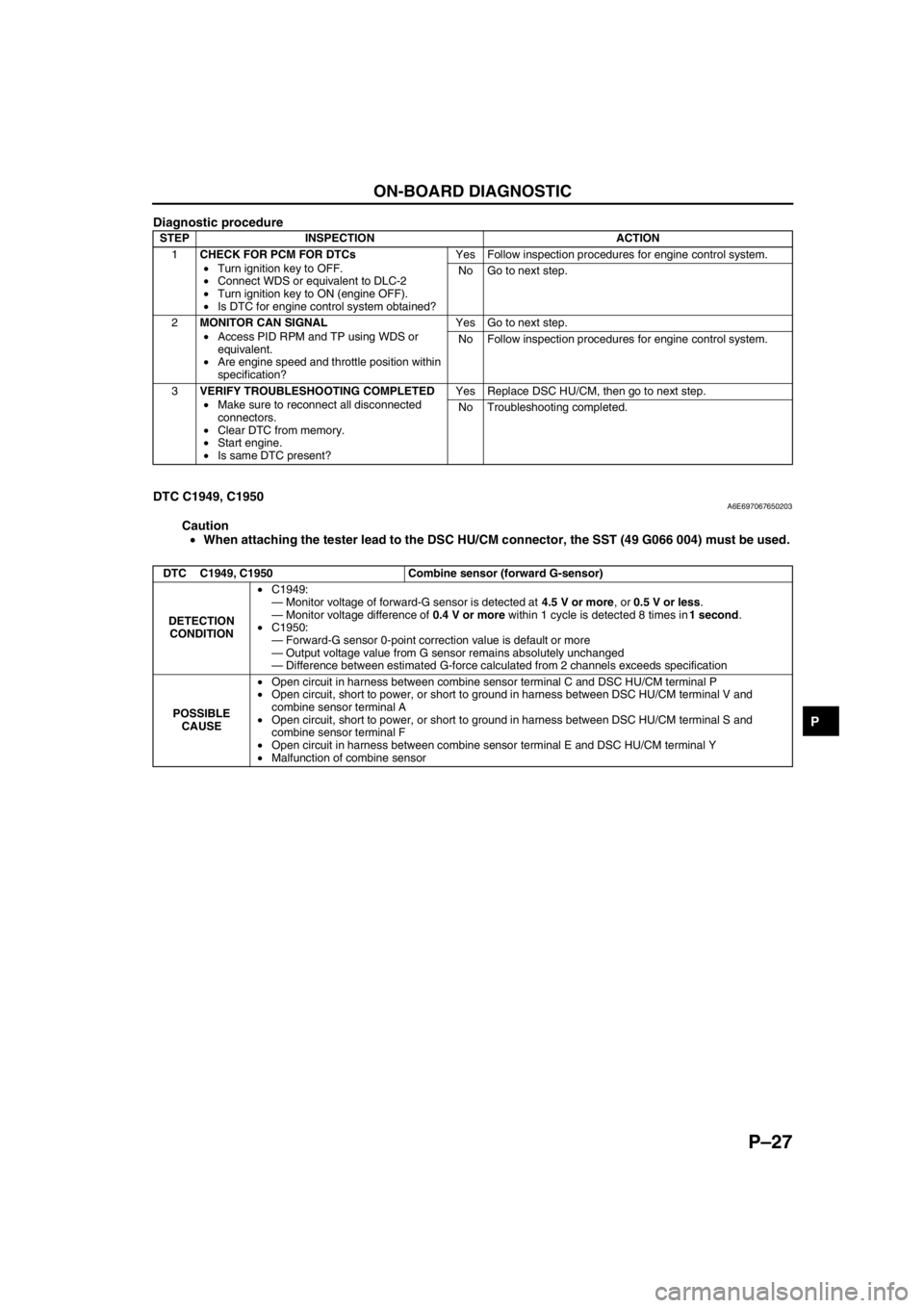
Diagnostic procedure
End Of Sie
DTC C1949, C1950A6E697067650203
Caution
•When attaching the tester lead to the DSC HU/CM connector, the SST (49 G066 004) must be used.
STEP INSPECTION ACTION
1CHECK FOR PCM FOR DTCs
•Turn ignition key to OFF.
•Connect WDS or equivalent to DLC-2
•Turn ignition key to ON (engine OFF).
•Is DTC for engine control system obtained?Yes Follow inspection procedures for engine control system.
No Go to next step.
2MONITOR CAN SIGNAL
•Access PID RPM and TP using WDS or
equivalent.
•Are engine speed and throttle position within
specification?Yes Go to next step.
No Follow inspection procedures for engine control system.
3VERIFY TROUBLESHOOTING COMPLETED
•Make sure to reconnect all disconnected
connectors.
•Clear DTC from memory.
•Start engine.
•Is same DTC present?Yes Replace DSC HU/CM, then go to next step.
No Troubleshooting completed.
DTC C1949, C1950 Combine sensor (forward G-sensor)
DETECTION
CONDITION•C1949:
—Monitor voltage of forward-G sensor is detected at 4.5 V or more, or 0.5 V or less.
—Monitor voltage difference of 0.4 V or more within 1 cycle is detected 8 times in 1 second.
•C1950:
—Forward-G sensor 0-point correction value is default or more
—Output voltage value from G sensor remains absolutely unchanged
—Difference between estimated G-force calculated from 2 channels exceeds specification
POSSIBLE
CAUSE•Open circuit in harness between combine sensor terminal C and DSC HU/CM terminal P
•Open circuit, short to power, or short to ground in harness between DSC HU/CM terminal V and
combine sensor terminal A
•Open circuit, short to power, or short to ground in harness between DSC HU/CM terminal S and
combine sensor terminal F
•Open circuit in harness between combine sensor terminal E and DSC HU/CM terminal Y
•Malfunction of combine sensor
Page 761 of 909
P–28
ON-BOARD DIAGNOSTIC
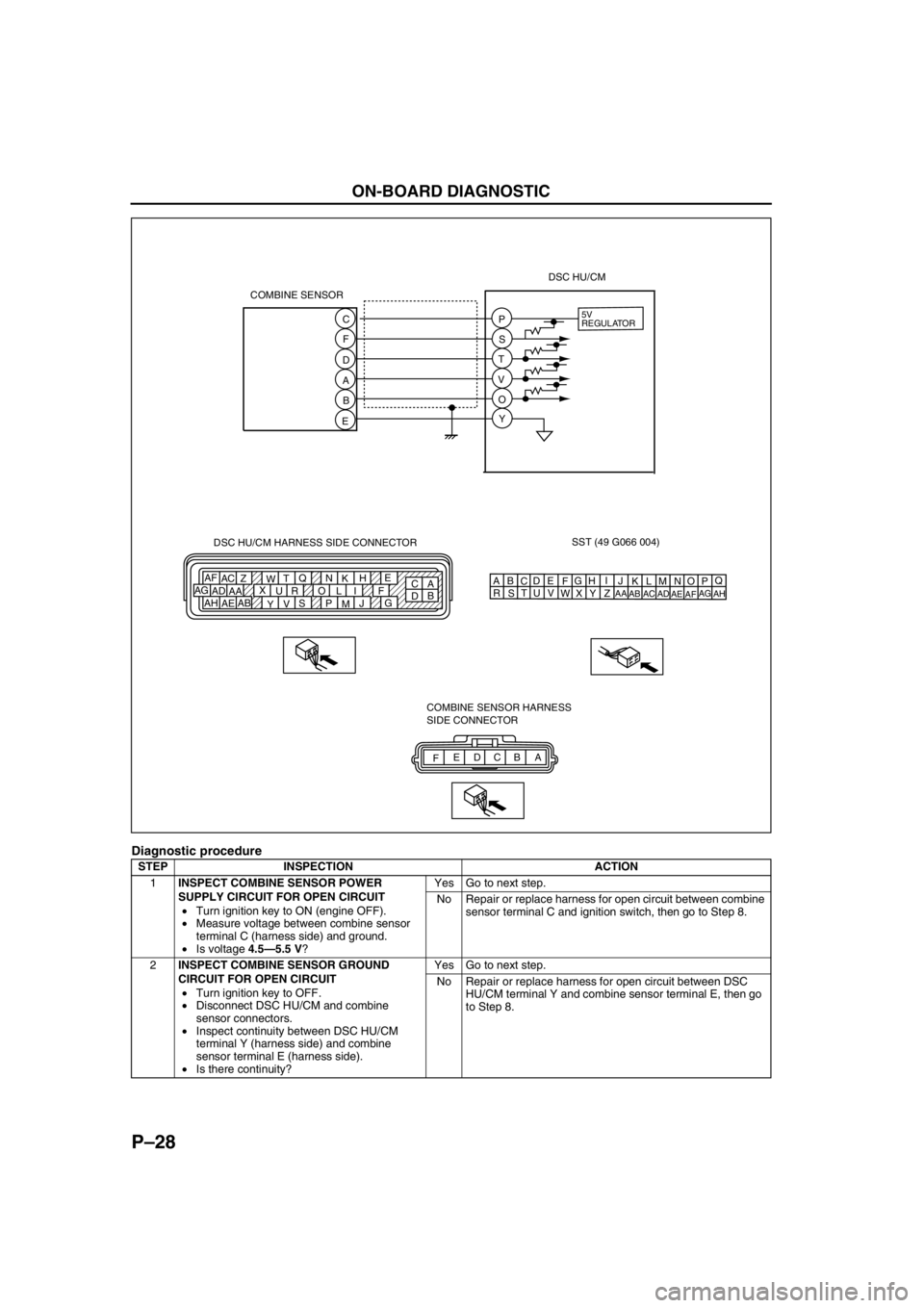
Diagnostic procedure
STEP INSPECTION ACTION
1INSPECT COMBINE SENSOR POWER
SUPPLY CIRCUIT FOR OPEN CIRCUIT
•Turn ignition key to ON (engine OFF).
•Measure voltage between combine sensor
terminal C (harness side) and ground.
•Is voltage 4.5—5.5 V?Yes Go to next step.
No Repair or replace harness for open circuit between combine
sensor terminal C and ignition switch, then go to Step 8.
2INSPECT COMBINE SENSOR GROUND
CIRCUIT FOR OPEN CIRCUIT
•Turn ignition key to OFF.
•Disconnect DSC HU/CM and combine
sensor connectors.
•Inspect continuity between DSC HU/CM
terminal Y (harness side) and combine
sensor terminal E (harness side).
•Is there continuity?Yes Go to next step.
No Repair or replace harness for open circuit between DSC
HU/CM terminal Y and combine sensor terminal E, then go
to Step 8.
SST (49 G066 004)
AQ
B
CDE
FG
HI
J DSC HU/CM HARNESS SIDE CONNECTOR
A
C E
H
K N Q
T
W Z AC AF
F I L O R U X
AA AD AG
G
J
M P S
V
Y AB
AE AHB
DKN
T
WZ
AC
AFLO
RU
XAA
ADAGMP
SV
YAB
AEAH 5V
REGULATOR
COMBINE SENSOR
FA B C D E COMBINE SENSOR HARNESS
SIDE CONNECTOR C
F
D
A
B
EP
S
T
V
O
YDSC HU/CM
Page 762 of 909
ON-BOARD DIAGNOSTIC
P–29
PEnd Of Sie
DTC U2511A6E697067650204
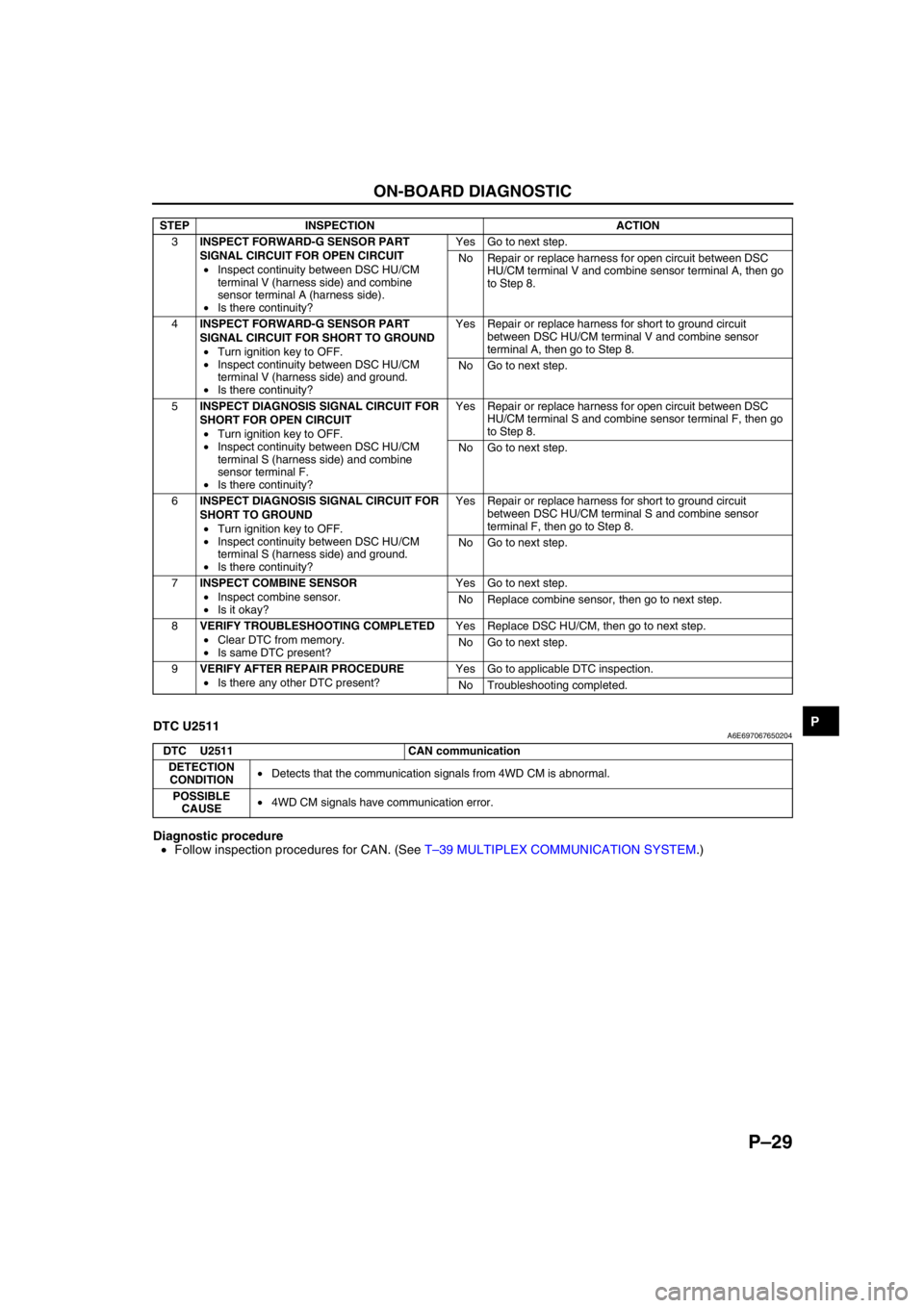
Diagnostic procedure
•Follow inspection procedures for CAN. (See T–39 MULTIPLEX COMMUNICATION SYSTEM.)
End Of Sie
3INSPECT FORWARD-G SENSOR PART
SIGNAL CIRCUIT FOR OPEN CIRCUIT
•Inspect continuity between DSC HU/CM
terminal V (harness side) and combine
sensor terminal A (harness side).
•Is there continuity?Yes Go to next step.
No Repair or replace harness for open circuit between DSC
HU/CM terminal V and combine sensor terminal A, then go
to Step 8.
4INSPECT FORWARD-G SENSOR PART
SIGNAL CIRCUIT FOR SHORT TO GROUND
•Turn ignition key to OFF.
•Inspect continuity between DSC HU/CM
terminal V (harness side) and ground.
•Is there continuity?Yes Repair or replace harness for short to ground circuit
between DSC HU/CM terminal V and combine sensor
terminal A, then go to Step 8.
No Go to next step.
5INSPECT DIAGNOSIS SIGNAL CIRCUIT FOR
SHORT FOR OPEN CIRCUIT
•Turn ignition key to OFF.
•Inspect continuity between DSC HU/CM
terminal S (harness side) and combine
sensor terminal F.
•Is there continuity?Yes Repair or replace harness for open circuit between DSC
HU/CM terminal S and combine sensor terminal F, then go
to Step 8.
No Go to next step.
6INSPECT DIAGNOSIS SIGNAL CIRCUIT FOR
SHORT TO GROUND
•Turn ignition key to OFF.
•Inspect continuity between DSC HU/CM
terminal S (harness side) and ground.
•Is there continuity?Yes Repair or replace harness for short to ground circuit
between DSC HU/CM terminal S and combine sensor
terminal F, then go to Step 8.
No Go to next step.
7INSPECT COMBINE SENSOR
•Inspect combine sensor.
•Is it okay?Yes Go to next step.
No Replace combine sensor, then go to next step.
8VERIFY TROUBLESHOOTING COMPLETED
•Clear DTC from memory.
•Is same DTC present?Yes Replace DSC HU/CM, then go to next step.
No Go to next step.
9VERIFY AFTER REPAIR PROCEDURE
•Is there any other DTC present?Yes Go to applicable DTC inspection.
No Troubleshooting completed. STEP INSPECTION ACTION
DTC U2511 CAN communication
DETECTION
CONDITION•Detects that the communication signals from 4WD CM is abnormal.
POSSIBLE
CAUSE•4WD CM signals have communication error.
Page 844 of 909
AIR BAG SYSTEM
T–33
T
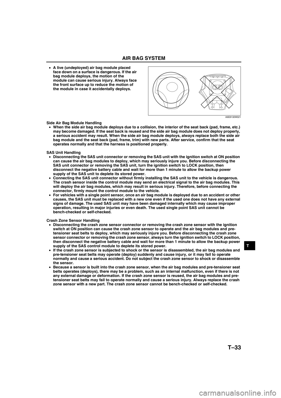
•A live (undeployed) air bag module placed
face down on a surface is dangerous. If the air
bag module deploys, the motion of the
module can cause serious injury. Always face
the front surface up to reduce the motion of
the module in case it accidentally deploys.
Side Air Bag Module Handling
•When the side air bag module deploys due to a collision, the interior of the seat back (pad, frame, etc.)
may become damaged. If the seat back is reused and the side air bag module does not deploy properly,
a serious accident may result. When the side air bag module deploys, always replace both the side air
bag module and the seat back (pad, frame, trim) with new parts. After service, confirm that the seat
operates normally and that the harness is positioned properly.
SAS Unit Handling
•Disconnecting the SAS unit connector or removing the SAS unit with the ignition switch at ON position
can cause the air bag modules to deploy, which may seriously injure you. Before disconnecting the
SAS unit connector or removing the SAS unit, turn the ignition switch to LOCK position, then
disconnect the negative battery cable and wait for more than 1 minute to allow the backup power
supply of the SAS unit to deplete its stored power.
•Connecting the SAS unit connector without firmly installing the SAS unit to the vehicle is dangerous.
The crash sensor inside the control module may send an electrical signal to the air bag modules. This
will deploy the air bag modules, which may result in serious injury. Therefore, before connecting the
connector, firmly mount the control module to the vehicle.
•For vehicles with a single point sensor, once an air bag module is deployed due to an accident or other
causes, the SAS unit must be replaced with a new one even if the used one does not have any external
signs of damage. The used SAS unit may have been damaged internally which may cause improper
operation, resulting in major injuries or even death. The used single point SAS unit cannot be
bench-checked or self-checked.
Crash Zone Sensor Handling
•Disconnecting the crash zone sensor connector or removing the crash zone sensor with the ignition
switch at ON position can cause the crash zone sensor to operate and the air bag modules and pre-
tensioner seat belts to deploy, which may seriously injure you. Before disconnecting the crash zone
sensor connector or removing the crash zone sensor, always turn the ignition switch to LOCK position,
then disconnect the negative battery cable and wait for more than 1 minute to allow the backup power
supply of the SAS control module to deplete its stored power.
•If the crash zone sensor is subjected to shock or the sensor is disassembled, the air bag modules and
pre-tensioner seat belts may operate (deploy) suddenly and cause injury, or it may fail to operate
normally and cause a serious accident. Do not subject the crash zone sensor to shock or disassemble
the sensor.
•Because a sensor is built into the crash zone sensor, when the air bag modules and pre-tensioner seat
belts operates (deploys), there may be a problem, such as an internal malfunction, even if there is not
any external damage or deformation. If the crash zone sensor is reused, the air bag modules and pre-
tensioner seat belts may fail to operate normally and cause a serious injury. Always replace the crash
zone sensor with a new part. The crash zone sensor cannot be bench-checked or self-checked.
A6E8130W021
Page 845 of 909

T–34
AIR BAG SYSTEM
Side Air Bag Sensor Handling
•Disconnecting the side air bag sensor connector or removing the side air bag sensor with the ignition
switch at ON position can cause the side air bag sensor to operate and the side air bag module to
deploy, which may seriously injure you. Before disconnecting the side air bag sensor connector or
removing the side air bag sensor, always turn the ignition switch to LOCK position, then disconnect the
negative battery cable and wait for more than 1 minute to allow the backup power supply of the SAS
control module to deplete its stored power.
•If the side air bag sensor is subjected to shock or the sensor is disassembled, the side air bag module
may operate (deploy) suddenly and cause injury, or it may fail to operate normally and cause a serious
accident. Do not subject the side air bag sensor to shock or disassemble the sensor.
•Because a sensor is built into the side air bag sensor, when the side air bag module operates (deploys),
there may be a problem, such as an internal malfunction, even if there is not any external damage or
deformation. If the side air bag sensor is reused, the side air bag module may fail to operate normally
and cause a serious injury. Always replace the side air bag sensor with a new part. The side air bag
sensor cannot be bench-checked or self-checked.
Pre-tensioner Seat Belt Inspection
•Inspecting a pre-tensioner seat belt using an
ohmmeter can deploy the pre-tensioner seat
belt, which can cause serious injury. Do not
use an ohmmeter to inspect the pre-tensioner
seat belt. Always use the on-board diagnostic
to diagnose the pre-tensioner seat belt for
malfunctions.
Component Handling
•Oil, grease, water, etc on components may cause the air bag modules and pre-tensioner seat belts to
fall to deploy in an accident, which may cause serious injury. Do not allow oil, grease, water, etc., on
components.
•Inserting a screwdriver, etc., into the
connector of an air bag module or a pre-
tensioner seat belt may damage the connector
and cause the air bag module or the pre-
tensioner seat belt to deploy improperly,
which may cause serious injury. Do not insert
any foreign objects into the connector.
Component Reuse
•Even if an air bag module or a pre-tensioner seat belt does not deploy in a collision and does not have
any external signs of damage, it may have been damaged internally, which may cause improper
operation. Improper operation may cause serious injury. Always self-check the undamaged air bag
module or pre-tensioner seat belt to determine whether it can be reused.
End Of Sie
A6E8130W025
A6E8130W023
Page 846 of 909
AIR BAG SYSTEM
T–35
T
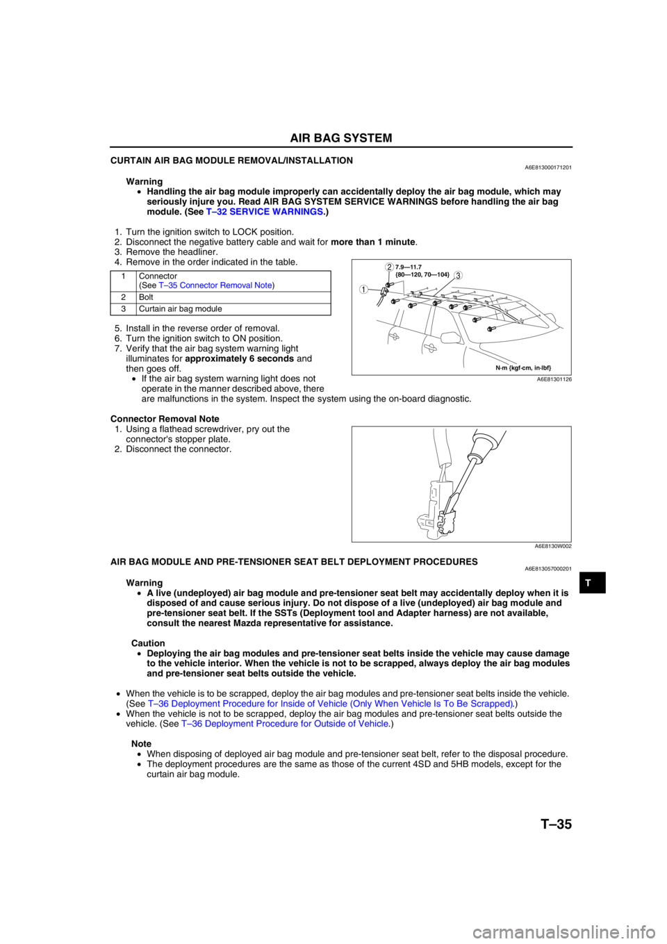
CURTAIN AIR BAG MODULE REMOVAL/INSTALLATIONA6E813000171201
Warning
•Handling the air bag module improperly can accidentally deploy the air bag module, which may
seriously injure you. Read AIR BAG SYSTEM SERVICE WARNINGS before handling the air bag
module. (See T–32 SERVICE WARNINGS.)
1. Turn the ignition switch to LOCK position.
2. Disconnect the negative battery cable and wait for more than 1 minute.
3. Remove the headliner.
4. Remove in the order indicated in the table.
5. Install in the reverse order of removal.
6. Turn the ignition switch to ON position.
7. Verify that the air bag system warning light
illuminates for approximately 6 seconds and
then goes off.
•If the air bag system warning light does not
operate in the manner described above, there
are malfunctions in the system. Inspect the system using the on-board diagnostic.
Connector Removal Note
1. Using a flathead screwdriver, pry out the
connector's stopper plate.
2. Disconnect the connector.
End Of SieAIR BAG MODULE AND PRE-TENSIONER SEAT BELT DEPLOYMENT PROCEDURESA6E813057000201
Warning
•A live (undeployed) air bag module and pre-tensioner seat belt may accidentally deploy when it is
disposed of and cause serious injury. Do not dispose of a live (undeployed) air bag module and
pre-tensioner seat belt. If the SSTs (Deployment tool and Adapter harness) are not available,
consult the nearest Mazda representative for assistance.
Caution
•Deploying the air bag modules and pre-tensioner seat belts inside the vehicle may cause damage
to the vehicle interior. When the vehicle is not to be scrapped, always deploy the air bag modules
and pre-tensioner seat belts outside the vehicle.
•When the vehicle is to be scrapped, deploy the air bag modules and pre-tensioner seat belts inside the vehicle.
(See T–36 Deployment Procedure for Inside of Vehicle (Only When Vehicle Is To Be Scrapped).)
•When the vehicle is not to be scrapped, deploy the air bag modules and pre-tensioner seat belts outside the
vehicle. (See T–36 Deployment Procedure for Outside of Vehicle.)
Note
•When disposing of deployed air bag module and pre-tensioner seat belt, refer to the disposal procedure.
•The deployment procedures are the same as those of the current 4SD and 5HB models, except for the
curtain air bag module.
1 Connector
(See T–35 Connector Removal Note)
2Bolt
3 Curtain air bag module3
1
2
N·m {kgf·cm, in·lbf} 7.9—11.7
{80—120, 70—104}
A6E81301126
A6E8130W002
Page 847 of 909

T–36
AIR BAG SYSTEM
Deployment Procedure for Inside of Vehicle (Only When Vehicle Is To Be Scrapped)
1. Inspect the SST (Deployment tool).
2. Move the vehicle to an open space, away from strong winds, and close all the doors and windows.
3. Turn the ignition switch to LOCK position.
4. Disconnect the negative battery cable and wait for more than 1 minute.
5. Follow the appropriate procedure for deploying the driver-side air bag module, passenger-side air bag module,
side air bag module, curtain air bag module, or pre-tensioner seat belt.
Curtain air bag module (WGN)
1. Remove the headliner.
2. Disconnect the curtain air bag module connector.
3. Connect the SST (Adapter harness) to the curtain
air bag module.
4. Connect the SST (Deployment tool) to the SST
(Adapter harness).
5. Connect the red clip of the SST (Deployment tool)
to the positive battery terminal and the black clip
to the negative battery terminal.
6. Verify that the red light on the SST (Deployment
tool) is illuminated.
7. Make sure all persons are standing at least 6 m
{20 ft} from the vehicle.
8. Press the activation switch on the SST
(Deployment tool) to deploy the curtain air bag
module.
Deployment Procedure for Outside of Vehicle
1. Inspect the SST (Deployment tool).
2. Turn the ignition switch to LOCK position.
3. Disconnect the negative battery cable and wait for more than 1 minute.
4. Follow the appropriate procedure for deploying the driver-side air bag module, passenger-side air bag module,
side air bag module, curtain air bag module, or pre-tensioner seat belt.
49 L066 002
CURTAIN
AIR BAG MODULE
CONNECTOR
A6E81301112
49 L066 002
49 H066 002
A6E8130W151
49 H066 002
ACTIVATION
SWITCH
A6E8130W028
Page 851 of 909
![MAZDA 6 2002 Workshop Manual Suplement T–40
ON-BOARD DIAGNOSTIC [MULTIPLEX COMMUNICATION SYSTEM]
Flowchart
•Use the following flowchart to verify the cause of the trouble.
End Of Sie
Repair the malfunctioning part by
following the DT MAZDA 6 2002 Workshop Manual Suplement T–40
ON-BOARD DIAGNOSTIC [MULTIPLEX COMMUNICATION SYSTEM]
Flowchart
•Use the following flowchart to verify the cause of the trouble.
End Of Sie
Repair the malfunctioning part by
following the DT](/img/28/57057/w960_57057-850.png)
T–40
ON-BOARD DIAGNOSTIC [MULTIPLEX COMMUNICATION SYSTEM]
Flowchart
•Use the following flowchart to verify the cause of the trouble.
End Of Sie
Repair the malfunctioning part by
following the DTC inspection.A
Inspect the power supply and the ground circuits for any units
that do not respond.
Are they normal?
Repair the malfunctioning part.A
A
B START
Using the SST (WDS or equivalent), verify if DTCs are displayed for PCM, TCM, ABS (ABS/TCS) HU/CM (with ABS (ABS/TCS)),
DSC HU/CM (with DSC), 4WD control module and instrument cluster.
Are any DTCs displayed?
Ye s
Are any DTCs other than the following displayed?
PCM: U0073, U0101, U0121, U0155
TCM: U0073, U0100
ABS (ABS/TCS) HU/CM, DSC HU/CM,
Instrument cluster: U1900, U2516
4WD control module: U0100, U0101, U0121
NoEND No
No Ye s
Are any of the following DTCs displayed?
PCM: U0073, U0101, U0121, U0155
TCM: U0073, U0100
ABS (ABS/TCS) HU/CM, DSC HU/CM,
Instrument cluster: U1900, U2516
4WD control module: U0100, U0101, U0121
Ye s
Ye s Narrow down CAN system malfunction location.
Using the SST (WDS or equivalent), verify if DTCs are displayed
for PCM, TCM, ABS (ABS/TCS) HU/CM, DSC HU/CM, 4WD
control module and instrument cluster.
Are any DTCs displayed?
No
Using the SST (WDS or equivalent), clear DTCs stored in
each module.
END
Ye s
No
Turn the ignition switch to the LOCK position.
Inspect the wiring harness and connector between
any unit that does not respond and the DLC-2.
PCM
—DLC-2 (except MZR-CD (RF Turbo))
2R—CAN_L
2U—CAN_H
PCM—DLC-2 (MZR-CD (RF Turbo))
39—CAN_L
13—CAN_H
TCM—DLC-2
2J—CAN_L
2M—CAN_H
ABS (ABS/TCS) HU/CM—DLC-2
X—KLN
DSC HU/CM—DLC-2
AB—KLN
4WD control module—DLC-2
H—CAN_L
G—CAN_H
Instrument cluster—DLC-2
2W—CAN_L
2X—CAN_H
Are the wiring harnesses and connectors normal? Is there a response from the PCM, TCM, ABS (ABS/TCS) HU/CM,
DSC HU/CM, 4WD control module and/or instrument cluster?
No Ye s
No
Ye s Repair the malfunctioning part by following the DTC inspection.
Repair the malfunctioning part.
A6E8162L101
Page 852 of 909
![MAZDA 6 2002 Workshop Manual Suplement ON-BOARD DIAGNOSTIC [MULTIPLEX COMMUNICATION SYSTEM]
T–40–1
T
T–40BODY ELECTRICAL SYSTEM
End Of Sie
ON-BOARD DIAGNOSTIC [MULTIPLEX COMMUNICATION SYSTEM]
Connect each unit connector.
Turn the ig MAZDA 6 2002 Workshop Manual Suplement ON-BOARD DIAGNOSTIC [MULTIPLEX COMMUNICATION SYSTEM]
T–40–1
T
T–40BODY ELECTRICAL SYSTEM
End Of Sie
ON-BOARD DIAGNOSTIC [MULTIPLEX COMMUNICATION SYSTEM]
Connect each unit connector.
Turn the ig](/img/28/57057/w960_57057-851.png)
ON-BOARD DIAGNOSTIC [MULTIPLEX COMMUNICATION SYSTEM]
T–40–1
T
T–40BODY ELECTRICAL SYSTEM
End Of Sie
ON-BOARD DIAGNOSTIC [MULTIPLEX COMMUNICATION SYSTEM]
Connect each unit connector.
Turn the ignition switch to the ON position.
Measure the voltage between DLC-2 terminals CAN_L and CAN_H.
Is the voltage 2.0—3.0 V?
Turn the ignition switch to the LOCK position.
Measure the resistance between DLC-2 terminals CAN_L and
CAN_H.
Is the resistance 59—65 ohms?
Replace any units that
do not respond.Disconnect the PCM connector.
Measure the resistance between PCM
connector terminals 2R and 2U
(except MZR-CD (RF Turbo)) or 13 and
39 (MZR-CD (RF Turbo)).
Is the resistance 118—130 ohms?
Replace the PCM.
Disconnect the instrument cluster connector.
Measure the resistance between instrument cluster connector
terminals 2W and 2X.
Is the resistance 118—130 ohms?
Replace the instrument
cluster.Turn the ignition switch to the LOCK position.
Disconnect the connector of any unit that does not respond.
(If there are two or more units that do not respond,
disconnect only one of the units.)
Turn the ignition switch to the ON position.
Measure the voltage between DLC-2 terminals CAN_L and
CAN_H.
Is the voltage 2.0—3.0 V?
The disconnected unit or the
related wiring harness may
have a malfunction.
Replace the disconnected unit. Replace the related wiring harness.The disconnected
unit is normal.
Are all units that do not respond disconnected?
Inspect if the related wiring harnesses (CAN_L
and/or CAN_H) have been shorted (to power
supply or ground).
If a short is found, replace the related wiring
harness. Ye sNo B
A A A AA
A
Turn the ignition switch to the LOCK position.
Verify the continuity between the following connector terminals of any disconnected unit.
PCM connector (except MZR-CD (RF Turbo)): 2R (CAN_L)—other terminals,
2U (CAN_H)—other terminals
PCM connector (MZR-CD (RF Turbo)): 39 (CAN_L)—other terminals,
13 (CAN_H)—other terminals
TCM connector: 2J (CAN_L)—other terminals, 2M (CAN_H)—other terminals
ABS (ABS/TCS) HU/CM connector: R (CAN_L)—other terminals,
O (CAN_H)—other terminals
DSC HU/CM connector: AF (CAN_L)—other terminals, AG (CAN_H)—other terminals
4WD control module connector: H (CAN_L)—other terminals, G (CAN_H)—other terminals
Instrument cluster connector: 2W (CAN_L)—other terminals, 2X (CAN_H)—other terminals
Is there continuity?
Ye s
No
Ye s
No
Ye sNo
Ye sNo
Ye sNo
Ye sNo
A6E8162L102
Page 879 of 909
U–16
CONTROL SYSTEM
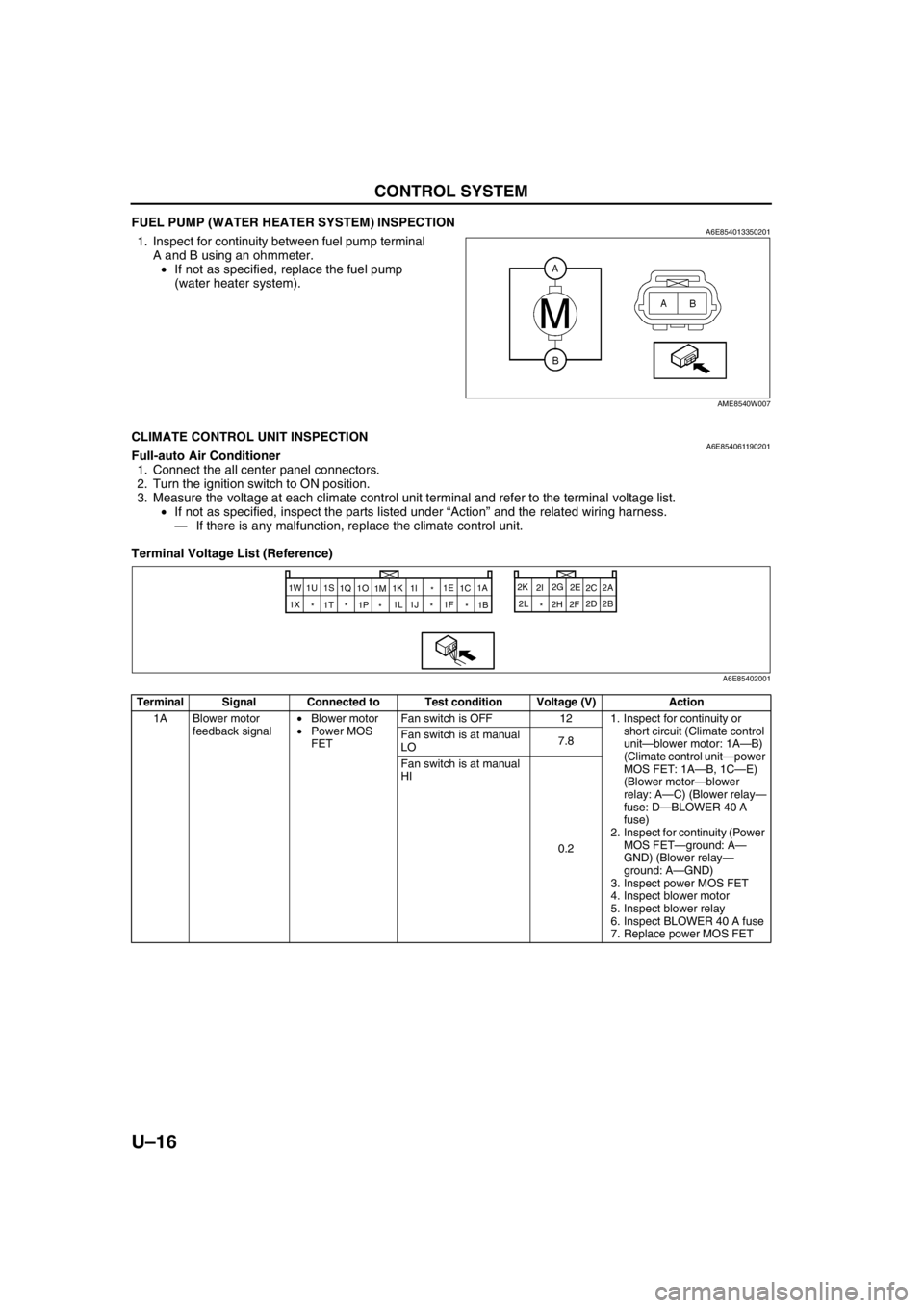
FUEL PUMP (WATER HEATER SYSTEM) INSPECTIONA6E8540133502011. Inspect for continuity between fuel pump terminal
A and B using an ohmmeter.
•If not as specified, replace the fuel pump
(water heater system).
End Of Sie
CLIMATE CONTROL UNIT INSPECTIONA6E854061190201Full-auto Air Conditioner
1. Connect the all center panel connectors.
2. Turn the ignition switch to ON position.
3. Measure the voltage at each climate control unit terminal and refer to the terminal voltage list.
•If not as specified, inspect the parts listed under “Action” and the related wiring harness.
—If there is any malfunction, replace the climate control unit.
Terminal Voltage List (Reference)
AME8540W007
Terminal Signal Connected to Test condition Voltage (V) Action
1A Blower motor
feedback signal•Blower motor
•Power MOS
FETFan switch is OFF 12 1. Inspect for continuity or
short circuit (Climate control
unit—blower motor: 1A—B)
(Climate control unit—power
MOS FET: 1A—B, 1C—E)
(Blower motor—blower
relay: A—C) (Blower relay—
fuse: D—BLOWER 40 A
fuse)
2. Inspect for continuity (Power
MOS FET—ground: A—
GND) (Blower relay—
ground: A—GND)
3. Inspect power MOS FET
4. Inspect blower motor
5. Inspect blower relay
6. Inspect BLOWER 40 A fuse
7. Replace power MOS FET Fan switch is at manual
LO7.8
Fan switch is at manual
HI
0.2
2A
1W
2B 2C
2D 2E
2F 2G
2H 2I 2K
2L
* 1A
1B
* *
* *
* 1X1C 1E
1F * 1I
1K
1M 1O
1P 1Q 1S
1T 1U
1J 1L
A6E85402001