belt MAZDA 6 2002 Suplement Owner's Guide
[x] Cancel search | Manufacturer: MAZDA, Model Year: 2002, Model line: 6, Model: MAZDA 6 2002Pages: 909, PDF Size: 17.16 MB
Page 234 of 909

F2–82
CONTROL SYSTEM
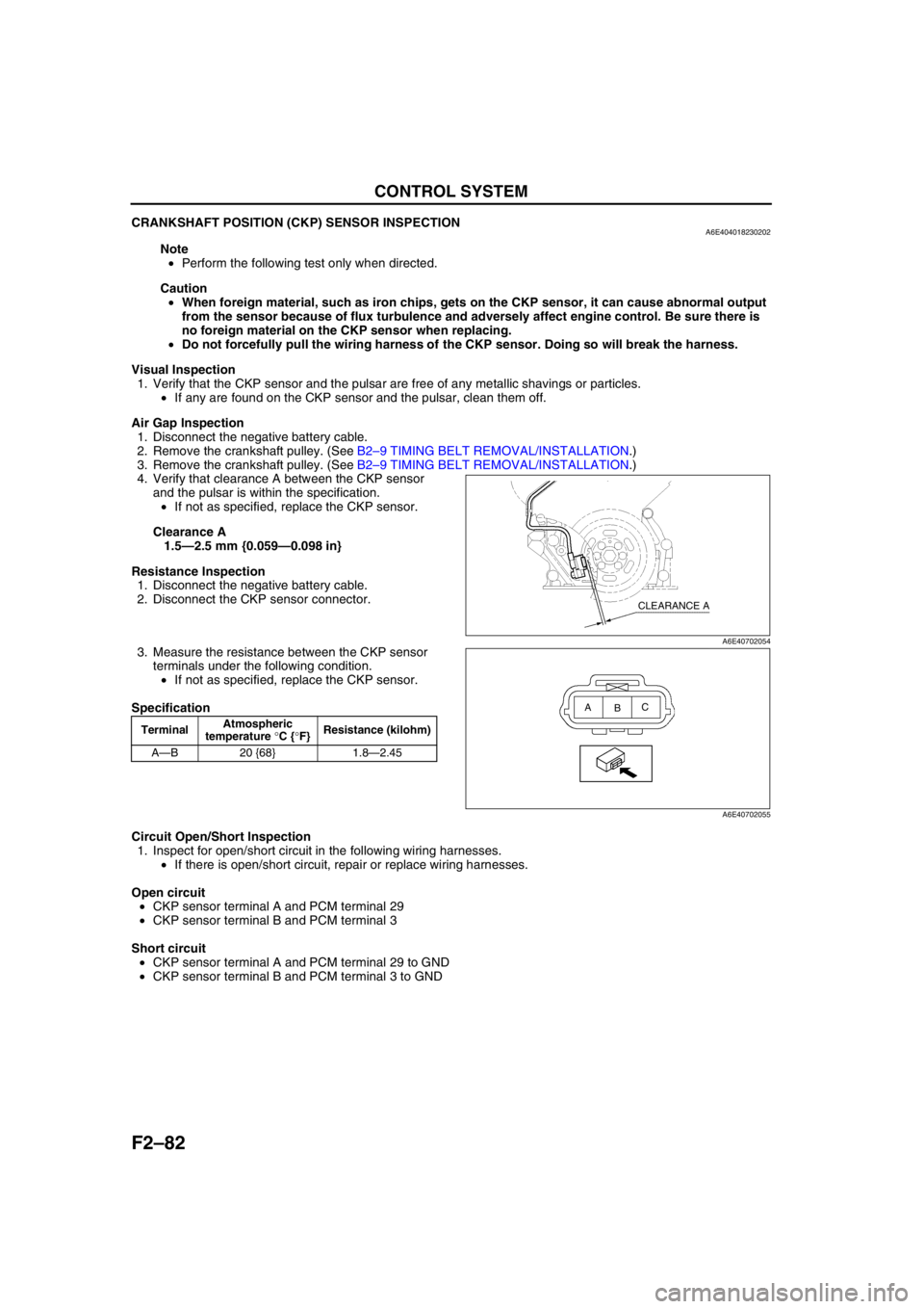
CRANKSHAFT POSITION (CKP) SENSOR INSPECTIONA6E404018230202
Note
•Perform the following test only when directed.
Caution
•When foreign material, such as iron chips, gets on the CKP sensor, it can cause abnormal output
from the sensor because of flux turbulence and adversely affect engine control. Be sure there is
no foreign material on the CKP sensor when replacing.
•Do not forcefully pull the wiring harness of the CKP sensor. Doing so will break the harness.
Visual Inspection
1. Verify that the CKP sensor and the pulsar are free of any metallic shavings or particles.
•If any are found on the CKP sensor and the pulsar, clean them off.
Air Gap Inspection
1. Disconnect the negative battery cable.
2. Remove the crankshaft pulley. (See B2–9 TIMING BELT REMOVAL/INSTALLATION.)
3. Remove the crankshaft pulley. (See B2–9 TIMING BELT REMOVAL/INSTALLATION.)
4. Verify that clearance A between the CKP sensor
and the pulsar is within the specification.
•If not as specified, replace the CKP sensor.
Clearance A
1.5—2.5 mm {0.059—0.098 in}
Resistance Inspection
1. Disconnect the negative battery cable.
2. Disconnect the CKP sensor connector.
3. Measure the resistance between the CKP sensor
terminals under the following condition.
•If not as specified, replace the CKP sensor.
Specification
Circuit Open/Short Inspection
1. Inspect for open/short circuit in the following wiring harnesses.
•If there is open/short circuit, repair or replace wiring harnesses.
Open circuit
•CKP sensor terminal A and PCM terminal 29
•CKP sensor terminal B and PCM terminal 3
Short circuit
•CKP sensor terminal A and PCM terminal 29 to GND
•CKP sensor terminal B and PCM terminal 3 to GND
End Of Sie
TerminalAtmospheric
temperature °C {°F}Resistance (kilohm)
A—B 20 {68} 1.8—2.45
CLEARANCE A
A6E40702054
A
BC
A6E40702055
Page 240 of 909

F2–88
ON-BOARD DIAGNOSTIC
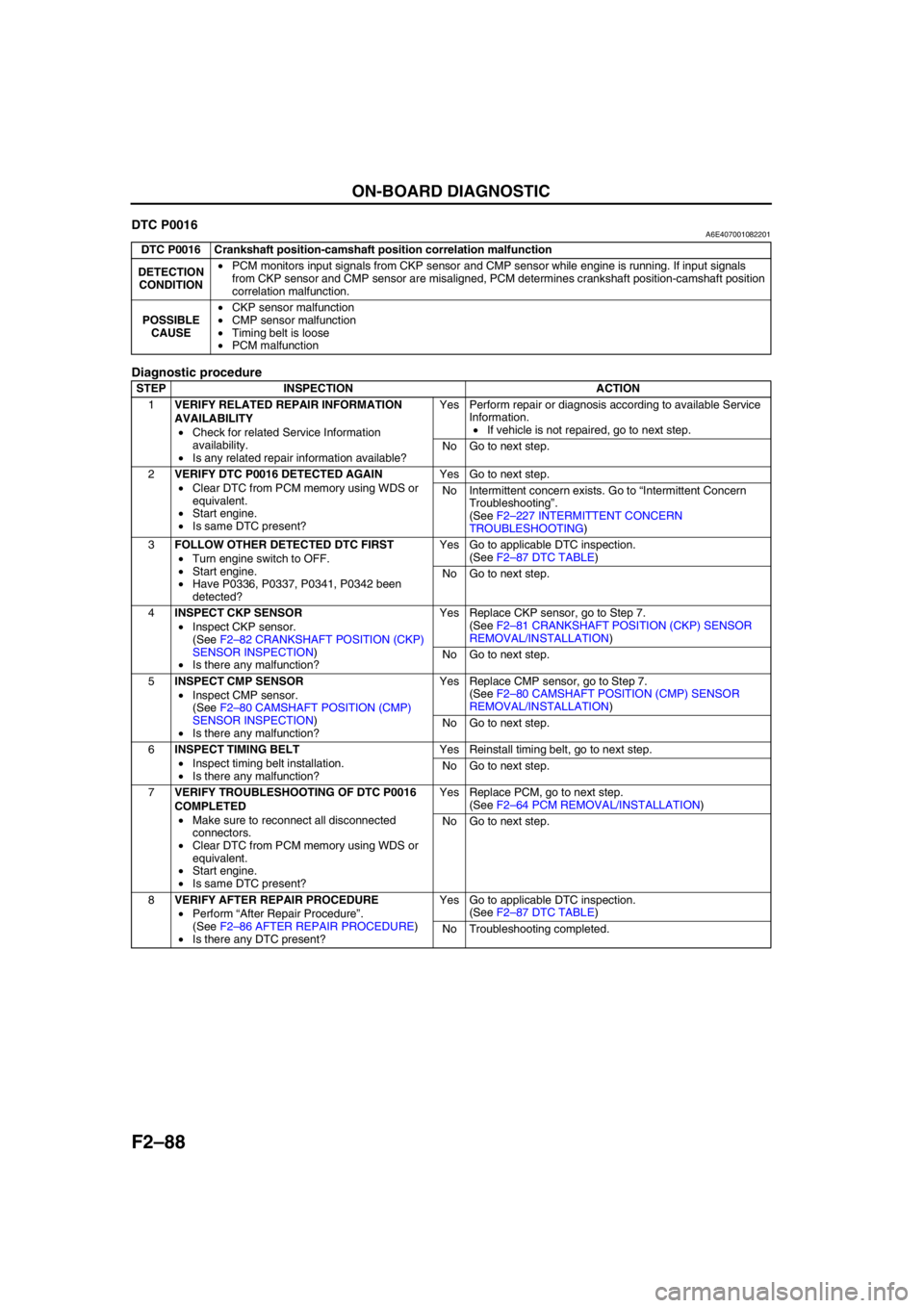
End Of SieDTC P0016A6E407001082201
Diagnostic procedure
End Of Sie
DTC P0016 Crankshaft position-camshaft position correlation malfunction
DETECTION
CONDITION•PCM monitors input signals from CKP sensor and CMP sensor while engine is running. If input signals
from CKP sensor and CMP sensor are misaligned, PCM determines crankshaft position-camshaft position
correlation malfunction.
POSSIBLE
CAUSE•CKP sensor malfunction
•CMP sensor malfunction
•Timing belt is loose
•PCM malfunction
STEP INSPECTION ACTION
1VERIFY RELATED REPAIR INFORMATION
AVAILABILITY
•Check for related Service Information
availability.
•Is any related repair information available?Yes Perform repair or diagnosis according to available Service
Information.
•If vehicle is not repaired, go to next step.
No Go to next step.
2VERIFY DTC P0016 DETECTED AGAIN
•Clear DTC from PCM memory using WDS or
equivalent.
•Start engine.
•Is same DTC present?Yes Go to next step.
No Intermittent concern exists. Go to “Intermittent Concern
Troubleshooting”.
(See F2–227 INTERMITTENT CONCERN
TROUBLESHOOTING)
3FOLLOW OTHER DETECTED DTC FIRST
•Turn engine switch to OFF.
•Start engine.
•Have P0336, P0337, P0341, P0342 been
detected?Yes Go to applicable DTC inspection.
(See F2–87 DTC TABLE)
No Go to next step.
4INSPECT CKP SENSOR
•Inspect CKP sensor.
(See F2–82 CRANKSHAFT POSITION (CKP)
SENSOR INSPECTION)
•Is there any malfunction?Yes Replace CKP sensor, go to Step 7.
(See F2–81 CRANKSHAFT POSITION (CKP) SENSOR
REMOVAL/INSTALLATION)
No Go to next step.
5INSPECT CMP SENSOR
•Inspect CMP sensor.
(See F2–80 CAMSHAFT POSITION (CMP)
SENSOR INSPECTION)
•Is there any malfunction?Yes Replace CMP sensor, go to Step 7.
(See F2–80 CAMSHAFT POSITION (CMP) SENSOR
REMOVAL/INSTALLATION)
No Go to next step.
6INSPECT TIMING BELT
•Inspect timing belt installation.
•Is there any malfunction?Yes Reinstall timing belt, go to next step.
No Go to next step.
7VERIFY TROUBLESHOOTING OF DTC P0016
COMPLETED
•Make sure to reconnect all disconnected
connectors.
•Clear DTC from PCM memory using WDS or
equivalent.
•Start engine.
•Is same DTC present?Yes Replace PCM, go to next step.
(See F2–64 PCM REMOVAL/INSTALLATION)
No Go to next step.
8VERIFY AFTER REPAIR PROCEDURE
•Perform “After Repair Procedure”.
(See F2–86 AFTER REPAIR PROCEDURE)
•Is there any DTC present?Yes Go to applicable DTC inspection.
(See F2–87 DTC TABLE)
No Troubleshooting completed.
Page 319 of 909

TROUBLESHOOTING
F2–167
F2
SYMPTOM QUICK DIAGNOSIS CHARTA6E408018881202
×: Applicable
Troubleshooting item
1 Melting of main or other fuses
2 MIL illuminates
3 Will not crank×× ×× × ×
4 Hard start/long crank/erratic start/erratic crank×× ×
5 Engine stalls After start/at idle××
6 Cranks normally but will not start××
7 Slow return to idle
8 Engine runs rough/rolling idle××
9 Fast idle/runs on
10 Low idle/stalls during deceleration××
11Engine stalls/quits Acceleration/cruise××
Engine runs rough Acceleration/cruise××
Misses Acceleration/cruise××
Buck/jerk Acceleration/cruise/ deceleration××
Hesitation/stumble Acceleration××
Surges Acceleration/cruise××
12 Lack/loss of power Acceleration/cruise××
13 Knocking/pinging××
14 Poor fuel economy××
15 Emissions compliance×× ×
16 High oil consumption/leakage××××
17 Cooling system concerns Overheating××
18 Cooling system concerns Runs cold
19 Excessive black smoke×
20 Fuel odor (in engine compartment)
21 Engine noise×× × ×
22 Vibration concerns (engine)×
23 A/C does not work sufficiently
24 A/C always on or A/C compressor runs continuously
25 A/C does not cut off under wide open throttle conditions
26 Constant voltage
Starter motor malfunction (Mechanical or electrical)Starter circuit including engine switch is openImproper engine oil levelLow or dead bateryCharging system malfunctionLow engine compressionImproper valve timingHydrolocked egineImproper engine oil viscosityImproper dipstickBase engine malfunctionSeized flywheelImproper tension or damaged drivebelts
Page 346 of 909

F2–194
TROUBLESHOOTING
End Of Sie
11 Inspect adjustment of accelerator position
sensor and idle switch.
(See F2–72 ACCELERATOR POSITION
SENSOR INSPECTION)
(See F2–70 IDLE SWITCH INSPECTION)
Are accelerator position sensor and idle switch
adjusted correctly?Yes Go to next step.
No Adjust accelerator position sensor and idle switch
correctly.
(See F2–73 ACCELERATOR POSITION SENSOR
ADJUSTMENT)
(See F2–71 IDLE SWITCH ADJUSTMENT)
12 Inspect adjustment of neutral switch.
(See F2–69 NEUTRAL SWITCH INSPECTION)
Is neutral switch adjusted correctly?Yes Go to next step.
No Adjust neutral switch correctly.
13 Visually inspect CKP sensor and teeth of pulse
wheel.
Are CKP sensor and teeth of pulse wheel okay?Yes Go to next step.
No Replace malfunctioning parts.
14 Measure gap between CKP sensor and teeth of
pulse wheel.
Specification
1.5—2.5 mm {0.059—0.098 in}
Is gap within specification?Yes Go to next step.
No Adjust CKP sensor position.
15 Visually inspect CMP sensor and teeth of pulse
wheel.
Are CMP sensor and teeth of pulse wheel okay?Yes Inspect following PIDs:
(See F2–65 PCM INSPECTION)
•ECT
•IAT
•MAF
•RPM
If PID value is not as specified, repair or replace
malfunctioning parts.
If PID value is okay, go to next step.
No Replace malfunctioning parts.
16 Inspect fuel pressure sensor.
(See F2–79 FUEL PRESSURE SENSOR
INSPECTION)
Is fuel pressure okay?Yes Go to next step.
No Replace common rail.
17 Inspect suction control valve.
(See F2–54 SUCTION CONTROL VALVE
INSPECTION)
Is suction control valve okay?Yes Go to next step.
No Repair supply pump.
(See F2–54 SUPPLY PUMP INSPECTION)
18 Is engine compression correct?
(See B2–8 COMPRESSION INSPECTION)Yes Go to next step.
No Inspect for following:
•Damaged valve seat
•Worn valve stem and valve guide
•Worn or stuck piston ring
•Worn piston, piston ring or cylinder
•Improper valve timing
Service as necessary.
19 Inspect fuel injector.
(See F2–56 FUEL INJECTOR INSPECTION)
Is fuel injector okay?Yes Go to next step.
No Repair or replace as necessary.
20 Inspect IDM.
(See F2–84 INJECTOR DRIVER MODULE
(IDM) INSPECTION)
Is IDM okay?Yes Go to next step.
No Repair or replace as necessary.
21 Inspect timing belt for following:
•Chipping of gear teeth
•Low tension
•Breakage damage or cracks
Is timing belt okay?Yes Inspect following:
•Clutch slippage
•CKP sensor
•VSS
If okay, remove and inspect supply pump and common
rail.
No If timing is incorrect, adjust valve timing.
If timing belt is not okay, replace timing belt.
22 Verify test results.
•If okay, return to diagnostic index to service any additional symptoms.
•If malfunction remains, replace PCM. (See F2–64 PCM REMOVAL/INSTALLATION) STEP INSPECTION RESULTS ACTION
Page 350 of 909

F2–198
TROUBLESHOOTING
End Of Sie
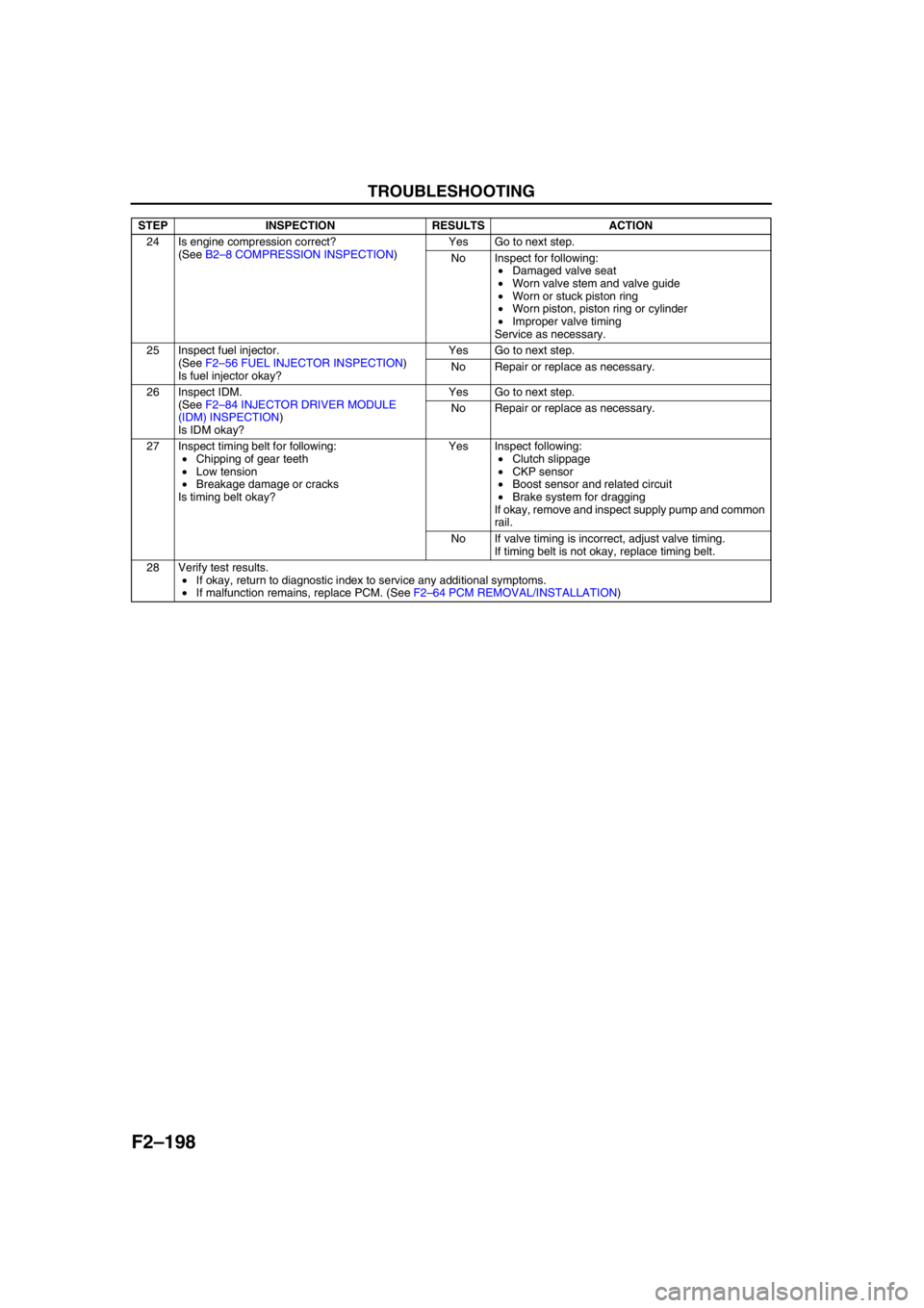
24 Is engine compression correct?
(See B2–8 COMPRESSION INSPECTION)Yes Go to next step.
No Inspect for following:
•Damaged valve seat
•Worn valve stem and valve guide
•Worn or stuck piston ring
•Worn piston, piston ring or cylinder
•Improper valve timing
Service as necessary.
25 Inspect fuel injector.
(See F2–56 FUEL INJECTOR INSPECTION)
Is fuel injector okay?Yes Go to next step.
No Repair or replace as necessary.
26 Inspect IDM.
(See F2–84 INJECTOR DRIVER MODULE
(IDM) INSPECTION)
Is IDM okay?Yes Go to next step.
No Repair or replace as necessary.
27 Inspect timing belt for following:
•Chipping of gear teeth
•Low tension
•Breakage damage or cracks
Is timing belt okay?Yes Inspect following:
•Clutch slippage
•CKP sensor
•Boost sensor and related circuit
•Brake system for dragging
If okay, remove and inspect supply pump and common
rail.
No If valve timing is incorrect, adjust valve timing.
If timing belt is not okay, replace timing belt.
28 Verify test results.
•If okay, return to diagnostic index to service any additional symptoms.
•If malfunction remains, replace PCM. (See F2–64 PCM REMOVAL/INSTALLATION) STEP INSPECTION RESULTS ACTION
Page 356 of 909

F2–204
TROUBLESHOOTING
End Of Sie
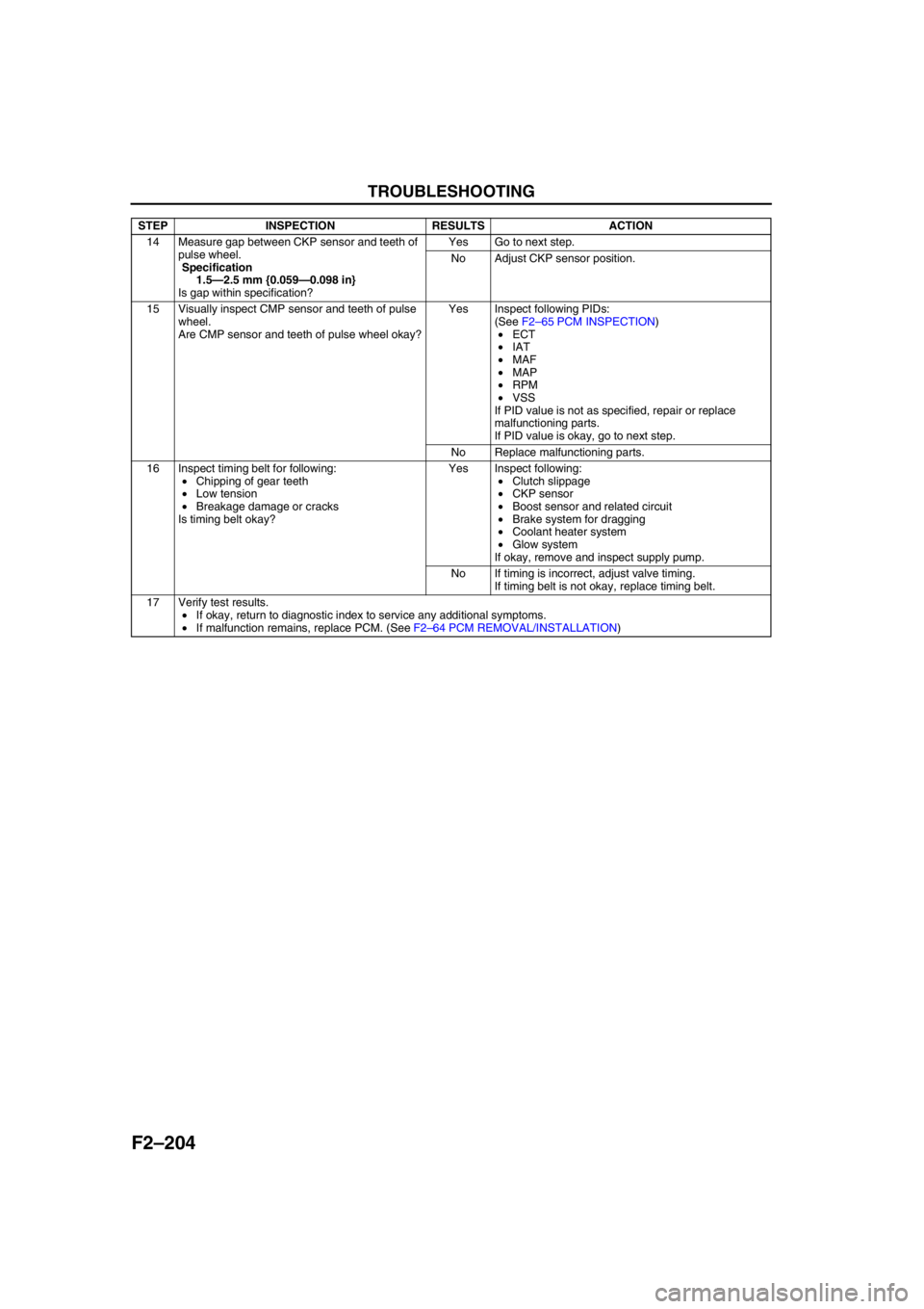
14 Measure gap between CKP sensor and teeth of
pulse wheel.
Specification
1.5—2.5 mm {0.059—0.098 in}
Is gap within specification?Yes Go to next step.
No Adjust CKP sensor position.
15 Visually inspect CMP sensor and teeth of pulse
wheel.
Are CMP sensor and teeth of pulse wheel okay?Yes Inspect following PIDs:
(See F2–65 PCM INSPECTION)
•ECT
•IAT
•MAF
•MAP
•RPM
•VSS
If PID value is not as specified, repair or replace
malfunctioning parts.
If PID value is okay, go to next step.
No Replace malfunctioning parts.
16 Inspect timing belt for following:
•Chipping of gear teeth
•Low tension
•Breakage damage or cracks
Is timing belt okay?Yes Inspect following:
•Clutch slippage
•CKP sensor
•Boost sensor and related circuit
•Brake system for dragging
•Coolant heater system
•Glow system
If okay, remove and inspect supply pump.
No If timing is incorrect, adjust valve timing.
If timing belt is not okay, replace timing belt.
17 Verify test results.
•If okay, return to diagnostic index to service any additional symptoms.
•If malfunction remains, replace PCM. (See F2–64 PCM REMOVAL/INSTALLATION) STEP INSPECTION RESULTS ACTION
Page 360 of 909

F2–208
TROUBLESHOOTING
End Of Sie
25 Is engine compression correct?
(See B2–8 COMPRESSION INSPECTION)Yes Go to next step.
No Inspect for following:
•Damaged valve seat
•Worn valve stem and valve guide
•Worn or stuck piston ring
•Worn piston, piston ring or cylinder
•Improper valve timing
Service as necessary.
26 Inspect fuel injector.
(See F2–56 FUEL INJECTOR INSPECTION)
Is fuel injector okay?Yes Go to next step.
No Repair or replace as necessary.
27 Inspect IDM.
(See F2–84 INJECTOR DRIVER MODULE
(IDM) INSPECTION)
Is IDM okay?Yes Go to next step.
No Repair or replace as necessary.
28 Inspect timing belt for followings:
•Chipping of gear teeth
•Low tension
•Breakage damage or cracks
Is timing belt okay?Yes Inspect following:
•ECT sensor
•Boost sensor
•MAF/IAT sensor
•Catalyst converter
If okay, remove and inspect supply pump and common
rail.
No If timing is incorrect, adjust valve timing.
If timing belt is not okay, replace timing belt.
29 Verify test results.
•If okay, return to diagnostic index to service any additional symptoms.
•If malfunction remains, replace PCM. (See F2–64 PCM REMOVAL/INSTALLATION) STEP INSPECTION RESULTS ACTION
Page 362 of 909

F2–210
TROUBLESHOOTING
End Of SieNO.17 COOLING SYSTEM CONCERNS-OVERHEATINGA6E408018881219
Diagnostic Procedure
17
COOLING SYSTEM CONCERNS-OVERHEATING
DESCRIPTION•Engine runs at higher than normal temperature/overheats.
POSSIBLE
CAUSE•Cooling fan No.2 malfunction
•Cooling fan No.1 malfunction
•Low drive belt tension
•Drive belt damage
•Improper coolant level
•Thermostat malfunction
•Radiator clogging
•Improper water/anti-freeze mixture
•Improper or damaged radiator cap
•Radiator hose damage
•Coolant leakage (engine internal, turbocharger, external)
•A/C system malfunction
•EGR system malfunction
•Coolant heater system malfunction
STEP INSPECTION RESULTS ACTION
1 Inspect following:
•Engine coolant level
•Coolant leakage (around heater unit in
passenger compartment, coolant hoses and/
or radiator, and around coolant heater unit.)
•Water and anti-freeze mixture
•Radiator condition
•Collapsed or restricted radiator hoses
•Radiator pressure cap
•Drive belt tension
•Drive belt
•Fan rotational direction
Are all items okay?Yes Go to next step.
No Service as necessary.
Repeat Step 1.
2 Perform self-test function using WDS or
equivalent.
Turn engine switch to ON.
Retrieve any DTC.
Is DTC displayed?YesDTC is displayed:
Go to appropriate DTC test.
Communication error message is displayed:
Inspect for following:
•Open circuit between PCM control relay and PCM
terminal 53 or 79
•Open circuit PCM control relay and PCM terminal
69
•PCM control relay stuck open
•Open or poor GND circuit (PCM terminal 65, 85,
103 or 104)
•Poor connection vehicle body GND
NoNo DTC is displayed:
Go to next step.
Page 363 of 909

TROUBLESHOOTING
F2–211
F2
End Of Sie
3Note
•The following test should be performed on
the vehicles with A/C system. Go to next
step for vehicles without A/C system
Start engine and run it at idle speed.
Turn A/C switch off.
Does A/C compressor disengaged?Yes Go to next step.
No Go to symptom troubleshooting “NO.24 A/C ALWAYS
ON OR A/C COMPRESSOR RUNS
CONTINUOUSLY”.
4 Start engine and run it at idle speed.
Turn A/C switch on if equipped.
Do cooling fan No.1 and/or cooling fan No.2
operate?Yes Go to next step.
NoCooling fan No.1 does not operate:
Inspect for following:
•Cooling fan relay No.1 is stuck open
•Cooling fan motor No.1 malfunction
•Cooling fan motor No.1 GND open
•Open circuit between cooling fan motor No.1 and
relay
•Open circuit between cooling fan relay No.1 and
PCM terminal 102
•Open battery power circuit of cooling fan relay
No.1
Cooling fan No.2 does not operate:
Inspect for following:
•Cooling fan relay No.2 is stuck open
•Cooling fan motor No.2 malfunction
•Cooling fan motor No.2 GND open
•Open circuit between Cooling fan motor No.2 and
relay
•Open circuit between Cooling fan relay No.2 and
PCM terminal 76
•Open battery power circuit of Cooling fan relay
No.2
5 Is drive belt okay? Yes Go to next step.
No Replace drive belt.
6 Perform EGR system inspection.
Is EGR system okay?Yes Go to next step.
No Repair or replace malfunctioning part according to
EGR system operation results.
7 Perform coolant heater system inspection.
(See E–10 THERMOSTAT INSPECTION)
Is coolant heater system okay?Yes Go to next step.
No Repair or replace malfunctioning part according to
coolant heater system operation results.
8 Cool down engine.
Remove thermostat and inspect operation.
Is thermostat okay?Yes Thermostat is okay.
Inspect cylinder block for leakage or blockage.
No Replace thermostat.
9 Verify test results.
•If okay, return to diagnostic index to service any additional symptoms.
•If malfunction remains, replace PCM. (See F2–64 PCM REMOVAL/INSTALLATION) STEP INSPECTION RESULTS ACTION
Page 369 of 909

TROUBLESHOOTING
F2–217
F2
NO.21 ENGINE NOISEA6E408018881223
Diagnostic Procedure
21 ENGINE NOISE
DESCRIPTION•Engine noise under hood.
POSSIBLE
CAUSE•Engine internal damage
•Timing belt displacement
•Fuel injector malfunction
•Loose attaching bolts or worn parts
•Improper drive belt tension
•Air leakage from intake-air system
•Incorrect injection timing
•Erratic signal from CKP sensor
•Erratic signal from CMP sensor
•Fuel pressure sensor or related circuit malfunction
•Boost sensor or related circuit malfunction
•Accelerator position sensor or related circuit malfunction
•MAF/IAT sensor or related circuit malfunction
•ECT sensor or related circuit malfunction
•EGR system or malfunction
•IAT sensor No.2 or related circuit malfunction
•Vacuum leakage
•Suction control valve malfunction (built-in supply pump)
•Air leakage from intake-air system
•Air in power steering fluid line
•Turbocharger operating noise
•Solenoid valve operating noise
Warning
The following troubleshooting flow chart contains the fuel system diagnosis and repair
procedures. Read the following warnings before performing the fuel system services:
•Fuel vapor is hazardous. It can easily ignite, causing serious injury and damage. Always keep
sparks and flames away from fuel.
•Fuel line spills and leakage are dangerous. Fuel can ignite and cause serious injury or death
and damage. Fuel can also irritate skin and eyes. To prevent this, always complete “BEFORE
REPAIR PROCEDURE” and “AFTER REPAIR PROCEDURE” described in this manual.
Note
•PCM checks fuel injection amount during a set interval while idling, and automatically corrects it to
maintain engine efficiency. It is normal that engine noise and vibration might be a little louder during
this process.
STEP INSPECTION RESULTS ACTION
1 Is squeal, click or chirp sound present? Yes Inspect engine oil level, solenoid valves installation or
drive belt.
No Go to next step.
2 Is rumble or grind sound present? Yes Inspect drive belt tension or power steering system
fluid level.
If okay, perform power steering fluid line air bleed.
No Go to next step.
3 Is rattle sound present? Yes Inspect location of rattle for loose parts.
No Go to next step.
4 Is hiss sound present? Yes Inspect for vacuum leakage and intake-air system
leakage.
No Go to next step.
5 Is rap or roar sound present? Yes Inspect exhaust system or loose parts.
No Go to next step.