belt MAZDA 6 2002 Suplement Service Manual
[x] Cancel search | Manufacturer: MAZDA, Model Year: 2002, Model line: 6, Model: MAZDA 6 2002Pages: 909, PDF Size: 17.16 MB
Page 372 of 909

F2–220
TROUBLESHOOTING
NO.22 VIBRATION CONCERNS (ENGINE)A6E408018881224
Diagnostic Procedure
22 VIBRATION CONCERNS (ENGINE)
DESCRIPTION•Vibration from under hood or driveline.
POSSIBLE
CAUSE•Loose attaching bolts or worn parts
•Cooling fan No.1 or cooling fan No.2 seat are improper
•Engine or transaxle mounts are improperly installed
•Components malfunction such as worn parts
•Erratic signal from CMP sensor
•ECT sensor or related circuit malfunction
•Accelerator position sensor or related circuit malfunction
•MAF/IAT sensor or related circuit malfunction
•Idle switch or related circuit malfunction
•Incorrect adjustment of accelerator position sensor and/or idle switch
•Fuel injector malfunction
•Vacuum leakage
•Improper tension or damaged drive belts
•Improper balance of wheels or tires
•Driveline malfunction
•Suspension malfunction
Warning
The following troubleshooting flow chart contains the fuel system diagnosis and repair
procedures. Read the following warnings before performing the fuel system services:
•Fuel vapor is hazardous. It can easily ignite, causing serious injury and damage. Always keep
sparks and flames away from fuel.
•Fuel line spills and leakage are dangerous. Fuel can ignite and cause serious injury or death
and damage. Fuel can also irritate skin and eyes. To prevent this, always complete “BEFORE
REPAIR PROCEDURE” and “AFTER REPAIR PROCEDURE” described in this manual.
STEP INSPECTION RESULTS ACTION
1 Inspect following components for loose attaching
bolts or worn parts:
•Cooling fan No.1
•Cooling fan No.2
•Cooling fan No.1 and cooling fan No.2 seat
•Drive belt and pulley
•Engine mounts
•Exhaust system
Are all items okay?Yes Go to next step.
No Readjust or retighten engine mount installation
position.
Service as necessary for other parts.
2 Inspect vacuum leakage.
Are vacuum hoses okay?Yes Go to next step.
No Service as necessary.
Repeat Step 2.
Page 390 of 909

CHARGING SYSTEM
G–7
G
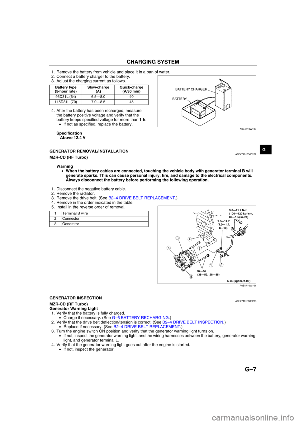
1. Remove the battery from vehicle and place it in a pan of water.
2. Connect a battery charger to the battery.
3. Adjust the charging current as follows.
4. After the battery has been recharged, measure
the battery positive voltage and verify that the
battery keeps specified voltage for more than 1 h.
•If not as specified, replace the battery.
Specification
Above 12.4 V
End Of Sie
GENERATOR REMOVAL/INSTALLATIONA6E471018300202MZR-CD (RF Turbo)
Warning
•When the battery cables are connected, touching the vehicle body with generator terminal B will
generate sparks. This can cause personal injury, fire, and damage to the electrical components.
Always disconnect the battery before performing the following operation.
1. Disconnect the negative battery cable.
2. Remove the radiator.
3. Remove the drive belt. (See B2–4 DRIVE BELT REPLACEMENT.)
4. Remove in the order indicated in the table.
5. Install in the reverse order of removal.
End Of SieGENERATOR INSPECTIONA6E471018300203MZR-CD (RF Turbo)
Generator Warning Light
1. Verify that the battery is fully charged.
•Charge if necessary. (See G–6 BATTERY RECHARGING.)
2. Verify that the drive belt deflection/tension is correct. (See B2–4 DRIVE BELT INSPECTION.)
•Replace if necessary. (See B2–4 DRIVE BELT REPLACEMENT.)
3. Turn the engine switch ON position and verify that the generator warning light turns on.
•If not, inspect the generator warning light, and the wiring harnesses between the battery, generator warning
light, and generator terminal L.
4. Verify that the generator warning light goes out after the engine is started.
•If not, inspect the generator.
Battery type
(5-hour rate)Slow-charge
(A)Quick-charge
(A/30 min)
95D31L (64) 6.5—8.0 40
115D31L (70) 7.0—8.5 45BATTERY CHARGER
BATTERY
A6E4710W100
1 Terminal B wire
2 Connector
3 Generator
3
12
A
B
A
B
9.8—14.7
{1.0—1.4,
8—10}
N·m {kgf·m, ft·lbf}
37—52
{38—53, 28—38}
9.8—11.7 N·m
{100—120 kgf·cm,
87—104 in·lbf}
A6E4710W101
Page 391 of 909

G–8
CHARGING SYSTEM
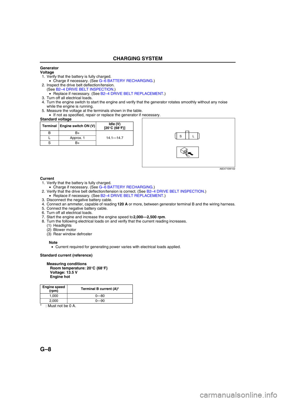
Generator
Voltage
1. Verify that the battery is fully charged.
•Charge if necessary. (See G–6 BATTERY RECHARGING.)
2. Inspect the drive belt deflection/tension.
(See B2–4 DRIVE BELT INSPECTION.)
•Replace if necessary. (See B2–4 DRIVE BELT REPLACEMENT.)
3. Turn off all electrical loads.
4. Turn the engine switch to start the engine and verify that the generator rotates smoothly without any noise
while the engine is running.
5. Measure the voltage at the terminals shown in the table.
•If not as specified, repair or replace the generator if necessary.
Standard voltage
Current
1. Verify that the battery is fully charged.
•Charge if necessary. (See G–6 BATTERY RECHARGING.)
2. Verify that the drive belt deflection/tension is correct. (See B2–4 DRIVE BELT INSPECTION.)
•Replace if necessary. (See B2–4 DRIVE BELT REPLACEMENT.)
3. Disconnect the negative battery cable.
4. Connect an ammeter, capable of reading 120 A or more, between generator terminal B and the wiring harness.
5. Connect the negative battery cable.
6. Turn off all electrical loads.
7. Start the engine and increase the engine speed to 2,000—2,500 rpm.
8. Turn the following electrical loads on and verify that the current reading increases.
(1) Headlights
(2) Blower motor
(3) Rear window defroster
Note
•Current required for generating power varies with electrical loads applied.
Standard current (reference)
Measuring conditions
Room temperature: 20°C {68°F}
Voltage: 13.5 V
Engine hot
* : Must not be 0 A.
End Of Sie
Terminal Engine switch ON (V)Idle (V)
[20°C {68°F}]
BB+
14.1—14.7 LApprox. 1
SB+
SL
A6E4710W102
Engine speed
(rpm)Terminal B current (A)*
1,000 0—80
2,000 0—90
Page 392 of 909

STARTING SYSTEM
G–9
G
STARTER REMOVAL/INSTALLATIONA6E471418400202
Warning
•When the battery cables are connected, touching the vehicle body with starter terminal B will
generate sparks. This can cause personal injury, fire, and damage to the electrical components.
Always disconnect the battery negative cables before performing the following operation.
1. Disconnect the negative battery cable.
2. Remove the plug hole plate. (L8, LF, and L3 engine models)
3. Remove the engine cover. (MZR-CD (RF Turbo) engine model) (See B2–9 TIMING BELT REMOVAL/
INSTALLATION.)
4. Remove the air cleaner assembly. (L8, LF, and L3 engine models).
5. Remove the under cover.
6. Remove the oil filter and oil cooler component with the cooling hose connected. Position the oil filter and oil
cooler component so that it is out of the way. (L3 engine model (4WD))
7. Remove the solenoid valve assembly with the vacuum hose and the connector connected. Position the
solenoid valve assembly so that it is out of the way. (MZR-CD (RF Turbo) engine model)
8. Remove the release cylinder with the oil pipe connected. Position the release cylinder so that it is out of the
way. (MTX)
9. Remove in the order indicated in the table.
10. Install in the reverse order of removal.
STARTING SYSTEM
Page 782 of 909

S–1
S
SBODY
OUTLINE................................................................ S-2
OUTLINE OF CONSTRUCTION ......................... S-2
FEATURES .......................................................... S-2
EXTERIOR ATTACHMENT.................................... S-2
OUTLINE ............................................................. S-2
STRUCTURAL VIEW........................................... S-2
TRIM....................................................................... S-3
OUTLINE ............................................................. S-3
STRUCTURAL VIEW........................................... S-3
SEAT....................................................................... S-4
OUTLINE ............................................................. S-4
STRUCTURAL VIEW........................................... S-4
OUTLINE................................................................ S-5
SUPPLEMENTAL SERVICE INFORMATION ..... S-5
LOCATION INDEX................................................. S-6
EXTERIOR........................................................... S-6
INTERIOR ............................................................ S-7
LIFTGATE............................................................... S-8
LIFTGATE REMOVAL/INSTALLATION............... S-8
LIFTGATE DISASSEMBLY/ASSEMBLY ............. S-9
LIFTGATE ADJUSTMENT................................. S-10
EXTERIOR ATTACHMENT.................................. S-11
EXTRACTOR CHAMBER
REMOVAL/INSTALLATION ............................ S-11
REAR SPOILER REMOVAL/INSTALLATION ... S-11
ROOF RAIL REMOVAL/INSTALLATION .......... S-11
MOLDING............................................................. S-12
ROOF MOLDING REMOVAL ............................ S-12
ROOF MOLDING INSTALLATION .................... S-12
WINDOW GLASS................................................. S-14
SIDE WINDOW GLASS REMOVAL .................. S-14
SIDE WINDOW GLASS INSTALLATION .......... S-14
REAR WINDOW GLASS REMOVAL................. S-16
REAR WINDOW GLASS INSTALLATION ......... S-17
SLIDING SUNROOF............................................. S-20
REAR DRAIN HOSE REMOVAL ....................... S-20
TRIM..................................................................... S-21
C-PILLAR TRIM REMOVAL/INSTALLATION .... S-21
D-PILLAR TRIM REMOVAL/INSTALLATION .... S-21
TRUNK SIDE TRIM
REMOVAL/INSTALLATION ............................ S-21
TRUNK SIDE UPPER TRIM
REMOVAL/INSTALLATION ............................ S-22
TRUNK END TRIM
REMOVAL/INSTALLATION ............................ S-23
LIFTGATE UPPER TRIM
REMOVAL/INSTALLATION ............................ S-23
LIFTGATE SIDE TRIM
REMOVAL/INSTALLATION ............................ S-24
LIFTGATE LOWER TRIM
REMOVAL/INSTALLATION ............................ S-24TONNEAU COVER ANCHOR
REMOVAL/INSTALLATION ............................ S-25
HEADLINER......................................................... S-26
HEADLINER REMOVAL/INSTALLATION ......... S-26
FLOOR COVERING............................................. S-27
FRONT FLOOR COVERING
REMOVAL/INSTALLATION ............................ S-27
SEAT BELT.......................................................... S-28
REAR SIDE SEAT BELT
REMOVAL/INSTALLATION ............................ S-28
REAR CENTER SEAT BELT
REMOVAL/INSTALLATION ............................ S-28
SEAT..................................................................... S-29
REAR SEAT REMOVAL/INSTALLATION.......... S-29
REAR SEAT DISASSEMBLY/ASSEMBLY ........ S-29 FEATURES
SERVICE
Page 786 of 909

OUTLINE
S–5
S
SUPPLEMENTAL SERVICE INFORMATIONA6E770201086203•The following changes and/or additions have been made since publication of the Mazda6 Workshop Manual
(1730-1*-02C).
Liftgate
•Removal/Installation procedure has been modified.
•Disassembly/Assembly procedure has been modified.
•Adjustment procedure has been modified.
Extractor chamber
•Removal/Installation procedure has been modified.
Roof rail
•Removal/Installation procedure has been added.
Rear spoiler
•Removal/Installation procedure has been modified.
Roof molding
•Removal procedure has been modified.
•Installation procedure has been modified.
Side window glass
•Removal procedure has been added.
•Installation procedure has been added.
Rear window glass
•Removal procedure has been modified.
•Installation procedure has been modified.
Rear drain hose
•Removal procedure has been modified.
C-pillar trim
•Removal/Installation procedure has been modified.
D-pillar trim
•Removal/Installation procedure has been added.
Trunk side trim
•Removal/Installation procedure has been modified.
Trunk side upper trim
•Removal/Installation procedure has been modified.
Trunk end trim
•Removal/Installation procedure has been modified.
Liftgate upper trim
•Removal/Installation procedure has been modified.
Liftgate side trim
•Removal/Installation procedure has been modified.
Liftgate lower trim
•Removal/Installation procedure has been modified.
Tonneau cover anchor
•Removal/Installation procedure has been added.
Headliner
•Removal/Installation procedure has been modified.
Front floor covering
•Removal/Installation procedure has been modified.
Rear side seat belt
•Removal/Installation procedure has been modified.
Rear center seat belt
•Removal/Installation procedure has been modified.
Rear seat
•Removal/Installation procedure has been modified.
•Disassembly/Assembly procedure has been modified.
End Of Sie
OUTLINE
Page 788 of 909

LOCATION INDEX
S–7
S
INTERIORA6E770001086202
.
End Of Sie
1
10
12
13
11 14
2
3
4
5
6
7
89
A6E77001104
1 Liftgate side trim
(See S–24 LIFTGATE SIDE TRIM REMOVAL/
INSTALLATION)
2 C-pillar trim
(See S–21 C-PILLAR TRIM REMOVAL/
INSTALLATION)
3 D-pillar trim
(See S–21 D-PILLAR TRIM REMOVAL/
INSTALLATION)
4 Trunk side upper trim
(See S–22 TRUNK SIDE UPPER TRIM REMOVAL/
INSTALLATION)
5 Trunk side trim
(See S–21 TRUNK SIDE TRIM REMOVAL/
INSTALLATION)
6 Extractor chamber
(See S–11 EXTRACTOR CHAMBER REMOVAL/
INSTALLATION)
7 Trunk end trim
(See S–23 TRUNK END TRIM REMOVAL/
INSTALLATION)8 Rear seat
(See S–29 REAR SEAT REMOVAL/
INSTALLATION)
(See S–30 REAR SEAT DISASSEMBLY/
ASSEMBLY)
9 Floor covering
(See S–27 FRONT FLOOR COVERING
REMOVAL/INSTALLATION)
10 Tonneau cover anchor
(See S–25 TONNEAU COVER ANCHOR
REMOVAL/INSTALLATION)
11 Headliner
(See S–26 HEADLINER REMOVAL/
INSTALLATION)
12 Rear center seat belt
(See S–28 REAR CENTER SEAT BELT
REMOVAL/INSTALLATION)
13 Liftgate upper trim
(See S–23 LIFTGATE UPPER TRIM REMOVAL/
INSTALLATION)
14 Liftgate lower trim
(See S–24 LIFTGATE LOWER TRIM REMOVAL/
INSTALLATION)
Page 807 of 909

S–26
HEADLINER
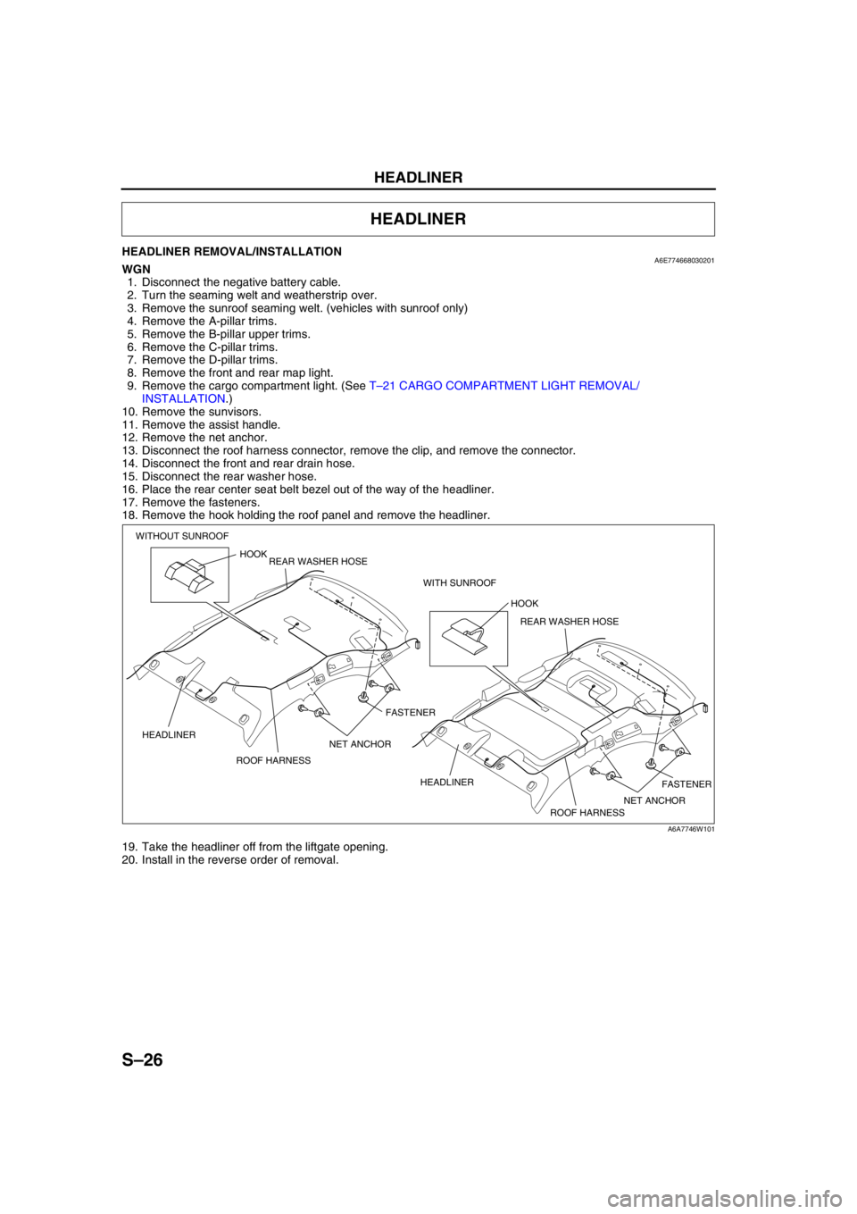
HEADLINER REMOVAL/INSTALLATIONA6E774668030201WGN
1. Disconnect the negative battery cable.
2. Turn the seaming welt and weatherstrip over.
3. Remove the sunroof seaming welt. (vehicles with sunroof only)
4. Remove the A-pillar trims.
5. Remove the B-pillar upper trims.
6. Remove the C-pillar trims.
7. Remove the D-pillar trims.
8. Remove the front and rear map light.
9. Remove the cargo compartment light. (See T–21 CARGO COMPARTMENT LIGHT REMOVAL/
INSTALLATION.)
10. Remove the sunvisors.
11. Remove the assist handle.
12. Remove the net anchor.
13. Disconnect the roof harness connector, remove the clip, and remove the connector.
14. Disconnect the front and rear drain hose.
15. Disconnect the rear washer hose.
16. Place the rear center seat belt bezel out of the way of the headliner.
17. Remove the fasteners.
18. Remove the hook holding the roof panel and remove the headliner.
19. Take the headliner off from the liftgate opening.
20. Install in the reverse order of removal.
End Of Sie
HEADLINER
HOOK
FASTENER
FASTENER ROOF HARNESS HEADLINERHOOK
ROOF HARNESS HEADLINER WITHOUT SUNROOF
WITH SUNROOF REAR WASHER HOSE
REAR WASHER HOSE
NET ANCHOR NET ANCHOR
A6A7746W101
Page 808 of 909

FLOOR COVERING
S–27
S
FRONT FLOOR COVERING REMOVAL/INSTALLATIONA6E774868670201WGN
1. Disconnect the negative battery cable.
2. Remove the front seats.
3. Remove the rear seat. (SeeS–29 REAR SEAT REMOVAL/INSTALLATION)
4. Remove the front scuff plates.
5. Remove the rear scuff plates.
6. Remove the console.
7. Remove the front side trims.
8. Remove the B-pillar lower trims.
9. Remove the lower anchor of the front seat belt installation bolts.
10. Remove the tire house trim.
11. Remove the fuel-filler lid opener bezel.
12. Remove the fasteners.
13. Remove the cap nuts.
14. Remove the clips.
15. Take the front floor covering off from the
passenger-side door opening.
16. Install in the reverse order of removal.
End Of Sie
FLOOR COVERING
FLOOR MATCLIPCAP NUT FASTENER
A6E77481101
Page 809 of 909

S–28
SEAT BELT
REAR SIDE SEAT BELT REMOVAL/INSTALLATIONA6E775057730201
Caution
•The rear side seat belt for 4WD models is equipped with a silencer to reduce abnormal noise while
driving. If the silencer is not installed in the proper position, the push knob may not function
properly. When attaching the silencer, be sure to attach it in the correct area as shown below.
Note
•Rear side seat belts are built into the rear seat back. See rear seat disassembly/assembly, to remove/
install the rear side seat belt.
1. Peel off the backing of the double-sided adhesive tape.
2. Attach double-sided adhesive tape to the silencer as shown.
End Of Sie
REAR CENTER SEAT BELT REMOVAL/INSTALLATIONA6E775057730202WGN
Caution
•The ELR has a spring that will unwind if the retractor's cover is removed. The spring cannot be
rewound by hand. If this occurs, the ELR will not work properly. Therefore, do not disassemble the
retractor.
1. Remove the headliner.
2. Remove the bolts.
3. Remove the rear center seat belt.
4. Install in the reverse order of removal.
End Of Sie
SEAT BELT
SILENCERRETRACTOR
mm {in} 29—35
{1.2—1.3}
-3—3
{-0.1—0.1} 60
{2.3} 60
{2.3}
60
{2.3}
60
{2.3}40
{1.5}
29—35
{1.2—1.3}
-3—3
{-0.1—0.1}
SILENCER RETRACTOR
60{2.3}
A6E77502101
39—78 N·m
{3.9—8.0 kgf·m, 29—57 ft·lbf}
REAR CENTER
SEAT BELT
BOLT
A6A7750W101