brake light MAZDA 6 2002 Suplement Service Manual
[x] Cancel search | Manufacturer: MAZDA, Model Year: 2002, Model line: 6, Model: MAZDA 6 2002Pages: 909, PDF Size: 17.16 MB
Page 744 of 909

CONVENTIONAL BRAKE SYSTEM
P–11
P
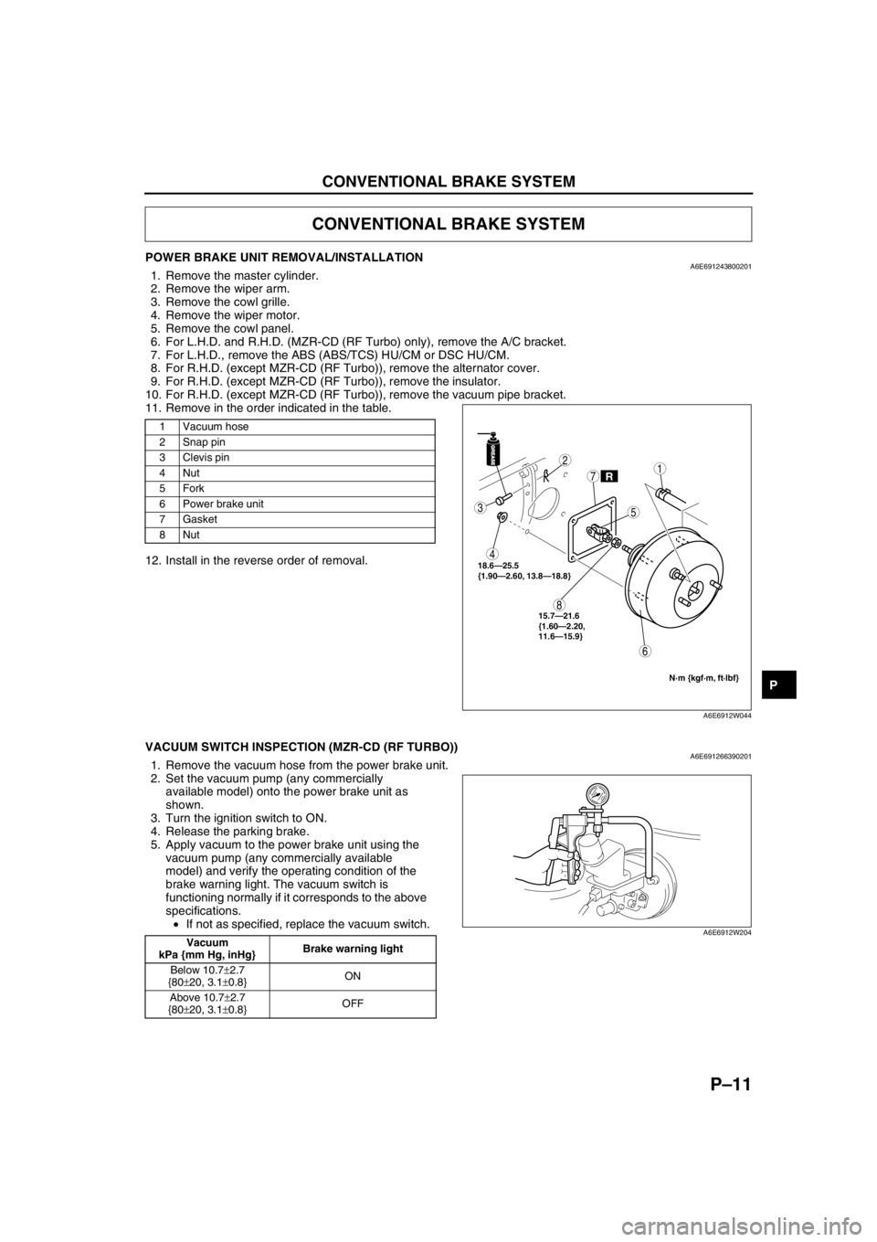
POWER BRAKE UNIT REMOVAL/INSTALLATIONA6E6912438002011. Remove the master cylinder.
2. Remove the wiper arm.
3. Remove the cowl grille.
4. Remove the wiper motor.
5. Remove the cowl panel.
6. For L.H.D. and R.H.D. (MZR-CD (RF Turbo) only), remove the A/C bracket.
7. For L.H.D., remove the ABS (ABS/TCS) HU/CM or DSC HU/CM.
8. For R.H.D. (except MZR-CD (RF Turbo)), remove the alternator cover.
9. For R.H.D. (except MZR-CD (RF Turbo)), remove the insulator.
10. For R.H.D. (except MZR-CD (RF Turbo)), remove the vacuum pipe bracket.
11. Remove in the order indicated in the table.
12. Install in the reverse order of removal.
End Of Sie
VACUUM SWITCH INSPECTION (MZR-CD (RF TURBO))A6E6912663902011. Remove the vacuum hose from the power brake unit.
2. Set the vacuum pump (any commercially
available model) onto the power brake unit as
shown.
3. Turn the ignition switch to ON.
4. Release the parking brake.
5. Apply vacuum to the power brake unit using the
vacuum pump (any commercially available
model) and verify the operating condition of the
brake warning light. The vacuum switch is
functioning normally if it corresponds to the above
specifications.
•If not as specified, replace the vacuum switch.
End Of Sie
CONVENTIONAL BRAKE SYSTEM
1 Vacuum hose
2 Snap pin
3Clevis pin
4Nut
5Fork
6 Power brake unit
7Gasket
8Nut
GREASEGREASE
R
3
4
8
6
2
7
5
1
18.6—25.5
{1.90—2.60, 13.8—18.8}
N·m {kgf·m, ft·lbf}
15.7—21.6
{1.60—2.20,
11.6—15.9}
A6E6912W044
Vacuum
kPa {mm Hg, inHg}Brake warning light
Below 10.7±2.7
{80±20, 3.1±0.8}ON
Above 10.7±2.7
{80±20, 3.1±0.8}OFFA6E6912W204
Page 750 of 909

PARKING BRAKE SYSTEM, DYNAMIC STABILITY CONTROL
P–17
P
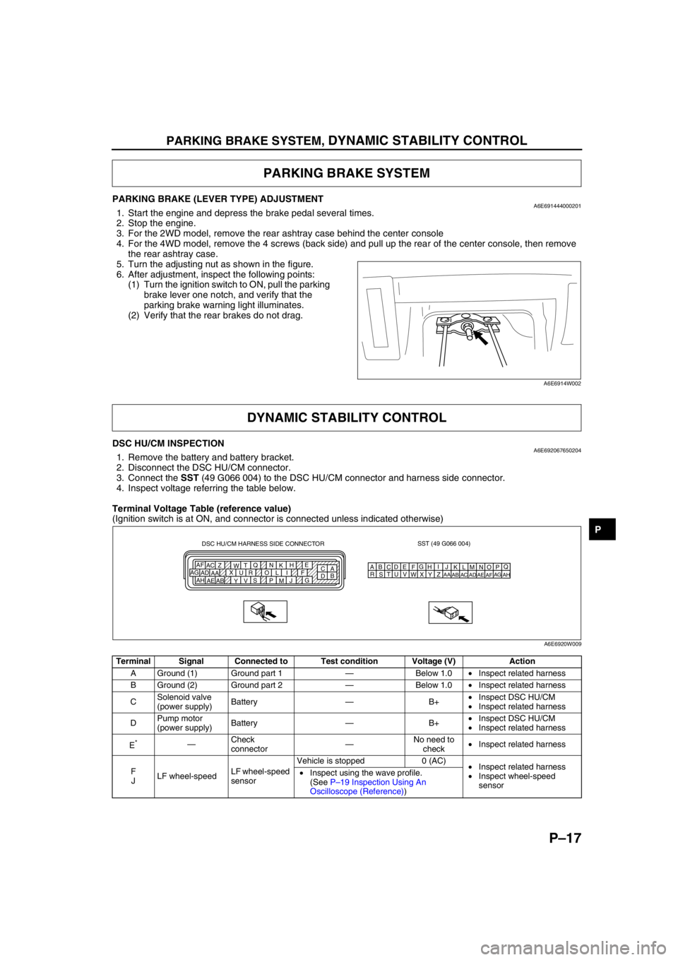
PARKING BRAKE (LEVER TYPE) ADJUSTMENTA6E6914440002011. Start the engine and depress the brake pedal several times.
2. Stop the engine.
3. For the 2WD model, remove the rear ashtray case behind the center console
4. For the 4WD model, remove the 4 screws (back side) and pull up the rear of the center console, then remove
the rear ashtray case.
5. Turn the adjusting nut as shown in the figure.
6. After adjustment, inspect the following points:
(1) Turn the ignition switch to ON, pull the parking
brake lever one notch, and verify that the
parking brake warning light illuminates.
(2) Verify that the rear brakes do not drag.
End Of Sie
DSC HU/CM INSPECTIONA6E6920676502041. Remove the battery and battery bracket.
2. Disconnect the DSC HU/CM connector.
3. Connect the SST (49 G066 004) to the DSC HU/CM connector and harness side connector.
4. Inspect voltage referring the table below.
Terminal Voltage Table (reference value)
(Ignition switch is at ON, and connector is connected unless indicated otherwise)
PARKING BRAKE SYSTEM
A6E6914W002
DYNAMIC STABILITY CONTROL
Terminal Signal Connected to Test condition Voltage (V) Action
A Ground (1) Ground part 1—Below 1.0•Inspect related harness
B Ground (2) Ground part 2—Below 1.0•Inspect related harness
CSolenoid valve
(power supply)Battery—B+•Inspect DSC HU/CM
•Inspect related harness
DPump motor
(power supply)Battery—B+•Inspect DSC HU/CM
•Inspect related harness
E
*—Check
connector—No need to
check•Inspect related harness
F
JLF wheel-speedLF wheel-speed
sensorVehicle is stopped 0 (AC)
•Inspect related harness
•Inspect wheel-speed
sensor •Inspect using the wave profile.
(See P–19 Inspection Using An
Oscilloscope (Reference))
SST (49 G066 004)
AQ
B
CDE
FG
HI
J DSC HU/CM HARNESS SIDE CONNECTOR
A
C E
H
K N Q
T
W Z AC AF
F I L O R U X
AA AD AG
G
J
M P S
V
Y AB AE AHB
DKN
T
WZ
AC
AFLO
RU
XAA
ADAGMP
SV
YAB
AEAH
A6E6920W009
Page 756 of 909

ON-BOARD DIAGNOSTIC
P–23
P
PMPSTAT
(Pump motor output state)ON/OFF•Pump motor is activated:
ON
•Pump motor is deactivated:
OFFInspect DSC HU/CM
—
BRK_FLUID (with DSC only)
(Brake fluid level sensor input)OK/LOW•Brake fluid is above LOW:
OK
•Brake fluid is below LOW:
LOWInspect brake fluid
level.
Inspect brake fluid
level sensor.—
BOO_ABS
(Brake pedal switch input)ON/OFF•Brake pedal is depressed:
ON
•Brake pedal is released:
OFFInspect brake switch.
ABS (ABS/
TCS): Y
DSC: L
ABS_LAMP
(ABS warning light driver
output state)ON/OFF•ABS warning light is
illuminated: ON
•ABS warning light is not
illuminated: OFFInspect ABS warning
light.
—
BRAKE_LMP
(BRAKE system warning light
output state)ON/OFF•BRAKE system warning
light is illuminated: ON
•BRAKE system warning
light is not illuminated: OFFInspect BRAKE
system warning light.
—
ABSRR_O
(Right rear ABS pressure
reduction solenoid valve
output state)ON/OFF•During ABS control: ON/
OFF
(solenoid valve is activated/
deactivated)
•Not ABS control: OFF
(solenoid valve is
deactivated)Internal fault of ABS
(ABS/TCS) or DSC
HU/CM. Replace ABS
(ABS/TCS) or DSC
HU/CM.—
ABSLR_O
(Left rear ABS pressure
reduction solenoid valve
output state)ON/OFF•During ABS or EBD control:
ON/OFF
(solenoid valve is activated/
deactivated)
•Not ABS and EBD control:
OFF
(solenoid valve is
deactivated)Internal fault of ABS
(ABS/TCS) or DSC
HU/CM. Replace ABS
(ABS/TCS) or DSC
HU/CM.—
ABSRF_O
(Right front ABS pressure
reduction solenoid valve
output state)ON/OFF•During ABS control: ON/
OFF
(solenoid valve is activated/
deactivated)
•Not ABS control: OFF
(solenoid valve is
deactivated)Internal fault of ABS
(ABS/TCS) or DSC
HU/CM. Replace ABS
(ABS/TCS) or DSC
HU/CM.—
ABSLF_O
(Left front ABS pressure
reduction solenoid valve
output state)ON/OFF•During ABS control: ON/
OFF
(solenoid valve is activated/
deactivated)
•Not ABS control: OFF
(solenoid valve is
deactivated)Internal fault of ABS
(ABS/TCS) or DSC
HU/CM. Replace ABS
(ABS/TCS) or DSC
HU/CM.—
ABSRR_I
(Right rear ABS pressure
reduction solenoid valve
output state)ON/OFF•During ABS control: ON/
OFF
(solenoid valve is activated/
deactivated)
•Not ABS control: OFF
(solenoid valve is
deactivated)Internal fault of ABS
(ABS/TCS) or DSC
HU/CM. Replace ABS
(ABS/TCS) or DSC
HU/CM.—
ABSLR_I
(Left rear ABS pressure
retention solenoid valve output
state)ON/OFF•During ABS or EBD control:
ON/OFF
(solenoid valve is activated/
deactivated)
•Not ABS and EBD control:
OFF
(solenoid valve is
deactivated)Internal fault of ABS
(ABS/TCS) or DSC
HU/CM. Replace ABS
(ABS/TCS) or DSC
HU/CM.— PID Name
(Definition)Unit/Condition Condition/Specification ActionABS (ABS/
TCS) HU/CM or
DSC HU/CM
terminal
Page 783 of 909

S–2
OUTLINE, EXTERIOR ATTACHMENT
OUTLINE OF CONSTRUCTIONA6E770201086201•The construction and operation of the body system is essentially carried over from that of the current Mazda6
(GG) model, except for the following features. (See Mazda6 Training Manual 3359-1*-02C)
End Of Sie
FEATURESA6E770201086202Improved Marketability
•A rear spoiler with a built in high-mount brake light has been adopted. (WGN)
•A roof rail has been adopted. (WGN)
•A tonneau cover with an attached net has been adopted. (WGN)
•A fixed rear seat cushion has been adopted. (4WD WGN)
End Of Sie
OUTLINEA6E772801092201•A rear spoiler with a built in high-mount brake light has been adopted.
•A roof rail has been adopted.
End Of Sie
STRUCTURAL VIEWA6E772801092202
.
End Of Sie
OUTLINE
EXTERIOR ATTACHMENT
1
2
A6E7728T101
1 Roof rail2 Rear spoiler
Page 792 of 909

EXTERIOR ATTACHMENT
S–11
S
EXTRACTOR CHAMBER REMOVAL/INSTALLATIONA6E772851920201WGN
1. Remove the rear bumper.
2. Remove the left side trunk side trim.
3. Squeeze the clips with your fingers and remove
the extractor chamber from the vehicle side.
4. Install in the reverse order of removal.
End Of Sie
REAR SPOILER REMOVAL/INSTALLATIONA6E772851920202WGN
1. Disconnect the negative battery cable.
2. Remove the liftgate upper trim. (SeeS–23 LIFTGATE UPPER TRIM REMOVAL/INSTALLATION)
3. Remove the bolts and nuts.
4. Disconnect the high-mount brake light connector.
5. Disengage the pin A from the body, then remove
the rear spoiler.
6. Install in the reverse order of removal.
End Of Sie
ROOF RAIL REMOVAL/INSTALLATIONA6E7728517202011. Remove the headliner.
2. Remove the nuts.
3. Remove the roof rail.
4. Install in the reverse order of removal.
End Of Sie
EXTERIOR ATTACHMENT
EXTRACTOR
CHAMBER CLIP AA
A
A6E77281103
BOLT REAR SPOILER
HIGH-MOUNT BRAKE
LIGHT CONNECTOR
NUTPIN A
AA
N·m {kgf·cm, in·lbf} 7.8—9.8
{79—100, 68.8—86.7} 8.9—12.7 {90—130, 79—112}
A6A7728W104
ROOF RAIL
6.9—9.8 N·m
{70—100 kgf·cm,
60.8—86.7 in·lbf}NUT
A6A7728W105
Page 804 of 909

TRIM
S–23
S
TRUNK END TRIM REMOVAL/INSTALLATIONA6E774468890201WGN
1. Pull the trunk end trim upward, then disengage
clips A and pins B from the body.
2. Remove the trunk end trim.
3. Install in the reverse order of removal.
End Of Sie
LIFTGATE UPPER TRIM REMOVAL/INSTALLATIONA6E774468930201WGN
Without rear spoiler
Caution
•Removing the liftgate upper trim by pulling on the middle section of the trim could damage the
high-mount brake light. When removing the trim, be sure to pull on the side edges of the trim only.
1. Pull the liftgate upper trim on the side edges
towards you, then disengage pins A from the
body.
2. Pull the middle section of the trim towards you
and disengage clips B and pin C from the body.
3. Remove the liftgate upper trim.
4. Install in the reverse order of removal.
With rear spoiler
1. Pull the liftgate upper trim toward you, then
disengage the pin A, C and clip B from the body.
2. Remove the liftgate upper trim.
3. Install in the reverse order of removal.
End Of Sie
AB
A
A
B
A
A
A B
TRUNK END TRIM
PIN B
CLIP A
A6A7744W108
AC B
AB
CLIP B
PIN A LIFTGATE UPPER TRIM
PIN C
A6A7744W109
ABAB
C
CLIP BPIN C LIFTGATE UPPER TRIM
PIN A
A6A7744W110
Page 812 of 909

T–1
T
TBODY ELECTRICAL SYSTEM
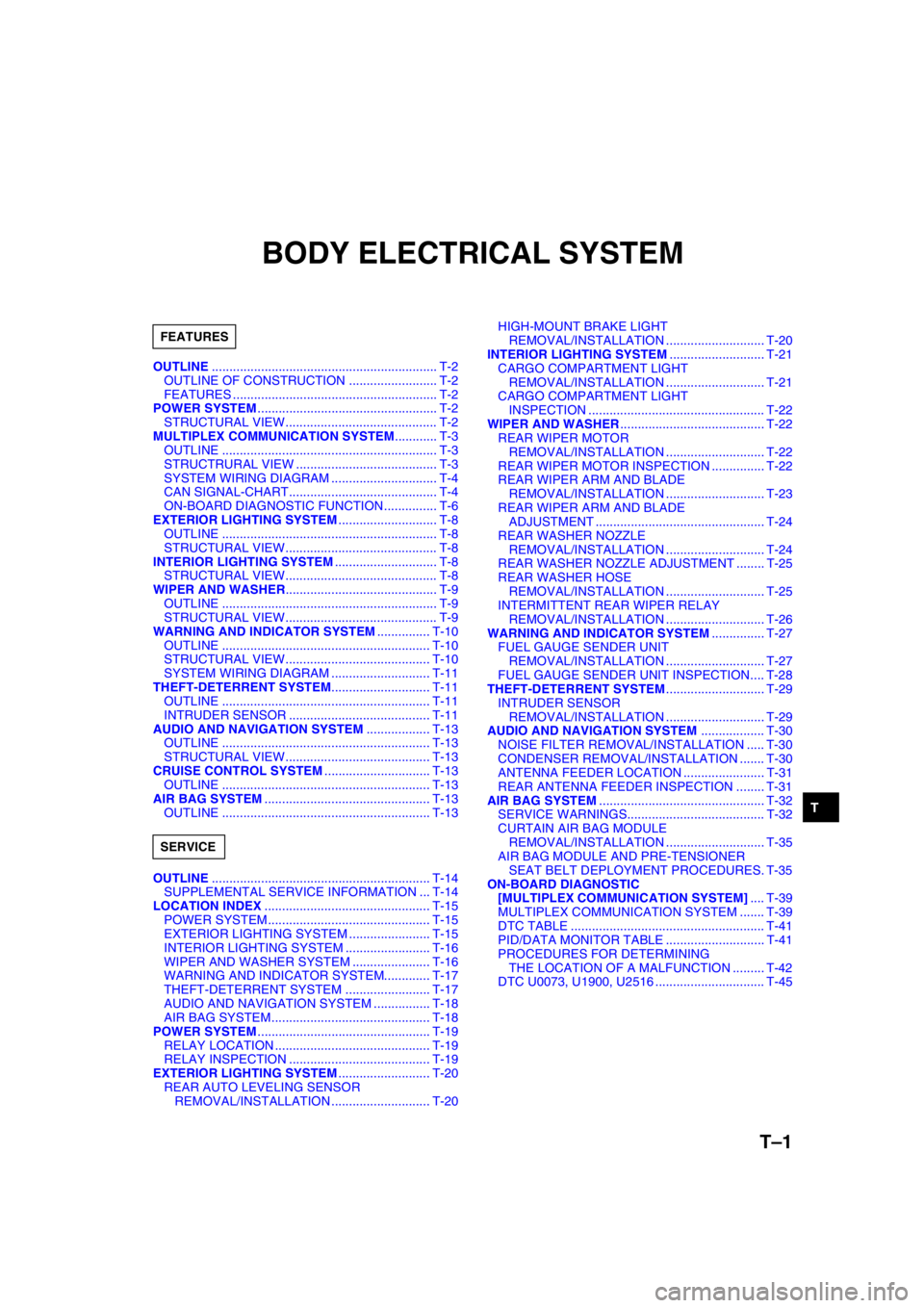
OUTLINE................................................................ T-2
OUTLINE OF CONSTRUCTION ......................... T-2
FEATURES .......................................................... T-2
POWER SYSTEM................................................... T-2
STRUCTURAL VIEW........................................... T-2
MULTIPLEX COMMUNICATION SYSTEM............ T-3
OUTLINE ............................................................. T-3
STRUCTRURAL VIEW ........................................ T-3
SYSTEM WIRING DIAGRAM .............................. T-4
CAN SIGNAL-CHART.......................................... T-4
ON-BOARD DIAGNOSTIC FUNCTION............... T-6
EXTERIOR LIGHTING SYSTEM............................ T-8
OUTLINE ............................................................. T-8
STRUCTURAL VIEW........................................... T-8
INTERIOR LIGHTING SYSTEM............................. T-8
STRUCTURAL VIEW........................................... T-8
WIPER AND WASHER........................................... T-9
OUTLINE ............................................................. T-9
STRUCTURAL VIEW........................................... T-9
WARNING AND INDICATOR SYSTEM............... T-10
OUTLINE ........................................................... T-10
STRUCTURAL VIEW......................................... T-10
SYSTEM WIRING DIAGRAM ............................ T-11
THEFT-DETERRENT SYSTEM............................ T-11
OUTLINE ........................................................... T-11
INTRUDER SENSOR ........................................ T-11
AUDIO AND NAVIGATION SYSTEM.................. T-13
OUTLINE ........................................................... T-13
STRUCTURAL VIEW......................................... T-13
CRUISE CONTROL SYSTEM.............................. T-13
OUTLINE ........................................................... T-13
AIR BAG SYSTEM............................................... T-13
OUTLINE ........................................................... T-13
OUTLINE.............................................................. T-14
SUPPLEMENTAL SERVICE INFORMATION ... T-14
LOCATION INDEX............................................... T-15
POWER SYSTEM.............................................. T-15
EXTERIOR LIGHTING SYSTEM ....................... T-15
INTERIOR LIGHTING SYSTEM ........................ T-16
WIPER AND WASHER SYSTEM ...................... T-16
WARNING AND INDICATOR SYSTEM............. T-17
THEFT-DETERRENT SYSTEM ........................ T-17
AUDIO AND NAVIGATION SYSTEM ................ T-18
AIR BAG SYSTEM............................................. T-18
POWER SYSTEM................................................. T-19
RELAY LOCATION ............................................ T-19
RELAY INSPECTION ........................................ T-19
EXTERIOR LIGHTING SYSTEM.......................... T-20
REAR AUTO LEVELING SENSOR
REMOVAL/INSTALLATION ............................ T-20HIGH-MOUNT BRAKE LIGHT
REMOVAL/INSTALLATION ............................ T-20
INTERIOR LIGHTING SYSTEM........................... T-21
CARGO COMPARTMENT LIGHT
REMOVAL/INSTALLATION ............................ T-21
CARGO COMPARTMENT LIGHT
INSPECTION .................................................. T-22
WIPER AND WASHER......................................... T-22
REAR WIPER MOTOR
REMOVAL/INSTALLATION ............................ T-22
REAR WIPER MOTOR INSPECTION ............... T-22
REAR WIPER ARM AND BLADE
REMOVAL/INSTALLATION ............................ T-23
REAR WIPER ARM AND BLADE
ADJUSTMENT ................................................ T-24
REAR WASHER NOZZLE
REMOVAL/INSTALLATION ............................ T-24
REAR WASHER NOZZLE ADJUSTMENT ........ T-25
REAR WASHER HOSE
REMOVAL/INSTALLATION ............................ T-25
INTERMITTENT REAR WIPER RELAY
REMOVAL/INSTALLATION ............................ T-26
WARNING AND INDICATOR SYSTEM............... T-27
FUEL GAUGE SENDER UNIT
REMOVAL/INSTALLATION ............................ T-27
FUEL GAUGE SENDER UNIT INSPECTION.... T-28
THEFT-DETERRENT SYSTEM............................ T-29
INTRUDER SENSOR
REMOVAL/INSTALLATION ............................ T-29
AUDIO AND NAVIGATION SYSTEM.................. T-30
NOISE FILTER REMOVAL/INSTALLATION ..... T-30
CONDENSER REMOVAL/INSTALLATION ....... T-30
ANTENNA FEEDER LOCATION ....................... T-31
REAR ANTENNA FEEDER INSPECTION ........ T-31
AIR BAG SYSTEM............................................... T-32
SERVICE WARNINGS....................................... T-32
CURTAIN AIR BAG MODULE
REMOVAL/INSTALLATION ............................ T-35
AIR BAG MODULE AND PRE-TENSIONER
SEAT BELT DEPLOYMENT PROCEDURES. T-35
ON-BOARD DIAGNOSTIC
[MULTIPLEX COMMUNICATION SYSTEM].... T-39
MULTIPLEX COMMUNICATION SYSTEM ....... T-39
DTC TABLE ....................................................... T-41
PID/DATA MONITOR TABLE ............................ T-41
PROCEDURES FOR DETERMINING
THE LOCATION OF A MALFUNCTION ......... T-42
DTC U0073, U1900, U2516 ............................... T-45 FEATURES
SERVICE
Page 813 of 909

T–2
OUTLINE, POWER SYSTEM
OUTLINE OF CONSTRUCTIONA6E810201088201•The construction and operation of the body electrical system is essentially carried over from that of the current
Mazda6 (GG) model, except for the following features. (See Mazda6 Training Manual 3359-1*-02C)
End Of Sie
FEATURESA6E810201088202Improved Safety
•There are two types of high-mount brake lights. (WGN)
Improved Marketability
•A cargo compartment light has been adopted. (WGN)
•The installation positions of the rear wiper and washer components have been changed. (WGN)
•A fuel gauge sender sub-unit has been adopted. (4WD)
•A 4WD indicator light, glow indicator light and sedimentor warning light have been adopted.
•The installation positions of the condenser and the noise filter have been changed. (WGN)
•An antenna feeder has been adopted. (WGN)
•A rear auto leveling sensor especially for the 4WD has been adopted. (4WD)
Improved Security
•A rear intruder sensor has been adopted. (WGN)
End Of Sie
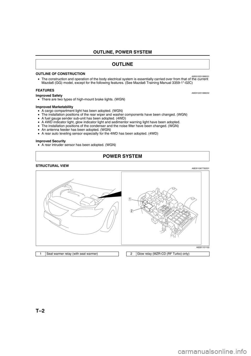
STRUCTURAL VIEWA6E811067730201
.
End Of Sie
OUTLINE
POWER SYSTEM
2
1
A6E81101102
1 Seat warmer relay (with seat warmer)2 Glow relay (MZR-CD (RF Turbo) only)
Page 815 of 909

T–4
MULTIPLEX COMMUNICATION SYSTEM
SYSTEM WIRING DIAGRAMA6E811155430203
.
End Of SieCAN SIGNAL-CHARTA6E811155430204
OUT: Output (sends signal)
IN: Input (receives signal)
1
2
67
3
8
4
5
ROAF AG
HG
2M2J2W
2X
9
10
CAN_L
CAN_H
A6E81111102
1PCM
2 DSC HU/CM (with DSC)
3 ABS (ABS/TCS) HU/CM (with ABS (ABS/TCS))
4 Data link connector-2
5 Instrument cluster
6 TCM (JA5AX-EL)7 4WD control module (4WD)
8Twist pair
9 2R (except MZR-CD (RF Turbo))
39 (MZR-CD (RF Turbo))
10 2U (except MZR-CD (RF Turbo))
13 (MZR-CD (RF Turbo))
SignalMultiplex module
PCM TCMABS (ABS/TCS)
HU/CM or
DSC HU/CM4WD control
moduleInstrument
cluster
Accelerator pedal position
(MZR-CD (RF Turbo))OUT IN IN–IN
Air induction type OUT–IN––
ATF temperature IN OUT–––
AT warning light conditions
(JA5AX-EL)IN OUT––IN
Battery reconnection
(except MZR-CD (RF
Turbo))OUT IN–––
Brake system configuration
(EBD/ABS/TCS/DSC)IN–OUT–IN
Brake system
statusABS IN–OUT––
EBD/ABS/
TCS/DSC––OUT IN IN
Brake system warning light
conditions (brake fluid level
sensor)––IN–OUT
Country OUT–IN––
Coupling torque (with
DSC)––IN OUT–
Coupling torque request
(with DSC)––OUT IN–
Page 819 of 909

T–8
EXTERIOR LIGHTING SYSTEM, INTERIOR LIGHTING SYSTEM
OUTLINEA6E811201052201•In-vehicle-type high-mount brake light and rear spoiler type high-mount brake light have been adopted. (WGN)
End Of Sie
STRUCTURAL VIEWA6E811201052202
.
End Of Sie
STRUCTURAL VIEWA6E811401052201
.
End Of Sie
EXTERIOR LIGHTING SYSTEM
2
1
A6E8112T101
1 High-mount brake light (in-vehicle-type)2 High-mount brake light (rear spoiler type)
INTERIOR LIGHTING SYSTEM
FRONT
1
A6E81141001
1 Cargo compartment light