brake light MAZDA 6 2002 Suplement Owner's Manual
[x] Cancel search | Manufacturer: MAZDA, Model Year: 2002, Model line: 6, Model: MAZDA 6 2002Pages: 909, PDF Size: 17.16 MB
Page 430 of 909

AUTOMATIC TRANSAXLE
K2–15
K2
X : Available
End Of SiePOWERTRAIN DESCRIPTIONA6E571401030207Outline
•In the powertrain system, the hydraulic pressure transported by the control valve operates the clutch, and
brake, and the planetary gear changes the gear ratio according to the driving conditions.
Structure
•The powertrain system consists of seven pairs of clutches, brake, brake band, two pairs of one-way clutches,
and simple type planetary gears.
Duty
typePressure
control
solenoidXX XX X
2-4 brake
solenoid
valveXX XX X
High
clutch
solenoid
valveXX XX X
TCC
solenoid
valveXXX
CAN
signalReduce
torque
signalXXX
Range
signalX
Turbine
speed
signalX
ATF
temperatu
re signalX
TCC
signalXX
Racing
select
signalX
MIL
indicate
request
signalX
AT
warning
light
request
signalX ComponentControl item
Shift
controlLine
pressure
controlReverse
inhibition
controlShift
transient
controlFeedbac
k controlTCC
controlN-D
select
controlSlope
mode
controlOBD
system
Page 480 of 909

AUTOMATIC TRANSAXLE
K2–65
K2
Memory Function
•The memory function stores failure information detected in the failure detection function. Once failure
information is stored, the memory will not be cleared even when the ignition switch is turned off (LOCK
position) or the malfunction is repaired.
•The stored memory (failure information) can be cleared by using the WDS or disconnecting the negative
battery cable.
Failure Indication Function
•The failure indication function illuminates the AT warning lights when the failure detection function determines
there is a malfunction.
DTC Table
X : Available
CCM:Continuous monitor
Fail-safe Function
•In the fail-safe function, minimum vehicle drivability is obtained by changing the signals that are determined as
malfunctions by the failure detection function to the preset values, and limiting the TCM control.
DTC No. On-board diagnostic function MILAT warning
light
indicationDCMonitor
itemMemory
function
P0705 TR switch circuit malfunction (Power short circuit) X X 2 CCM X
P0706 TR switch circuit malfunction (Open/ground short circuit) X X 2 CCM X
P0711 TFT sensor malfunction (Stuck) X–2 CCM X
P0712 TFT sensor circuit malfunction (Short circuit) X X 2 CCM X
P0713 TFT sensor circuit malfunction (Open circuit) X X 2 CCM X
P0715 Input/turbine speed sensor circuit malfunction X X 2 CCM X
P0720 Vehicle speedometer sensor circuit malfunction X X 2 CCM X
P0740 TCC system X–2 CCM X
P0743 TCC solenoid valve malfunction (Open/short) X X 1 CCM X
P0748 Pressure control solenoid malfunction (Open/short)–X–CCM X
P0751 Shift solenoid A malfunction (Stuck off) X–2 CCM X
P0752 Shift solenoid A malfunction (Stuck on) X–2 CCM X
P0753 Shift solenoid A malfunction (Open/short) X X 1 CCM X
P0756 Shift solenoid B malfunction (Stuck off) X–2 CCM X
P0757 Shift solenoid B malfunction (Stuck on) X–2 CCM X
P0758 Shift solenoid B malfunction (Open/short) X X 1 CCM X
P0761 Shift solenoid C malfunction (Stuck off) X–2 CCM X
P0762 Shift solenoid C malfunction (Stuck on) X–2 CCM X
P0763 Shift solenoid C malfunction (Open/short) X X 1 CCM X
P0768 Reduction timing solenoid malfunction (Open/short)–X–CCM X
P0773 Neutral shift solenoid malfunction (Open/short)–X–CCM X
P0778 2-4 brake solenoid malfunction (Open/short)–X–CCM X
P0791 Intermediate sensor malfunction (Open/short) X X 2 CCM X
P0798 High clutch solenoid malfunction (Open/short)–X–CCM X
P1710 GND return malfunction–––Other X
U0073 CAN BUS OFF X X 1 CCM X
U0100 TCM cannot receive any signals from PCM X X 1 CCM X
DTC
No.On-board diagnostic function Detection condition Fail-safe TCC
P0705Transaxle range (TR) switch
circuit malfunction (power short
circuit)•Two or more range signals
are inputted from TR switch
for 5 seconds or more•TR switch priority
D > N > P > R
•Inhibits feedback control,
SLOPE mode, torque
reduction controlAvailable
P0706Transaxle range (TR) switch
circuit malfunction (open/ground
short circuit)•No range signal is inputted
from TR switch for 100
seconds or more•Inhibits feedback control,
SLOPE mode, torque
reduction controlAvailable
Page 483 of 909

K2–68
AUTOMATIC TRANSAXLE
Parameter Identification (PID) Access
Monitor item table
End Of Sie
Display on the
testerDefinitionUnit/
ConditionTCM
terminal
2-4 B Duty 2-4 brake solenoid valve control signal in TCM ON/OFF 2V
BOO Brake switch ON/OFF 1U
DWN_SW Down switch ON/OFF 1S
GEAR Calculated gear range in TCM1ST/2ND/
3RD/4TH/5TH–
H/C Duty High clutch solenoid valve control signal in TCM % 2U
LPS Pressure control solenoid control signal in TCM % 2Y
MNL_SW M range switch ON/OFF 1AA
NSFT TIM Neutral shift solenoid valve control signal in TCM ON/OFF 2D
OSS Intermediate sensor rpm 1K, 1X
PNP TR switch (P/N position switch) ON/OFF–
RDCN TIM Reduction timing solenoid valve control signal in TCM ON/OFF 2G
RPM Engine speed rpm–
SSA/SS1 Shift solenoid A control signal in TCM ON/OFF–
SSB/SS2 Shift solenoid B control signal in TCM ON/OFF–
SSC/SS3 Shift solenoid C control signal in TCM ON/OFF–
TCCC TCC solenoid valve control signal in TCM % 2S
TCIL AT warning light control signal in TCM ON/OFF 1E
TFT ATF temperature°C1B, 1F
TFTV ATF temperature signal voltage V 1B, 1F
THOP Throttle position %–
TRD Tr switch (D range switch) ON/OFF 1Z
TRR TR switch (R position switch) ON/OFF 1W
TSS Input/turbine speed sensor rpm 1N, 2F
UP_SW Up switch ON/OFF 2C
VPWR Battery voltage V 1P
VSS Vehicle speed km/h 1V, 1M
Page 493 of 909

K2–78
AUTOMATIC TRANSAXLE
Evaluation
End Of SieAUTOMATIC TRANSAXLE FLUID (ATF) INSPECTIONA6E571419001201Automatic Transaxle Fluid (ATF) Condition Inspection
1. One way of determining whether the transaxle should be replaced is by noting:
•If the ATF is muddy or varnished.
•If the ATF smells strange or unusual.
ATF Condition
Condition Possible Cause
No 1-2 up- or downshiftStuck shift solenoid C
Stuck shift valve C
Wore 2-4 brake
Trouble intermediate sensor
No 2-3 up- or downshiftStuck shift solenoid A
Stuck shift valve A
Wore high clutch
No 3-4 up- or downshiftStuck shift solenoid B
Stuck shift valve B
Wore 2-4 brake
No 4-5 up- or downshiftStuck shift solenoid A
Stuck shift valve A
Wore direct clutch
Trouble TFT
TCC non operation shiftStuck TCC solenoid valve
Stuck TCC valve
Incorrect shift pointTrouble VSS output signal
Trouble TR switch
Trouble TP signal and engine torque signal
Excessive shift shock slippageStuck pressure control solenoid
Stuck pressure regulator valve
Stuck pressure modifier valve
Stuck accumulator valve A, B, or C
Stuck 2-4 brake solenoid valve
Stuck high clutch solenoid valve
Stuck low clutch accumulator
Stuck 2-4 brake accumlator
Stuck high clutch accumlator
Stuck direct clutch accumlator
Stuck reduction accumlator
Trouble VSS
No Engine braking effect Wore reduction brake band
Stuck reduction reducing valve
Stuck reduction timing valve
Stuck reduction timing solenoid valve
Condition Possible cause
Clear dark red Normal—
Light red (pink) Contaminated with water•Broken oil cooler inside of radiator
•Poor filler tube installation:
Problem could be occurring to parts inside the
transaxle by water contamination. If necessary,
exchange transaxle.
Reddish
brownHas burnt smell and metal
specs are foundDeteriorated ATFDefect powertrain components inside of transaxle:
Specks cause wide range of problems by plugging up
in oil pipe, control valve body and oil cooler in radiator.
•When large amount of metal specks are found.
Exchange transaxle if necessary.
•Implement flushing operation as there is a
possibility to have specks plugging up oil pipe and/
or oil cooler inside of radiator.
Has no burnt smell Normal•Discoloration by oxidation
Page 532 of 909

AUTOMATIC TRANSAXLE SHIFT MECHANISM
K2–117
K2
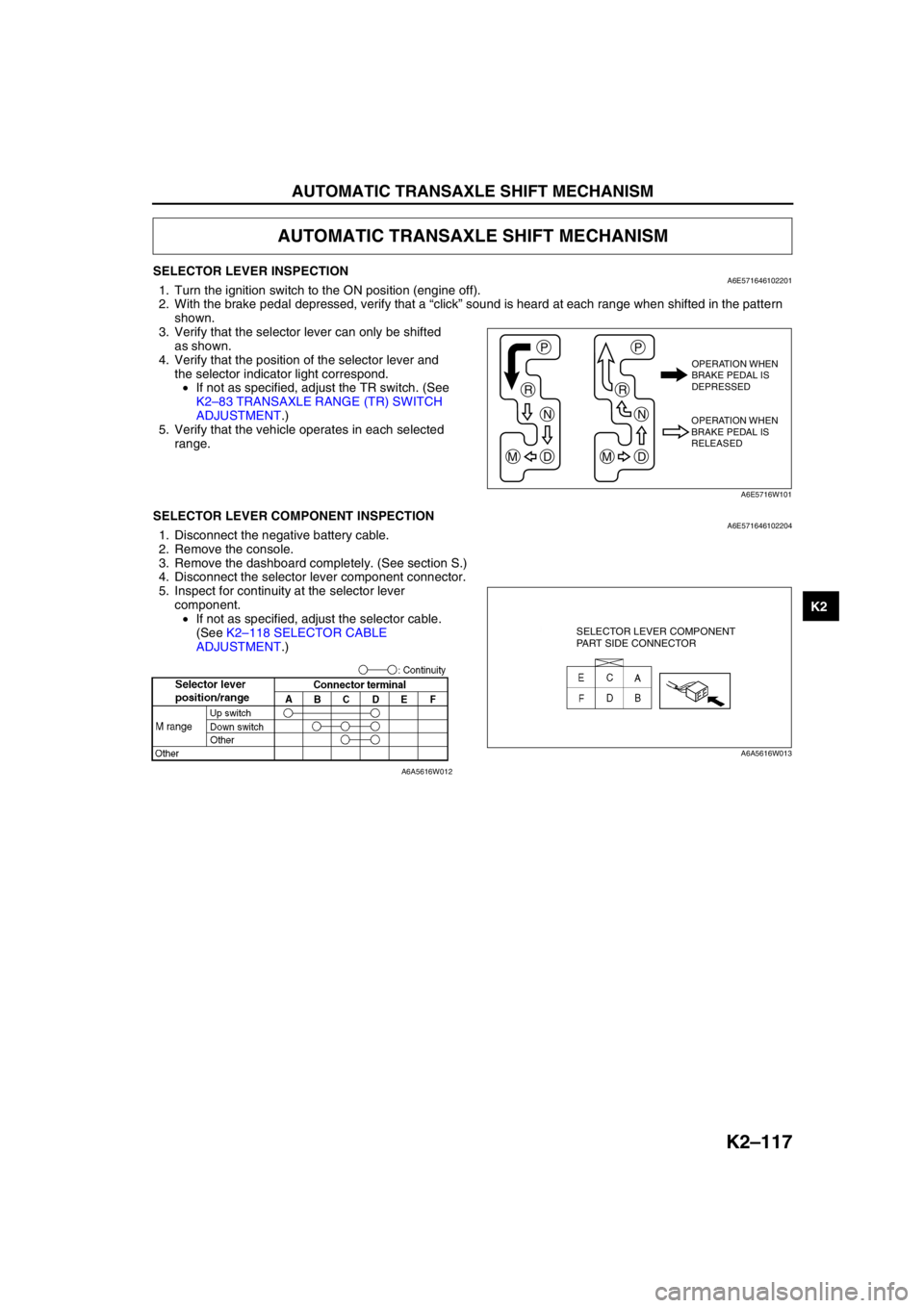
SELECTOR LEVER INSPECTIONA6E5716461022011. Turn the ignition switch to the ON position (engine off).
2. With the brake pedal depressed, verify that a “click” sound is heard at each range when shifted in the pattern
shown.
3. Verify that the selector lever can only be shifted
as shown.
4. Verify that the position of the selector lever and
the selector indicator light correspond.
•If not as specified, adjust the TR switch. (See
K2–83 TRANSAXLE RANGE (TR) SWITCH
ADJUSTMENT.)
5. Verify that the vehicle operates in each selected
range.
End Of SieSELECTOR LEVER COMPONENT INSPECTIONA6E5716461022041. Disconnect the negative battery cable.
2. Remove the console.
3. Remove the dashboard completely. (See section S.)
4. Disconnect the selector lever component connector.
5. Inspect for continuity at the selector lever
component.
•If not as specified, adjust the selector cable.
(See K2–118 SELECTOR CABLE
ADJUSTMENT.)
End Of Sie
AUTOMATIC TRANSAXLE SHIFT MECHANISM
P
R
N
DM
P
R
N
DM
OPERATION WHEN
BRAKE PEDAL IS
DEPRESSED
OPERATION WHEN
BRAKE PEDAL IS
RELEASED
A6E5716W101
SELECTOR LEVER COMPONENT
PART SIDE CONNECTOR
A6A5616W013
A6A5616W012
Page 541 of 909

K2–126
ON-BOARD DIAGNOSTIC
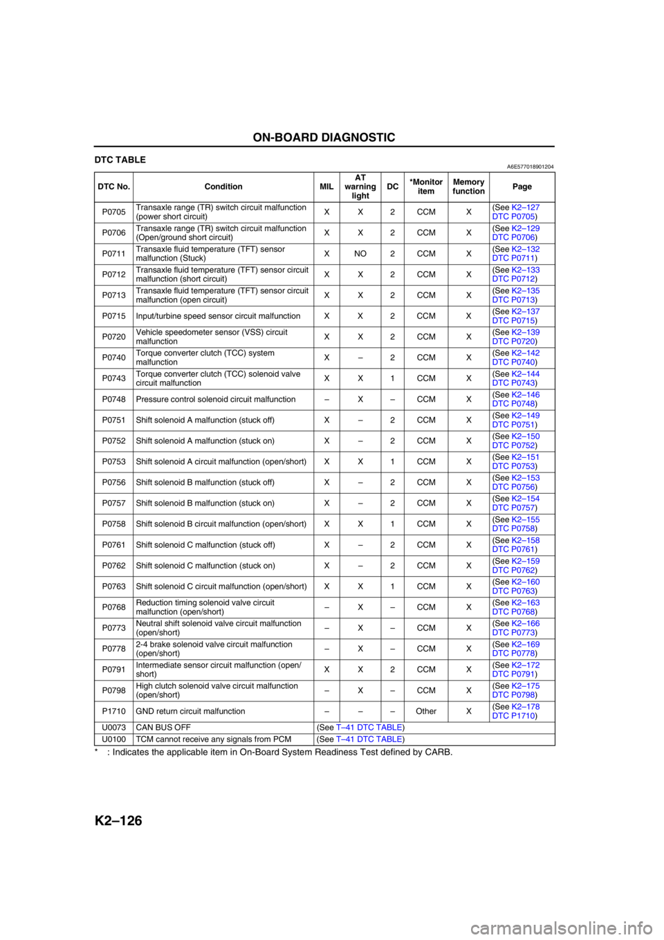
DTC TABLEA6E577018901204
* : Indicates the applicable item in On-Board System Readiness Test defined by CARB.
End Of Sie
DTC No. Condition MILAT
warning
lightDC*Monitor
itemMemory
functionPage
P0705Transaxle range (TR) switch circuit malfunction
(power short circuit)XX2CCM X(See K2–127
DTC P0705)
P0706Transaxle range (TR) switch circuit malfunction
(Open/ground short circuit)XX2CCM X(See K2–129
DTC P0706)
P0711Transaxle fluid temperature (TFT) sensor
malfunction (Stuck)XNO2CCM X(See K2–132
DTC P0711)
P0712Transaxle fluid temperature (TFT) sensor circuit
malfunction (short circuit)XX2CCM X(See K2–133
DTC P0712)
P0713Transaxle fluid temperature (TFT) sensor circuit
malfunction (open circuit)XX2CCM X(See K2–135
DTC P0713)
P0715 Input/turbine speed sensor circuit malfunction X X 2 CCM X(See K2–137
DTC P0715)
P0720Vehicle speedometer sensor (VSS) circuit
malfunctionXX2CCM X(See K2–139
DTC P0720)
P0740Torque converter clutch (TCC) system
malfunctionX–2CCM X(See K2–142
DTC P0740)
P0743Torque converter clutch (TCC) solenoid valve
circuit malfunctionXX1CCM X(See K2–144
DTC P0743)
P0748 Pressure control solenoid circuit malfunction–X–CCM X(See K2–146
DTC P0748)
P0751 Shift solenoid A malfunction (stuck off) X–2CCM X(See K2–149
DTC P0751)
P0752 Shift solenoid A malfunction (stuck on) X–2CCM X(See K2–150
DTC P0752)
P0753 Shift solenoid A circuit malfunction (open/short) X X 1 CCM X(See K2–151
DTC P0753)
P0756 Shift solenoid B malfunction (stuck off) X–2CCM X(See K2–153
DTC P0756)
P0757 Shift solenoid B malfunction (stuck on) X–2CCM X(See K2–154
DTC P0757)
P0758 Shift solenoid B circuit malfunction (open/short) X X 1 CCM X(See K2–155
DTC P0758)
P0761 Shift solenoid C malfunction (stuck off) X–2CCM X(See K2–158
DTC P0761)
P0762 Shift solenoid C malfunction (stuck on) X–2CCM X(See K2–159
DTC P0762)
P0763 Shift solenoid C circuit malfunction (open/short) X X 1 CCM X(See K2–160
DTC P0763)
P0768Reduction timing solenoid valve circuit
malfunction (open/short)–X–CCM X(See K2–163
DTC P0768)
P0773Neutral shift solenoid valve circuit malfunction
(open/short)–X–CCM X(See K2–166
DTC P0773)
P07782-4 brake solenoid valve circuit malfunction
(open/short)–X–CCM X(See K2–169
DTC P0778)
P0791Intermediate sensor circuit malfunction (open/
short)XX2CCM X(See K2–172
DTC P0791)
P0798High clutch solenoid valve circuit malfunction
(open/short)–X–CCM X(See K2–175
DTC P0798)
P1710 GND return circuit malfunction–––Other X(See K2–178
DTC P1710)
U0073 CAN BUS OFF (See T–41 DTC TABLE)
U0100 TCM cannot receive any signals from PCM (See T–41 DTC TABLE)
Page 584 of 909

ON-BOARD DIAGNOSTIC
K2–169
K2
DTC P0778A6E577018901226
DTC P0778 2-4 brake solenoid valve circuit malfunction (open/short)
DETECTION
CONDITION•Open or short in 2-4 brake solenoid signal system (while TCM monitors solenoid output voltage, the
voltage that differs from the ON/OFF signal output by CPU in TCM is detected).
Diagnostic support note:
•This is continuous monitor (CCM).
•MIL does not illuminates.
•PENDING CODE is not available.
•FREEZE FRAME DATA is not available.
•AT warning light indication.
•DTC is stored in TCM memory.
POSSIBLE
CAUSE•Open circuit between 2-4 brake solenoid valve terminal A and TCM terminal 2V
•Short to ground between 2-4 brake solenoid valve terminal A and TCM terminal 2V
•Short to power between 2-4 brake solenoid valve terminal A and TCM terminal 2V
•2-4 brake solenoid valve malfunction
•Damaged connector between 2-4 brake solenoid valve and TCM
•TCM malfunction
CPU
CPU2V
A
D
A
A J 2PB TCM
AT X
TCM
HARNESS SIDE CONNECTORTERMINAL COMPONENT
NO.1(12-PIN)
HARNESS SIDE CONNECTOR
COUPLER COMPONENT
(10-PIN)
PART SIDE CONNECTOR2-4 BRAKE
SOLENOID VALVE
2-4 BRAKE
SOLENOID VALVE
HARNESS SIDE CONNECTOR
Page 598 of 909

TROUBLESHOOTING
K2–183
K2
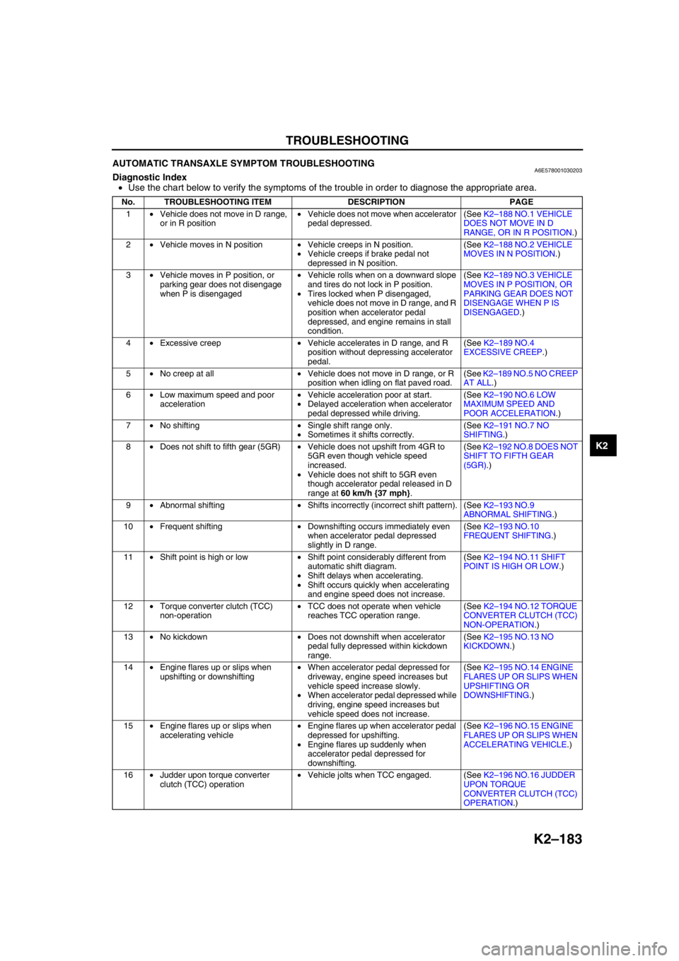
AUTOMATIC TRANSAXLE SYMPTOM TROUBLESHOOTINGA6E578001030203Diagnostic Index
•Use the chart below to verify the symptoms of the trouble in order to diagnose the appropriate area.
No. TROUBLESHOOTING ITEM DESCRIPTION PAGE
1•Vehicle does not move in D range,
or in R position•Vehicle does not move when accelerator
pedal depressed.(See K2–188 NO.1 VEHICLE
DOES NOT MOVE IN D
RANGE, OR IN R POSITION.)
2•Vehicle moves in N position•Vehicle creeps in N position.
•Vehicle creeps if brake pedal not
depressed in N position.(See K2–188 NO.2 VEHICLE
MOVES IN N POSITION.)
3•Vehicle moves in P position, or
parking gear does not disengage
when P is disengaged•Vehicle rolls when on a downward slope
and tires do not lock in P position.
•Tires locked when P disengaged,
vehicle does not move in D range, and R
position when accelerator pedal
depressed, and engine remains in stall
condition.(See K2–189 NO.3 VEHICLE
MOVES IN P POSITION, OR
PARKING GEAR DOES NOT
DISENGAGE WHEN P IS
DISENGAGED.)
4•Excessive creep•Vehicle accelerates in D range, and R
position without depressing accelerator
pedal.(See K2–189 NO.4
EXCESSIVE CREEP.)
5•No creep at all•Vehicle does not move in D range, or R
position when idling on flat paved road.(See K2–189 NO.5 NO CREEP
AT ALL.)
6•Low maximum speed and poor
acceleration•Vehicle acceleration poor at start.
•Delayed acceleration when accelerator
pedal depressed while driving.(See K2–190 NO.6 LOW
MAXIMUM SPEED AND
POOR ACCELERATION.)
7•No shifting•Single shift range only.
•Sometimes it shifts correctly.(See K2–191 NO.7 NO
SHIFTING.)
8•Does not shift to fifth gear (5GR)•Vehicle does not upshift from 4GR to
5GR even though vehicle speed
increased.
•Vehicle does not shift to 5GR even
though accelerator pedal released in D
range at 60 km/h {37 mph}.(See K2–192 NO.8 DOES NOT
SHIFT TO FIFTH GEAR
(5GR).)
9•Abnormal shifting•Shifts incorrectly (incorrect shift pattern). (See K2–193 NO.9
ABNORMAL SHIFTING.)
10•Frequent shifting•Downshifting occurs immediately even
when accelerator pedal depressed
slightly in D range.(See K2–193 NO.10
FREQUENT SHIFTING.)
11•Shift point is high or low•Shift point considerably different from
automatic shift diagram.
•Shift delays when accelerating.
•Shift occurs quickly when accelerating
and engine speed does not increase.(See K2–194 NO.11 SHIFT
POINT IS HIGH OR LOW.)
12•Torque converter clutch (TCC)
non-operation•TCC does not operate when vehicle
reaches TCC operation range.(See K2–194 NO.12 TORQUE
CONVERTER CLUTCH (TCC)
NON-OPERATION.)
13•No kickdown•Does not downshift when accelerator
pedal fully depressed within kickdown
range.(See K2–195 NO.13 NO
KICKDOWN.)
14•Engine flares up or slips when
upshifting or downshifting•When accelerator pedal depressed for
driveway, engine speed increases but
vehicle speed increase slowly.
•When accelerator pedal depressed while
driving, engine speed increases but
vehicle speed does not increase.(See K2–195 NO.14 ENGINE
FLARES UP OR SLIPS WHEN
UPSHIFTING OR
DOWNSHIFTING.)
15•Engine flares up or slips when
accelerating vehicle•Engine flares up when accelerator pedal
depressed for upshifting.
•Engine flares up suddenly when
accelerator pedal depressed for
downshifting.(See K2–196 NO.15 ENGINE
FLARES UP OR SLIPS WHEN
ACCELERATING VEHICLE.)
16•Judder upon torque converter
clutch (TCC) operation•Vehicle jolts when TCC engaged. (See K2–196 NO.16 JUDDER
UPON TORQUE
CONVERTER CLUTCH (TCC)
OPERATION.)
Page 599 of 909

K2–184
TROUBLESHOOTING
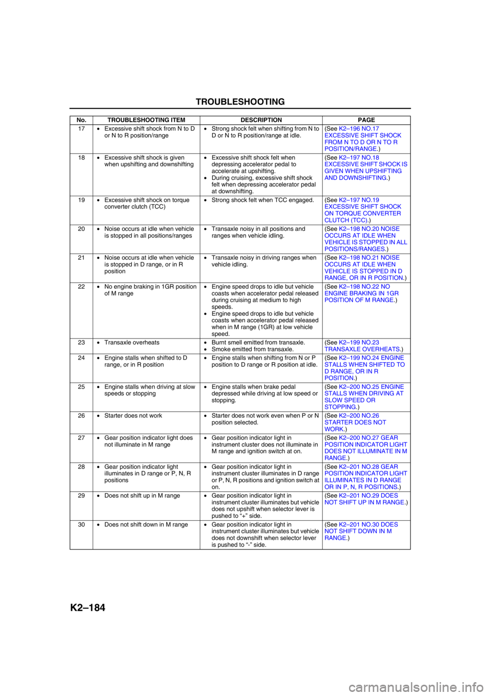
17•Excessive shift shock from N to D
or N to R position/range•Strong shock felt when shifting from N to
D or N to R position/range at idle.(See K2–196 NO.17
EXCESSIVE SHIFT SHOCK
FROM N TO D OR N TO R
POSITION/RANGE.)
18•Excessive shift shock is given
when upshifting and downshifting•Excessive shift shock felt when
depressing accelerator pedal to
accelerate at upshifting.
•During cruising, excessive shift shock
felt when depressing accelerator pedal
at downshifting.(See K2–197 NO.18
EXCESSIVE SHIFT SHOCK IS
GIVEN WHEN UPSHIFTING
AND DOWNSHIFTING.)
19•Excessive shift shock on torque
converter clutch (TCC)•Strong shock felt when TCC engaged. (See K2–197 NO.19
EXCESSIVE SHIFT SHOCK
ON TORQUE CONVERTER
CLUTCH (TCC).)
20•Noise occurs at idle when vehicle
is stopped in all positions/ranges•Transaxle noisy in all positions and
ranges when vehicle idling.(See K2–198 NO.20 NOISE
OCCURS AT IDLE WHEN
VEHICLE IS STOPPED IN ALL
POSITIONS/RANGES.)
21•Noise occurs at idle when vehicle
is stopped in D range, or in R
position•Transaxle noisy in driving ranges when
vehicle idling.(See K2–198 NO.21 NOISE
OCCURS AT IDLE WHEN
VEHICLE IS STOPPED IN D
RANGE, OR IN R POSITION.)
22•No engine braking in 1GR position
of M range•Engine speed drops to idle but vehicle
coasts when accelerator pedal released
during cruising at medium to high
speeds.
•Engine speed drops to idle but vehicle
coasts when accelerator pedal released
when in M range (1GR) at low vehicle
speed.(See K2–198 NO.22 NO
ENGINE BRAKING IN 1GR
POSITION OF M RANGE.)
23•Transaxle overheats•Burnt smell emitted from transaxle.
•Smoke emitted from transaxle.(See K2–199 NO.23
TRANSAXLE OVERHEATS.)
24•Engine stalls when shifted to D
range, or in R position•Engine stalls when shifting from N or P
position to D range or R position at idle.(See K2–199 NO.24 ENGINE
STALLS WHEN SHIFTED TO
D RANGE, OR IN R
POSITION.)
25•Engine stalls when driving at slow
speeds or stopping•Engine stalls when brake pedal
depressed while driving at low speed or
stopping.(See K2–200 NO.25 ENGINE
STALLS WHEN DRIVING AT
SLOW SPEED OR
STOPPING.)
26•Starter does not work•Starter does not work even when P or N
position selected.(See K2–200 NO.26
STARTER DOES NOT
WORK.)
27•Gear position indicator light does
not illuminate in M range•Gear position indicator light in
instrument cluster does not illuminate in
M range and ignition switch at on.(See K2–200 NO.27 GEAR
POSITION INDICATOR LIGHT
DOES NOT ILLUMINATE IN M
RANGE.)
28•Gear position indicator light
illuminates in D range or P, N, R
positions•Gear position indicator light in
instrument cluster illuminates in D range
or P, N, R positions and ignition switch at
on.(See K2–201 NO.28 GEAR
POSITION INDICATOR LIGHT
ILLUMINATES IN D RANGE
OR IN P, N, R POSITIONS.)
29•Does not shift up in M range•Gear position indicator light in
instrument cluster illuminates but vehicle
does not upshift when selector lever is
pushed to “+” side.(See K2–201 NO.29 DOES
NOT SHIFT UP IN M RANGE.)
30•Does not shift down in M range•Gear position indicator light in
instrument cluster illuminates but vehicle
does not downshift when selector lever
is pushed to “-” side.(See K2–201 NO.30 DOES
NOT SHIFT DOWN IN M
RANGE.) No. TROUBLESHOOTING ITEM DESCRIPTION PAGE
Page 601 of 909

K2–186
TROUBLESHOOTING
CAN signal
Vehicle dose not move in D range, or in R position
X
XXX X
X
X X
X
XX
X
X
X
X
X
XX
XX
XX
XXX
XX
XX
X
XXX X
XX X
XX X
XX X
XXX
XX
X
XX
X XX XX
X
XX
XX
X XX
X XXXX
XXXX
XXXXX XX XXX
X
X
XX
X
X
X
X
X
X
X
X
X
X X
X
X
X X
XXX
XX
XX X X
X 1
Excessive creep 4
No creep at all 5
Low maximum speed and poor acceleration 6
No shifting 7
Does not shift to fifth gear (5GR) 8
Abnormal shifting 9
Frequent shifting 10
Shift point is high or low 11
Torque converter clutch (TCC) non-operation 12
No kickdown 13
Engine flares up or slips when upshifting or downshifting 14
Engine flares up or slip when accelerating vehicle 15
Judder upon torque converter clutch (TCC) operation 16
Excessive shift shock from N to D or N to R position/range 17
Excessive shift shock on torque converter clutch (TCC) 19
No engine braking in 1GR position of M range 22
Transaxle overheats 23
Engine stalls when shifted to D range, or in R position 24
Engine stalls when driving at slow speeds or stopping 25
Starter does not work 26Excessive shift shock is given when upshifting and
downshifting 18
Noise occurs at idle when vehicle is stopped in all
positions/ranges 20
Noise occurs at idle when vehicle is stopped in D
range, or in R position 21
Gear position indicator light illuminates in D range or P, N,
R positions 28Gear position indicator light does not illuminate in M range
Electrical system components
ATX inner parts
ATX outer parts
Hydraulic system
components
Control valve body 27
Does not shift up in M range
29
Does not shift down in M rangeSymptom item
Cause of trouble
Open/short
Malfunction signal is inputed Signal is inputed
Open/short
Open/short Open/short
Open/short
Open/short
Open/short
Open/short
Open/short Open/short
Open/short
Open/short Open/short
Control valve spool is not operating properly ATF amount
2-4 brake accumulator is not operating properly Low clutch solenoid accumulator is not operating properly
Direct clutch accumulator is not operating properly High clutch accumulator is not operating properly2-4 brake solenoid valve Pressure control solenoid
TCC solenoid valve
High clutch solenoid valve TFT sensor N-D select
Transaxle range switch
Power supply, GND
Shift solenoid A
Shift solenoid B
Shift solenoid C
Neutral shift solenoid valve
Reducation timing solenoid
GND return line
30Vehicle moves in N position 2
Vehicle moves in P position, or parking gear does not
disengage when P is disengaged 3
A6E5780W002