warning light MAZDA 6 2002 Suplement Repair Manual
[x] Cancel search | Manufacturer: MAZDA, Model Year: 2002, Model line: 6, Model: MAZDA 6 2002Pages: 909, PDF Size: 17.16 MB
Page 646 of 909
M–16
ELECTRONIC 4WD CONTROL SYSTEM
ON-BOARD DIAGNOSTICA6E632227100208Outline
•The on-board diagnostic function allows for detecting malfunctions in the input/output signals when the ignition
key is at the ON position.
•The DLC-2, which combines the failure detection and detection maintenance connectors, has been adopted to
improve serviceability. By connecting a WDS or equivalent to the DLC-2, malfunction diagnosis can be carried
out.
•Using a WDS or equivalent DTCs can be retrieved or erased, depending on the screen display, thus improving
serviceability.
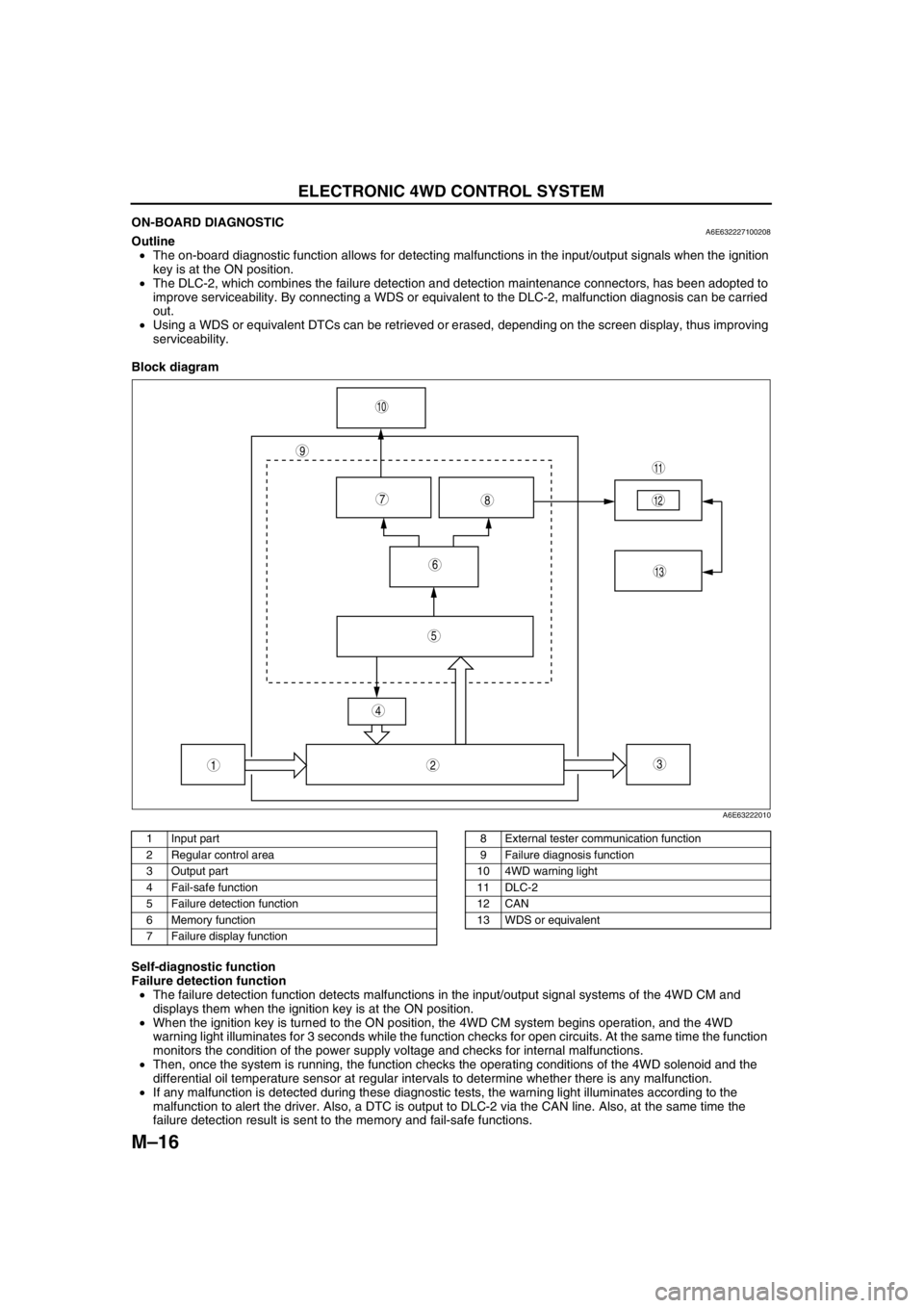
Block diagram
.
Self-diagnostic function
Failure detection function
•The failure detection function detects malfunctions in the input/output signal systems of the 4WD CM and
displays them when the ignition key is at the ON position.
•When the ignition key is turned to the ON position, the 4WD CM system begins operation, and the 4WD
warning light illuminates for 3 seconds while the function checks for open circuits. At the same time the function
monitors the condition of the power supply voltage and checks for internal malfunctions.
•Then, once the system is running, the function checks the operating conditions of the 4WD solenoid and the
differential oil temperature sensor at regular intervals to determine whether there is any malfunction.
•If any malfunction is detected during these diagnostic tests, the warning light illuminates according to the
malfunction to alert the driver. Also, a DTC is output to DLC-2 via the CAN line. Also, at the same time the
failure detection result is sent to the memory and fail-safe functions.
9
87
5
4
3
10
13
11
12
6
12
A6E63222010
1 Input part
2 Regular control area
3 Output part
4 Fail-safe function
5 Failure detection function
6 Memory function
7 Failure display function8 External tester communication function
9 Failure diagnosis function
10 4WD warning light
11 DLC-2
12 CAN
13 WDS or equivalent
Page 647 of 909

ELECTRONIC 4WD CONTROL SYSTEM
M–17
M
Memory function
•This function stores DTCs for malfunctions of the input/output signal systems as determined by the failure
detection function. Once a DTC is stored, it is not cleared even if the input/output signal system malfunction
returns to normal when the ignition key is turned to the LOCK position (engine OFF).
•Since DTCs are stored in the non-volatile memory inside the 4WD CM, they are not cleared even if the battery
is disconnected. Therefore, it is necessary to clear the memory when maintenance has been completed. For
clearing DTCs, refer to the procedures in the Workshop Manual.
•When inspecting DTCs using a WDS or equivalent, only one memory stored DTC at a time can be displayed.
Therefore, when multiple DTCs have been stored, it is necessary to inspect for DTCs again after repairing and
clearing the present DTC to ensure that there are no more DTCs present in the memory.
Fail-safe function
•When the failure detection function determines that there is a malfunction, the 4WD warning light illuminates to
alert the driver. At this time, the fail-safe function suspends control or takes other measures to ensure that
driving stability is not lost.
X:Available
*1: Does not illuminate when only the coupling torque request signal from the DSC HU/CM cannot be received.*2: Only integrated DSC control is prohibited when only the coupling torque request signal from the DSC HU/CM
cannot be received.
External tester communication function
•This function allows for the storing and clearing of DTCs due to a communication link between the 4WD CM
and an external tester.
End Of Sie
DTC Malfunction location4WD warning
lightconditionDTC stored in
memoryControl condition
P1887 System wiring Illuminated X Stop
P1888 Differential oil temperature sensor Illuminated X Stop
U0100 PCM communication system Illuminated X Stop
U0101 TCM communication system Illuminated X Stop
U0121 DSC communication system
Illuminated
*1X
Stop*2
Page 737 of 909
P–4
ABS/TCS
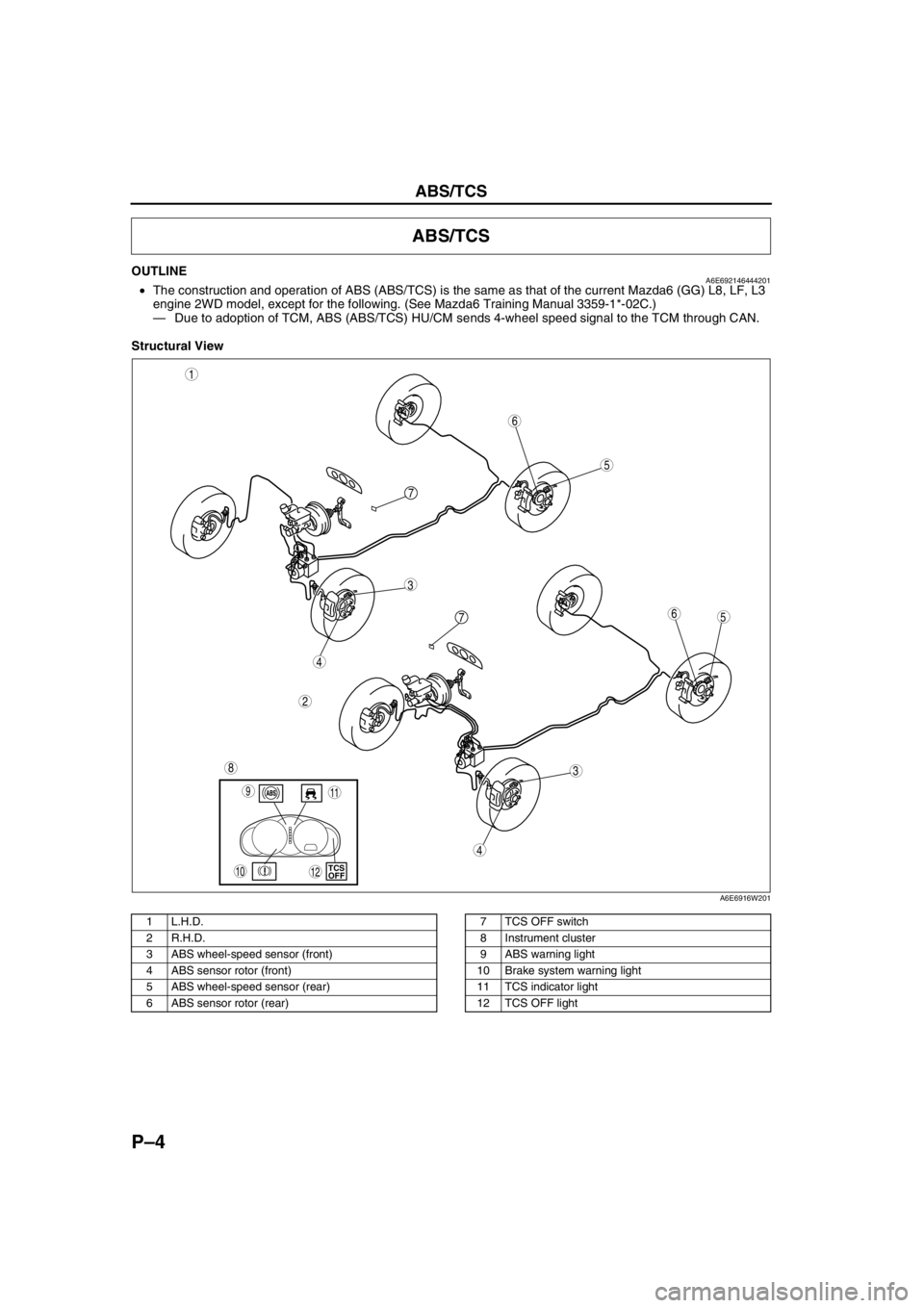
OUTLINEA6E692146444201•The construction and operation of ABS (ABS/TCS) is the same as that of the current Mazda6 (GG) L8, LF, L3
engine 2WD model, except for the following. (See Mazda6 Training Manual 3359-1*-02C.)
—Due to adoption of TCM, ABS (ABS/TCS) HU/CM sends 4-wheel speed signal to the TCM through CAN.
Structural View
.
ABS/TCS
5
3
1
2
6
7
5
3
6
8
4
4
7
9
10TCS
OFF
11
12
A6E6916W201
1 L.H.D.
2 R.H.D.
3 ABS wheel-speed sensor (front)
4 ABS sensor rotor (front)
5 ABS wheel-speed sensor (rear)
6 ABS sensor rotor (rear)7 TCS OFF switch
8 Instrument cluster
9 ABS warning light
10 Brake system warning light
11 TCS indicator light
12 TCS OFF light
Page 738 of 909

ABS/TCS
P–5
P
System Diagram
.
End Of Sie
9
9
8
7
5
43
12
6
18
17
15
16
14
13
11
12
RF
FL
RR
RL
PCMG
E
FI Z
U
D
A
B
C
Y
AC
X
V O
R ADAB AA
ABS/TCS HU/CM
pP
9
10
19
920
A6E6921W201
1 IG switch
2SUS 15 A fuse
3 ABS 60 A fuse
4 Meter
5 ABS warning light
6 Brake system warning light
7 TCS OFF light
8 TCS indicator light
9CAN driver
10 Brake light11 Cruise actuator
12 TCS OFF switch
13 DLC-2
14 CAN-H
15 CAN-L
16 ABS Wheel-speed sensor
17 Battery
18 Brake switch
19 Audio unit, Wiper and washer switch, Car-navigation
unit, Auto leveling control unit
20 TCM, 4WD CM
Page 739 of 909
P–6
DYNAMIC STABILITY CONTROL
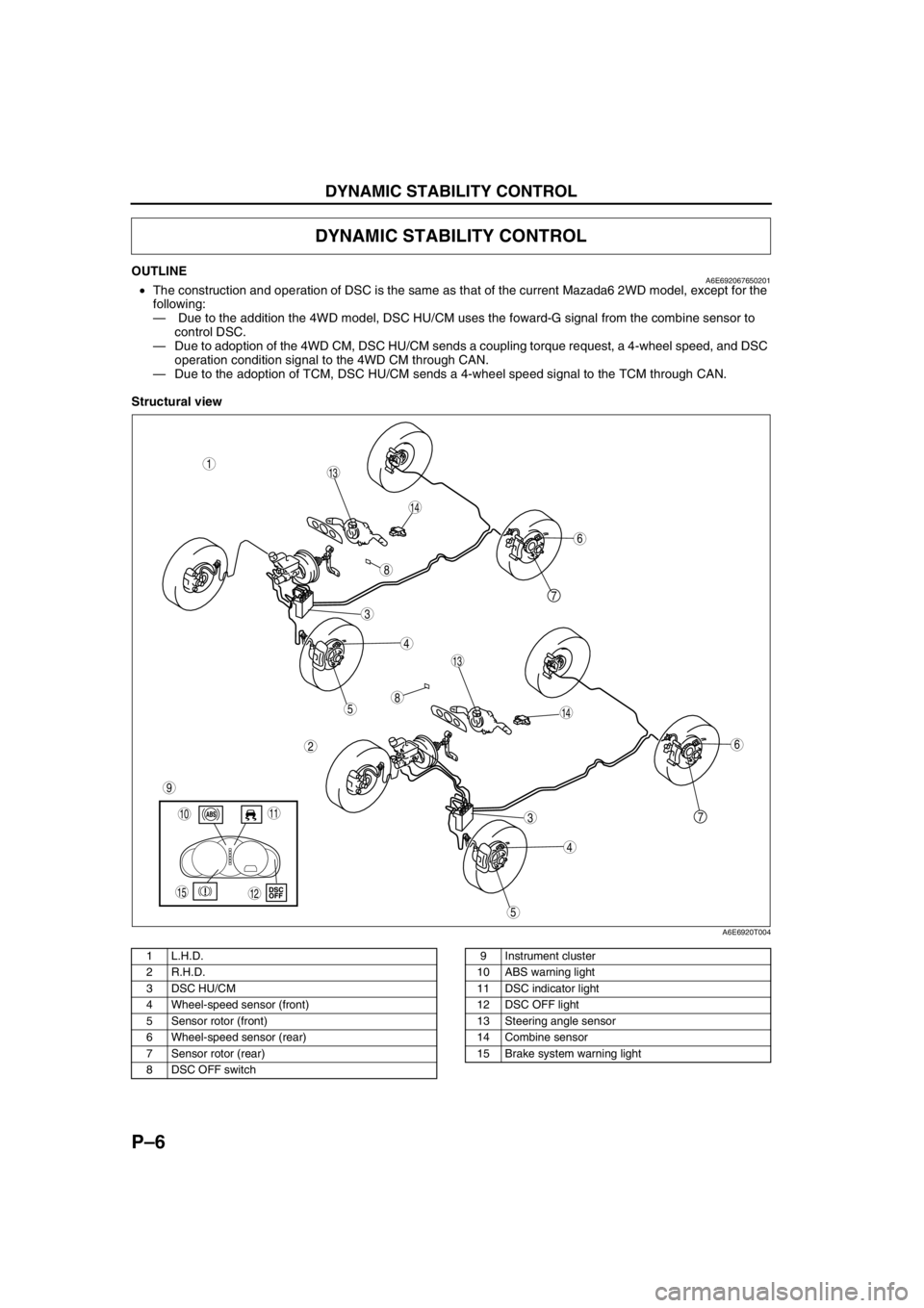
OUTLINEA6E692067650201•The construction and operation of DSC is the same as that of the current Mazada6 2WD model, except for the
following:
— Due to the addition the 4WD model, DSC HU/CM uses the foward-G signal from the combine sensor to
control DSC.
—Due to adoption of the 4WD CM, DSC HU/CM sends a coupling torque request, a 4-wheel speed, and DSC
operation condition signal to the 4WD CM through CAN.
—Due to the adoption of TCM, DSC HU/CM sends a 4-wheel speed signal to the TCM through CAN.
Structural view
.
DYNAMIC STABILITY CONTROL
7
5
4
3
1
2
14
13
6
13
12
5
4
3
7
6
1011
9
14
8
8
15
A6E6920T004
1 L.H.D.
2 R.H.D.
3 DSC HU/CM
4 Wheel-speed sensor (front)
5 Sensor rotor (front)
6 Wheel-speed sensor (rear)
7 Sensor rotor (rear)
8 DSC OFF switch9 Instrument cluster
10 ABS warning light
11 DSC indicator light
12 DSC OFF light
13 Steering angle sensor
14 Combine sensor
15 Brake system warning light
Page 740 of 909

DYNAMIC STABILITY CONTROL
P–7
P
Wiring Diagram
.
9
RF
FL
RR
RL
PCM
G
E
M
I
F
K
H
Q
NJ
P
S
T
V
O
Y
X
W
U
R
L
Z
AC
D
B
AG
AF
AE
AC
AA
AB
C
F
D
A
B
EDSC HU/CM
A
B
C
D
F
1
3
2
8
7
5
4
6
9
9
9
10
11
13
12
15
14
18
17
16
1920
2122
24
23
A6E6921W203
1 IG switch
2SUS 15A fuse
3 ABS 60 A fuse
4 Meter
5 ABS warning light
6 Brake system warning light
7 DSC OFF light
8 DSC indicator light
9CAN driver
10 Battery
11 Cruise actuator
12 DSC OFF switch13 DLC-2
14 CAN-H
15 CAN-L
16 Wheel-speed sensor
17 Combine sensor
18 Steering angle sensor
19 Brake switch
20 Brake light
21 Back-up light switch (MTX only)
22 Back-up light (MTX only)
23 Audio unit, Wiper and washer switch, Car-navigation
unit, Auto leveling control unit
24 TCM, 4WD CM
Page 742 of 909

ON-BOARD DIAGNOSTIC
P–9
P
OUTLINEA6E697043000201•The operation of the on-board diagnostic system for ABS (ABS/TCS) or DSC is the same as that of the current
Mazda6 (GG) L8, LF, L3 engine 2WD model, except for the following. (See Mazda6 Training Manual
3359-1*-02C.)
— Due to the addition of the 4WD model, DTCs and PID data monitor has been added.
—Due to the addition of the MZR-CD (RF Turbo) engine model, the DTC C1119 fail-safe function and the
detection condition have been changed.
Fail-safe Function
Fail-safe function table
*1: When engine speed signal through CAN is out of specification, the light illuminates.*2: When engine speed signal through CAN is out of specification, the system is suspended.*3: When engine speed signal value through CAN is invalid, only brake TCS is available.*4: When fuel injection information through CAN is out of specification or invalid, only brake TCS is available.*5: When engine speed signal value through CAN is invalid, only brake DSC is available.*6: When the engine control system has a malfunction, only brake DSC is available.
PID/DATA Monitor Table
End Of Sie
ON-BOARD DIAGNOSTIC
Malfunc-
tion
locationDTC Fail-safe function
WDS
or
equiva-
lentWarning light illumination condition Control condition
ABS
warning
lightBRAKE
system
warning
light
(when
parking
brake is
released)DSC
(TCS)
OFF lightDSC
(TCS)
indicator
light ABS
controlEBD
controlTCS
controlDSC
controlBrake
assist
control
PCM and/
or engine
speed
signal lineC1119Not
Illuminated Not
Illuminated Not
Illuminated
*1Illuminated Available AvailableAvailable*2, *3, *4Available*2, *5, *6Available
Combine
sensor
(forward-
G) lineC1949
Illuminated Not
Illuminated Illuminated IlluminatedNot
availableAvailable—Not
availableNot
available
C1950
CAN line U2511Not
Illuminated Not
Illuminated Not
Illuminated Illuminated Available Available—Available Available
PID name input/output part Operation/unit
ACCLMTR Accelerometer ACCELERATION
Page 744 of 909
CONVENTIONAL BRAKE SYSTEM
P–11
P
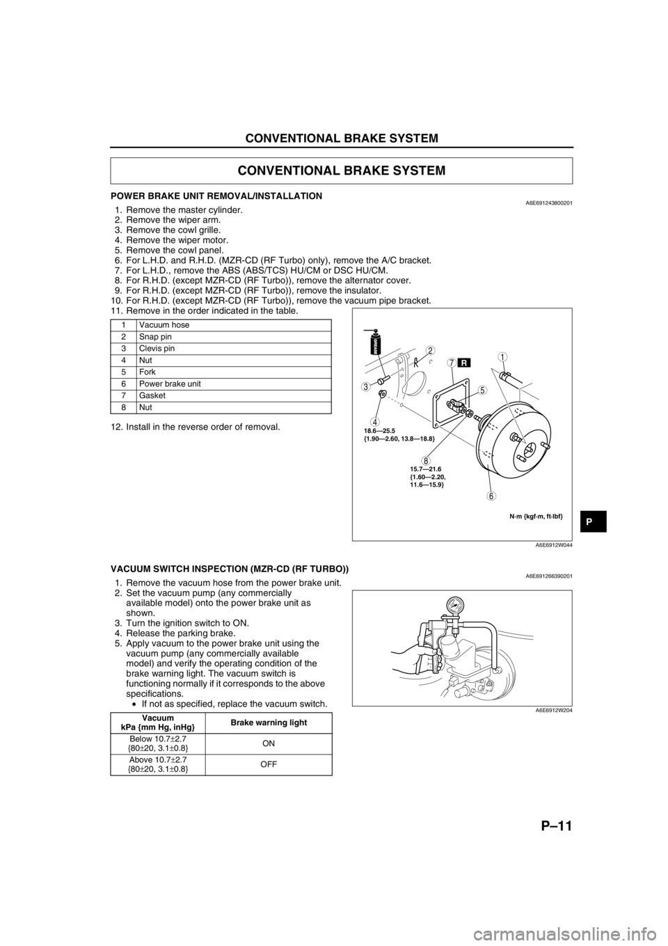
POWER BRAKE UNIT REMOVAL/INSTALLATIONA6E6912438002011. Remove the master cylinder.
2. Remove the wiper arm.
3. Remove the cowl grille.
4. Remove the wiper motor.
5. Remove the cowl panel.
6. For L.H.D. and R.H.D. (MZR-CD (RF Turbo) only), remove the A/C bracket.
7. For L.H.D., remove the ABS (ABS/TCS) HU/CM or DSC HU/CM.
8. For R.H.D. (except MZR-CD (RF Turbo)), remove the alternator cover.
9. For R.H.D. (except MZR-CD (RF Turbo)), remove the insulator.
10. For R.H.D. (except MZR-CD (RF Turbo)), remove the vacuum pipe bracket.
11. Remove in the order indicated in the table.
12. Install in the reverse order of removal.
End Of Sie
VACUUM SWITCH INSPECTION (MZR-CD (RF TURBO))A6E6912663902011. Remove the vacuum hose from the power brake unit.
2. Set the vacuum pump (any commercially
available model) onto the power brake unit as
shown.
3. Turn the ignition switch to ON.
4. Release the parking brake.
5. Apply vacuum to the power brake unit using the
vacuum pump (any commercially available
model) and verify the operating condition of the
brake warning light. The vacuum switch is
functioning normally if it corresponds to the above
specifications.
•If not as specified, replace the vacuum switch.
End Of Sie
CONVENTIONAL BRAKE SYSTEM
1 Vacuum hose
2 Snap pin
3Clevis pin
4Nut
5Fork
6 Power brake unit
7Gasket
8Nut
GREASEGREASE
R
3
4
8
6
2
7
5
1
18.6—25.5
{1.90—2.60, 13.8—18.8}
N·m {kgf·m, ft·lbf}
15.7—21.6
{1.60—2.20,
11.6—15.9}
A6E6912W044
Vacuum
kPa {mm Hg, inHg}Brake warning light
Below 10.7±2.7
{80±20, 3.1±0.8}ON
Above 10.7±2.7
{80±20, 3.1±0.8}OFFA6E6912W204
Page 750 of 909
PARKING BRAKE SYSTEM, DYNAMIC STABILITY CONTROL
P–17
P
PARKING BRAKE (LEVER TYPE) ADJUSTMENTA6E6914440002011. Start the engine and depress the brake pedal several times.
2. Stop the engine.
3. For the 2WD model, remove the rear ashtray case behind the center console
4. For the 4WD model, remove the 4 screws (back side) and pull up the rear of the center console, then remove
the rear ashtray case.
5. Turn the adjusting nut as shown in the figure.
6. After adjustment, inspect the following points:
(1) Turn the ignition switch to ON, pull the parking
brake lever one notch, and verify that the
parking brake warning light illuminates.
(2) Verify that the rear brakes do not drag.
End Of Sie
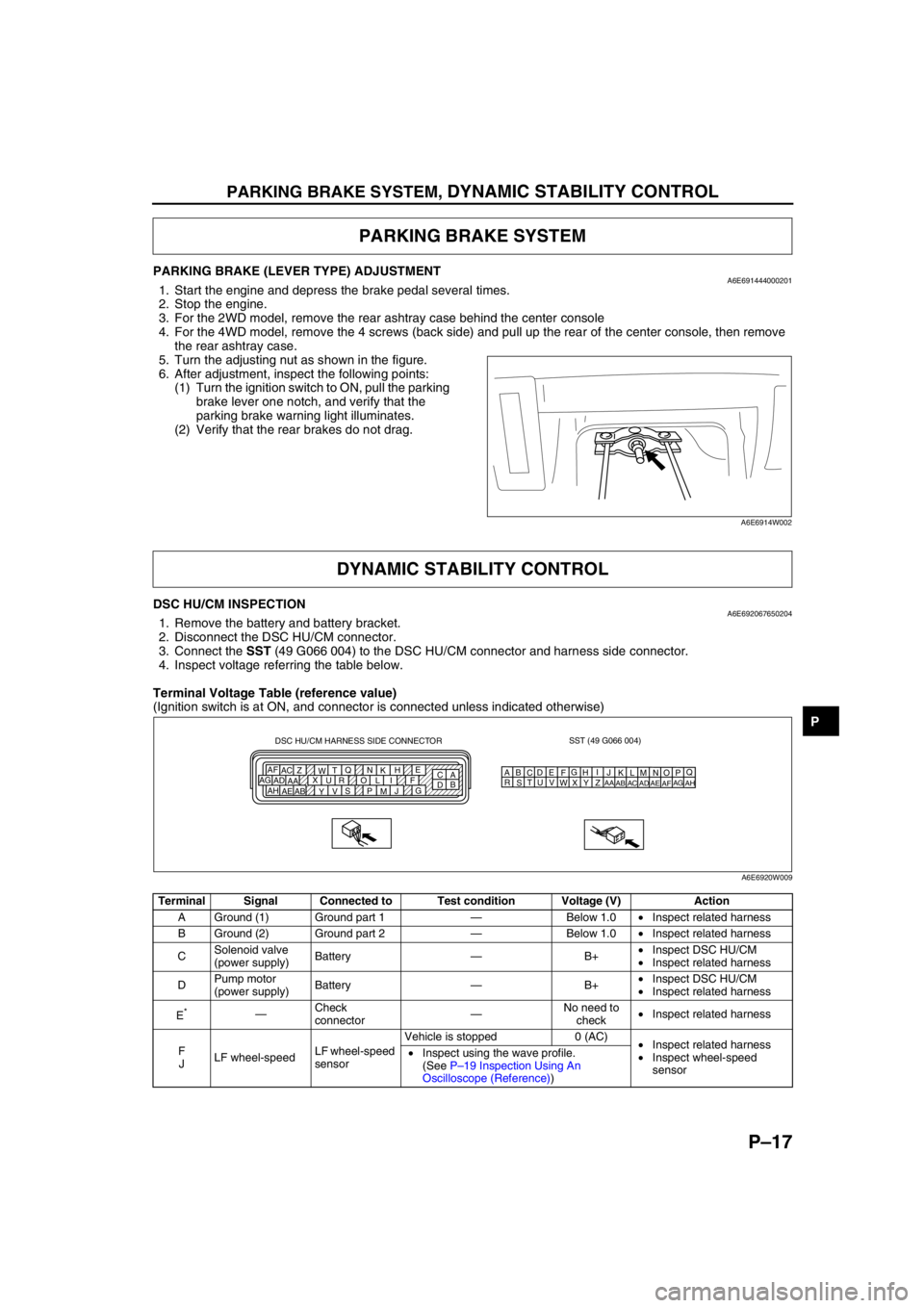
DSC HU/CM INSPECTIONA6E6920676502041. Remove the battery and battery bracket.
2. Disconnect the DSC HU/CM connector.
3. Connect the SST (49 G066 004) to the DSC HU/CM connector and harness side connector.
4. Inspect voltage referring the table below.
Terminal Voltage Table (reference value)
(Ignition switch is at ON, and connector is connected unless indicated otherwise)
PARKING BRAKE SYSTEM
A6E6914W002
DYNAMIC STABILITY CONTROL
Terminal Signal Connected to Test condition Voltage (V) Action
A Ground (1) Ground part 1—Below 1.0•Inspect related harness
B Ground (2) Ground part 2—Below 1.0•Inspect related harness
CSolenoid valve
(power supply)Battery—B+•Inspect DSC HU/CM
•Inspect related harness
DPump motor
(power supply)Battery—B+•Inspect DSC HU/CM
•Inspect related harness
E
*—Check
connector—No need to
check•Inspect related harness
F
JLF wheel-speedLF wheel-speed
sensorVehicle is stopped 0 (AC)
•Inspect related harness
•Inspect wheel-speed
sensor •Inspect using the wave profile.
(See P–19 Inspection Using An
Oscilloscope (Reference))
SST (49 G066 004)
AQ
B
CDE
FG
HI
J DSC HU/CM HARNESS SIDE CONNECTOR
A
C E
H
K N Q
T
W Z AC AF
F I L O R U X
AA AD AG
G
J
M P S
V
Y AB AE AHB
DKN
T
WZ
AC
AFLO
RU
XAA
ADAGMP
SV
YAB
AEAH
A6E6920W009
Page 756 of 909

ON-BOARD DIAGNOSTIC
P–23
P
PMPSTAT
(Pump motor output state)ON/OFF•Pump motor is activated:
ON
•Pump motor is deactivated:
OFFInspect DSC HU/CM
—
BRK_FLUID (with DSC only)
(Brake fluid level sensor input)OK/LOW•Brake fluid is above LOW:
OK
•Brake fluid is below LOW:
LOWInspect brake fluid
level.
Inspect brake fluid
level sensor.—
BOO_ABS
(Brake pedal switch input)ON/OFF•Brake pedal is depressed:
ON
•Brake pedal is released:
OFFInspect brake switch.
ABS (ABS/
TCS): Y
DSC: L
ABS_LAMP
(ABS warning light driver
output state)ON/OFF•ABS warning light is
illuminated: ON
•ABS warning light is not
illuminated: OFFInspect ABS warning
light.
—
BRAKE_LMP
(BRAKE system warning light
output state)ON/OFF•BRAKE system warning
light is illuminated: ON
•BRAKE system warning
light is not illuminated: OFFInspect BRAKE
system warning light.
—
ABSRR_O
(Right rear ABS pressure
reduction solenoid valve
output state)ON/OFF•During ABS control: ON/
OFF
(solenoid valve is activated/
deactivated)
•Not ABS control: OFF
(solenoid valve is
deactivated)Internal fault of ABS
(ABS/TCS) or DSC
HU/CM. Replace ABS
(ABS/TCS) or DSC
HU/CM.—
ABSLR_O
(Left rear ABS pressure
reduction solenoid valve
output state)ON/OFF•During ABS or EBD control:
ON/OFF
(solenoid valve is activated/
deactivated)
•Not ABS and EBD control:
OFF
(solenoid valve is
deactivated)Internal fault of ABS
(ABS/TCS) or DSC
HU/CM. Replace ABS
(ABS/TCS) or DSC
HU/CM.—
ABSRF_O
(Right front ABS pressure
reduction solenoid valve
output state)ON/OFF•During ABS control: ON/
OFF
(solenoid valve is activated/
deactivated)
•Not ABS control: OFF
(solenoid valve is
deactivated)Internal fault of ABS
(ABS/TCS) or DSC
HU/CM. Replace ABS
(ABS/TCS) or DSC
HU/CM.—
ABSLF_O
(Left front ABS pressure
reduction solenoid valve
output state)ON/OFF•During ABS control: ON/
OFF
(solenoid valve is activated/
deactivated)
•Not ABS control: OFF
(solenoid valve is
deactivated)Internal fault of ABS
(ABS/TCS) or DSC
HU/CM. Replace ABS
(ABS/TCS) or DSC
HU/CM.—
ABSRR_I
(Right rear ABS pressure
reduction solenoid valve
output state)ON/OFF•During ABS control: ON/
OFF
(solenoid valve is activated/
deactivated)
•Not ABS control: OFF
(solenoid valve is
deactivated)Internal fault of ABS
(ABS/TCS) or DSC
HU/CM. Replace ABS
(ABS/TCS) or DSC
HU/CM.—
ABSLR_I
(Left rear ABS pressure
retention solenoid valve output
state)ON/OFF•During ABS or EBD control:
ON/OFF
(solenoid valve is activated/
deactivated)
•Not ABS and EBD control:
OFF
(solenoid valve is
deactivated)Internal fault of ABS
(ABS/TCS) or DSC
HU/CM. Replace ABS
(ABS/TCS) or DSC
HU/CM.— PID Name
(Definition)Unit/Condition Condition/Specification ActionABS (ABS/
TCS) HU/CM or
DSC HU/CM
terminal