MAZDA 6 2002 Workshop Manual Suplement
Manufacturer: MAZDA, Model Year: 2002, Model line: 6, Model: MAZDA 6 2002Pages: 909, PDF Size: 17.16 MB
Page 751 of 909

P–18
DYNAMIC STABILITY CONTROL
K
HRR wheel-speedRR wheel-
speed sensorVehicle is stopped 0 (AC)
•Inspect related harness
•Inspect wheel-speed
sensor •Inspect using the wave profile.
(See P–19 Inspection Using An
Oscilloscope (Reference))
M
IRF wheel-speedRF wheel-
speed sensorVehicle is stopped 0 (AC)
•Inspect related harness
•Inspect wheel-speed
sensor •Inspect using the wave profile.
(See P–19 Inspection Using An
Oscilloscope (Reference))
Q
NLR wheel-speedLR wheel-speed
sensorVehicle is stopped 0 (AC)
•Inspect related harness
•Inspect wheel-speed
sensor •Inspect using the wave profile.
(See P–19 Inspection Using An
Oscilloscope (Reference))
G Battery (IG) Ignition switch Ignition switch ON B+•Inspect related harness
•Inspect ignition switch
L Brake switch Brake switchWhen brake pedal is
depressed10—14•Inspect related harness
•Inspect brake switch
OLateral-G
(lateral-G signal)Combine
sensorVehicle is stopped 2.2—2.8
•Inspect related harness
•Inspect combine sensor Left corneringFluctuation
between
2.5—4.0 V
Right corneringFluctuation
between
1.0—2.5 V
PCombine sensor
power outputCombine
sensorIgnition switch ON 4.75—5.25•Inspect related harness
•Inspect combine sensor
RSteering angle
(ground)Steering angle
sensor—Below 1.0•Inspect related harness
•Inspect steering angle
sensor
S Combine sensorCombine
sensor—3.5—5.0•Inspect related harness
•Inspect combine sensor
TYaw rate
(yaw rate signal)Combine
sensorVehicle is stopped 2.2—2.8
•Inspect related harness
•Inspect yaw rate sensor Right corneringFluctuation
between
2.5—4.62 V
Left corneringFluctuation
between
2.5—0.33 V
USteering angle
(neutral signal)Steering angle
sensorSteering position:
center position 25°—29°Below 1.0•Inspect related harness
•Inspect steering angle
sensor
Except above condition Approx. 4
VForward-G
(forward-G signal)Combine
sensorVehicle is stopped 2.2—2.8
•Inspect related harness
•Inspect combine sensor AccelerationFluctuation
between
2.5—4.0 V
Deceleration Fluctuation
between
1.0—2.5 V
WSteering angle
(steering angle
signal 2)Steering angle
sensor•Inspect using the wave profile.
(See P–19 Inspection Using An
Oscilloscope (Reference))•Inspect related harness
•Inspect steering angle
sensor
XSteering angle
(steering angle
signal 1)Steering angle
sensor•Inspect using the wave profile.
(See P–19 Inspection Using An
Oscilloscope (Reference))•Inspect related harness
•Inspect steering angle
sensor
YCombine sensor
(ground)Combine
sensor—Below 1.0•Inspect related harness
•Inspect combine sensor
AA DSC OFF switchDSC OFF
switchWhen switch is pressed Below 1.0
•Inspect related harness
•Inspect DSC OFF switch
When switch is not pressed B+
AB OBDKLN terminal of
DLC-2It cannot be determined with terminal
voltage whether the condition is good or bad
because advanced function diagnostic
output is performed with serial
communication. Inspect with service codes.•Inspect related harness
•Inspect DSC HU/CM Terminal Signal Connected to Test condition Voltage (V) Action
Page 752 of 909

DYNAMIC STABILITY CONTROL
P–19
P
*: Used for vehicle manufacturing, not used for DSC.
Inspection Using An Oscilloscope (Reference)
Steering angle (steering angle signal 1 and 2)
•DSC HU/CM terminal:
Steering angle signal 2: W (+) — R (-)
Steering angle signal 1: X (+) — R (-)
•Oscilloscope setting:
1 V/DIV (Y), 25 ms/DIV (X), DC range
•Vehicle condition: Rotating steering wheel at one
revolution per second
Note
•As steering wheel rotation speed increases,
period of wave shortens.
•As for shape of steering angle signals 1 and
2, the phase is different.
Wheel speed
•DSC HU/CM terminal:
RF: M (+) — I (-)
RR: K (+) — H (-)
LF: F (+) — J (-)
LR: Q (+) — N (-)
•Oscilloscope setting:
1 V/DIV (Y), 2 ms/DIV (X), AC range
•Vehicle condition: Driving 30 km/h (18.6 mph)
Note
•As vehicle speed increases, period of wave
shortens.
•If there is malfunctioning in the sensor rotor,
wave profile warps.
ACAuto cruise set
signal outputAuto cruise unitWhen auto cruise is ON Below 1.0
•Inspect related harness
•Inspect DSC HU/CM
When auto cruise is OFF B+
AD—— — — —
AEVehicle speed
output•Audio unit
•Wiper and
washer
switch
•Car-navigatio
n unit
•Auto
leveling
control unit
•Cruise
actuatorVehicle is stopped 0
•Inspect related harness
•Inspect front wheel-speed
sensor •Inspect using the wave profile.
(See P–19 Inspection Using An
Oscilloscope (Reference))
AF CAN-L——No need to
check—
AG CAN-H——No need to
check—
AH—— — — — Terminal Signal Connected to Test condition Voltage (V) Action
0 V
A6E6921W014
0 V
A6E6921W013
Page 753 of 909

P–20
DYNAMIC STABILITY CONTROL
Vehicle speed output
•DSC HU/CM terminal: AE (+) — A(-)
•Oscilloscope setting:
1 V/DIV (Y), 5 ms/DIV (X), DC range
•Vehicle condition: Driving 30 km/h (18.6 mph)
Note
•As vehicle speed increases, period of wave
shortens.
End Of Sie
COMBINE SENSOR (FORWARD-G SENSOR) INSPECTIONA6E692067650205
Caution
•Be careful and do not allow the lateral-G sensor to fall. If by chance it is subjected to strong
impact, replace it.
1. Connect the connector.
2. Turn ignition switch on, verify the voltage between terminals A and E under the following conditions.
•If not within the specification, replace the combine sensor.
(1) Horizontal
Voltage
2.2—2.8 V
(2) Acceleration (inclined 90° from horizontal)
Voltage
3.1—3.9 V
(3) Deceleration (decline 90° from horizontal)
Voltage
1.2—1.8 V
End Of Sie
0 V
A6E6921W012
FA BC D E COMBINE SENSOR
HARNESS SIDE CONNECTOR
A6E6920W008
A6J6920W104
A6J6920W103
Page 754 of 909

ON-BOARD DIAGNOSTIC
P–21
P
DSC ON-BOARD DIAGNOSISA6E697067650201DTC Table
Note
•There is no change except for the code marked with an asterisk *
ON-BOARD DIAGNOSTIC
DTC
Diagnosis system component
WDS or
equivalent
B1318 DSC power supply
B1342 DSC HU/CM
B1483 Stop switch signal (with DSC only)
B1484 Stop switch signal (with DSC only)
B1486 Stop switch signal (with DSC only)
B1627 Reverse signal (with DSC only)
B2477 Module configuration (with DSC only)
C1095 Motor relay, pump motor
C1096 Motor relay, pump motor
C1119* Engine control system
C1125 Brake fluid level sensor (with DSC only)
C1140 DSC HU (pump) (with DSC only)
C1145 Right front wheel-speed sensor
C1148 Right front wheel-speed sensor/sensor rotor
C1155 Left front wheel-speed sensor
C1158 Left front wheel-speed sensor/sensor rotor
C1165 Right rear wheel-speed sensor
C1168 Right rear wheel-speed sensor/sensor rotor
C1175 Left rear wheel-speed sensor
C1178 Left rear wheel-speed sensor/sensor rotor
C1186 Fail-safe relay
C1194 Left front pressure reduction solenoid valve
C1198 Left front pressure retention solenoid valve
C1210 Right front pressure reduction solenoid valve
C1214 Right front pressure retention solenoid valve
C1233 Left front wheel-speed sensor/sensor rotor
C1234 Right front wheel-speed sensor/sensor rotor
C1235 Right rear wheel-speed sensor/sensor rotor
C1236 Left rear wheel-speed sensor/sensor rotor
C1242 Left rear pressure reduction solenoid valve
C1246 Right rear pressure reduction solenoid valve
C1250 Left rear pressure retention solenoid valve
C1254 Right rear ABS pressure retention solenoid valve
C1266 Fail-safe relay
C1280 Combine sensor (with DSC only)
C1400 Right front traction switch solenoid valve (with DSC only)
C1410 Left front traction switch solenoid valve (with DSC only)
C1414 DSC HU/CM (with DSC only)
C1507 DSC control (with DSC only)
C1508 TCS control
C1510 Right front solenoid valve, motor or wheel-speed sensor/sensor rotor
C1511 Left front solenoid valve, motor or wheel-speed sensor/sensor rotor
C1512 Right rear solenoid valve, motor or wheel-speed sensor/sensor rotor
C1513 Left rear solenoid valve, motor or wheel-speed sensor/sensor rotor
Page 755 of 909

P–22
ON-BOARD DIAGNOSTIC
PID/DATA Monitor Table
Note
•There is no change except for the PID marked with an asterisk *
C1730 Combine sensor (with DSC only)
C1949* Combine sensor (with DSC only)
C1950* Combine sensor (with DSC only)
C1951 Combine sensor (with DSC only)
C1952 Combine sensor (with DSC only)
C1953 Brake fluid pressure sensor (with DSC only)
C1954 Brake fluid pressure sensor (with DSC only)
C1955 Steering angle sensor (with DSC only)
C1956 Steering angle sensor (with DSC only)
C1957 Right front DSC switch solenoid valve (with DSC only)
C1958 Left front DSC switch solenoid valve (with DSC only)
C1959 Combine sensor (with DSC only)
U1900 CAN communication
U2021 Invalid/fault data received
U2511* CAN communication
U2516 CAN communicationDTC
Diagnosis system component
WDS or
equivalent
PID Name
(Definition)Unit/Condition Condition/Specification ActionABS (ABS/
TCS) HU/CM or
DSC HU/CM
terminal
RPM
(Engine speed signal input)RPM•Engine is stopped: 0 RPM
•Engine is running: Indicates
engine speedInspect PCM.—
TRANSGR
*
(with DSC only)
(Transaxle gear position)FN4A-EL:
R/N/D/S/L
JA5AX-EL:
R/N/D•Selector lever position is
displayed
—R: R
—N: N
—D: D
—S: SInspect PCM, TR
switch, or DSC HU/
CM.
—
TRAC_SW
(TCS OFF switch input)ON/OFF•TCS (DSC) OFF switch is
depressed: ON
•TCS (DSC) OFF switch is
released: OFFInspect TCS (DSC)
OFF switch.
AA
TC LVAL (with DSC only)
(Traction switch solenoid valve
(LF-RR))ON/OFF•Solenoid valve is activated:
ON
•Solenoid valve is
deactivated: OFFInternal fault of DSC
HU/CM. Replace DSC
HU/CM.—
TC RVAL (with DSC only)
(Traction switch solenoid valve
(RF-LR))ON/OFF•Solenoid valve is activated:
ON
•Solenoid valve is
deactivated: OFFInternal fault of DSC
HU/CM. Replace DSC
HU/CM.—
L_DSC O (with DSC only)
(Stability control solenoid
valve (LF-RR))ON/OFF•Solenoid valve is activated:
ON
•Solenoid valve is
deactivated: OFFInternal fault of DSC
HU/CM. Replace DSC
HU/CM.—
R_DSC O (with DSC only)
(Stability control solenoid
valve (RF-LR))ON/OFF•Solenoid valve is activated:
ON
•Solenoid valve is
deactivated: OFFInternal fault of DSC
HU/CM. Replace DSC
HU/CM.—
CCNTABS
(Number of continuous codes)—DTC is detected: 1—255
DTC is not detected: 0Perform inspection
using appropriate
DTC.—
Page 756 of 909

ON-BOARD DIAGNOSTIC
P–23
P
PMPSTAT
(Pump motor output state)ON/OFF•Pump motor is activated:
ON
•Pump motor is deactivated:
OFFInspect DSC HU/CM
—
BRK_FLUID (with DSC only)
(Brake fluid level sensor input)OK/LOW•Brake fluid is above LOW:
OK
•Brake fluid is below LOW:
LOWInspect brake fluid
level.
Inspect brake fluid
level sensor.—
BOO_ABS
(Brake pedal switch input)ON/OFF•Brake pedal is depressed:
ON
•Brake pedal is released:
OFFInspect brake switch.
ABS (ABS/
TCS): Y
DSC: L
ABS_LAMP
(ABS warning light driver
output state)ON/OFF•ABS warning light is
illuminated: ON
•ABS warning light is not
illuminated: OFFInspect ABS warning
light.
—
BRAKE_LMP
(BRAKE system warning light
output state)ON/OFF•BRAKE system warning
light is illuminated: ON
•BRAKE system warning
light is not illuminated: OFFInspect BRAKE
system warning light.
—
ABSRR_O
(Right rear ABS pressure
reduction solenoid valve
output state)ON/OFF•During ABS control: ON/
OFF
(solenoid valve is activated/
deactivated)
•Not ABS control: OFF
(solenoid valve is
deactivated)Internal fault of ABS
(ABS/TCS) or DSC
HU/CM. Replace ABS
(ABS/TCS) or DSC
HU/CM.—
ABSLR_O
(Left rear ABS pressure
reduction solenoid valve
output state)ON/OFF•During ABS or EBD control:
ON/OFF
(solenoid valve is activated/
deactivated)
•Not ABS and EBD control:
OFF
(solenoid valve is
deactivated)Internal fault of ABS
(ABS/TCS) or DSC
HU/CM. Replace ABS
(ABS/TCS) or DSC
HU/CM.—
ABSRF_O
(Right front ABS pressure
reduction solenoid valve
output state)ON/OFF•During ABS control: ON/
OFF
(solenoid valve is activated/
deactivated)
•Not ABS control: OFF
(solenoid valve is
deactivated)Internal fault of ABS
(ABS/TCS) or DSC
HU/CM. Replace ABS
(ABS/TCS) or DSC
HU/CM.—
ABSLF_O
(Left front ABS pressure
reduction solenoid valve
output state)ON/OFF•During ABS control: ON/
OFF
(solenoid valve is activated/
deactivated)
•Not ABS control: OFF
(solenoid valve is
deactivated)Internal fault of ABS
(ABS/TCS) or DSC
HU/CM. Replace ABS
(ABS/TCS) or DSC
HU/CM.—
ABSRR_I
(Right rear ABS pressure
reduction solenoid valve
output state)ON/OFF•During ABS control: ON/
OFF
(solenoid valve is activated/
deactivated)
•Not ABS control: OFF
(solenoid valve is
deactivated)Internal fault of ABS
(ABS/TCS) or DSC
HU/CM. Replace ABS
(ABS/TCS) or DSC
HU/CM.—
ABSLR_I
(Left rear ABS pressure
retention solenoid valve output
state)ON/OFF•During ABS or EBD control:
ON/OFF
(solenoid valve is activated/
deactivated)
•Not ABS and EBD control:
OFF
(solenoid valve is
deactivated)Internal fault of ABS
(ABS/TCS) or DSC
HU/CM. Replace ABS
(ABS/TCS) or DSC
HU/CM.— PID Name
(Definition)Unit/Condition Condition/Specification ActionABS (ABS/
TCS) HU/CM or
DSC HU/CM
terminal
Page 757 of 909

P–24
ON-BOARD DIAGNOSTIC
ABSRF_I
(Right front ABS pressure
retention solenoid valve output
state)ON/OFF•During ABS control: ON/
OFF
(solenoid valve is activated/
deactivated)
•Not ABS control: OFF
(solenoid valve is
deactivated)Internal fault of ABS
(ABS/TCS) or DSC
HU/CM. Replace ABS
(ABS/TCS) or DSC
HU/CM.—
ABSLF_I
(Left front ABS pressure
retention solenoid valve output
state)ON/OFF•During ABS control: ON/
OFF
(solenoid valve is activated/
deactivated)
•Not ABS control: OFF
(solenoid valve is
deactivated)Internal fault of ABS
(ABS/TCS) or DSC
HU/CM. Replace ABS
(ABS/TCS) or DSC
HU/CM.—
ABSVLVRLY
(Fail-safe relay output state)ON/OFF•Fail-safe relay is
activated: ON
•Fail-safe relay is
deactivated: OFFInspect ABS (ABS/
TCS) or DSC HU/CM.
—
ABSPMPRLY
(Motor relay output state)ON/OFF•Motor relay is activated: ON
•Motor relay is deactivated:
OFFInspect ABS (ABS/
TCS) or DSC HU/CM.—
SWA POS (with DSC only)
(Steering angle sensor input)ANGLE•Steering wheel is in neutral
position: 0 DEG
•Steering wheel is turned to
left: Changes between
0 DEG and -1,638.40 DEG
•Steering wheel is turned to
right: Changes between
0 DEG and 1,638.35 DEGInspect steering angle
sensor.
R, U, W, X
LF_WSPD
(Left front wheel-speed sensor
input)SPEED•Vehicle is stopped: 0 KPH
{0 MPH}
•Vehicle is driving: Indicates
vehicle speedInspect wheel-speed
sensor/sensor rotor.ABS (ABS/
TCS): E, I
DSC: F, J
RF_WSPD
(Right front wheel-speed
sensor input)SPEED•Vehicle is stopped: 0 KPH
{0 MPH}
•Vehicle is driving: Indicates
vehicle speedInspect wheel-speed
sensor/sensor rotor.ABS (ABS/
TCS): D, G
DSC: I, M
LR_WSPD
(Left rear wheel-speed sensor
input)SPEED•Vehicle is stopped: 0 KPH
{0 MPH}
•Vehicle is driving: Indicates
vehicle speedInspect wheel-speed
sensor/sensor rotor.ABS (ABS/
TCS): C, F
DSC: N, Q
RR_WSPD
(Right rear wheel-speed
sensor input)SPEED•Vehicle is stopped: 0 KPH
{0 MPH}
•Vehicle is driving: Indicates
vehicle speedInspect wheel-speed
sensor/sensor rotor.ABS (ABS/
TCS): A, B
DSC: H, K
LAT ACC (with DSC only)
(Lateral-G sensor input)ACCELERATION•Vehicle is stopped or driving
straight: 0 G
•Cornering to left: Changes
between 0 G and 1.27 G
•Cornering to right: Changes
between 0 G and -1.28 GInspect ABS wheel-
speed sensor/sensor
rotor.
O
YAW_RATE (with DSC only)
(Yaw rate sensor input)ACCELERATION•Vehicle is stopped or driving
straight: 0 DG/S
•Cornering to left: Changes
between 0 DG/S and 127
DG/S
•Cornering to right: Changes
between 0 DG/S and -128
DG/SInspect combine
sensor.
T
MCYLI P (with DSC only)
(Brake fluid pressure sensor
input)PRESSURE•Brake pedal is released:
0 MPa
•Brake pedal is depressed:
Changes between 0 MPa
and 25.5 MPaInspect DSC HU/CM.
— PID Name
(Definition)Unit/Condition Condition/Specification ActionABS (ABS/
TCS) HU/CM or
DSC HU/CM
terminal
Page 758 of 909

ON-BOARD DIAGNOSTIC
P–25
P
End Of Sie
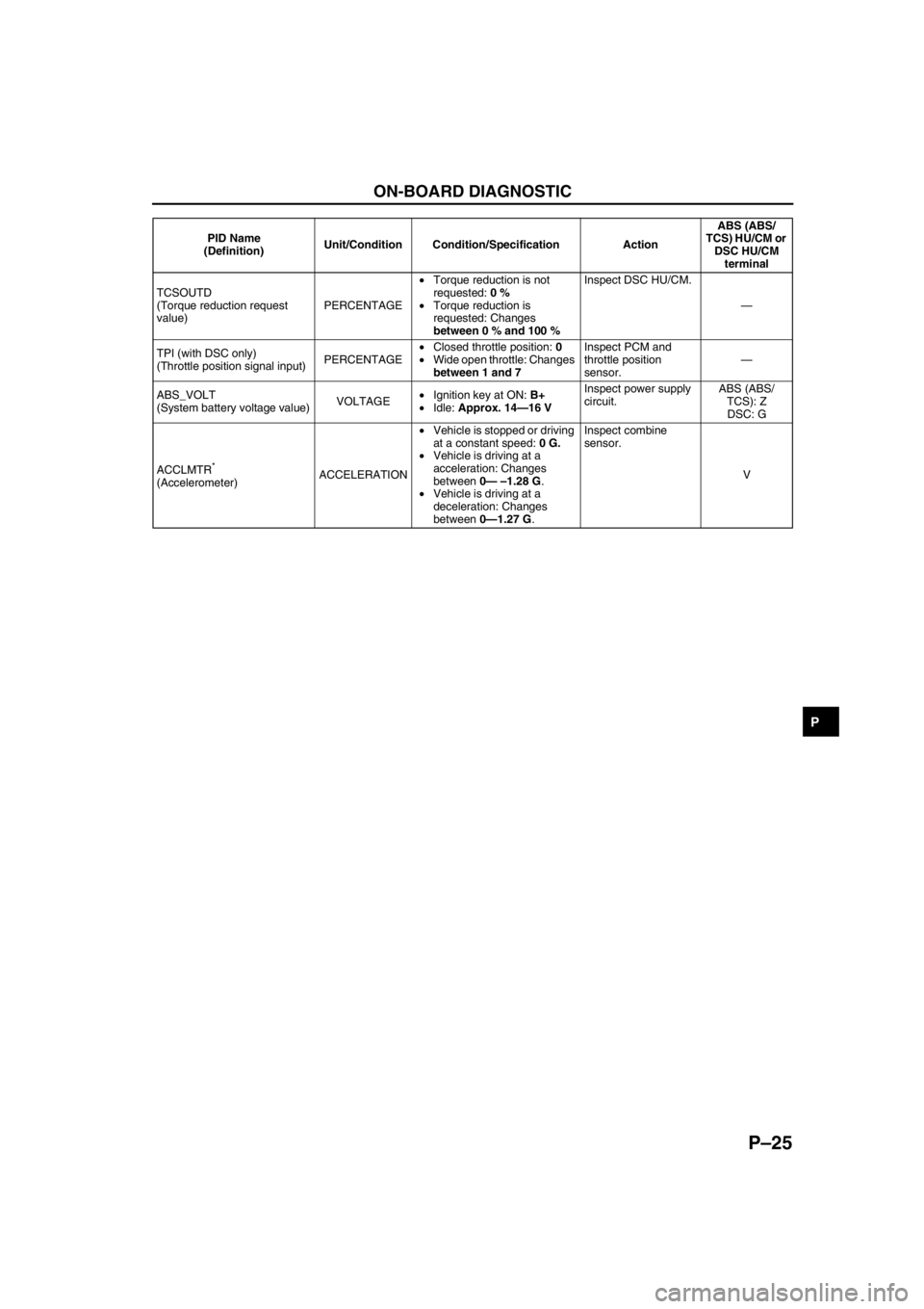
TCSOUTD
(Torque reduction request
value)PERCENTAGE•Torque reduction is not
requested: 0 %
•Torque reduction is
requested: Changes
between 0 % and 100 %Inspect DSC HU/CM.
—
TPI (with DSC only)
(Throttle position signal input)PERCENTAGE•Closed throttle position: 0
•Wide open throttle: Changes
between 1 and 7Inspect PCM and
throttle position
sensor.—
ABS_VOLT
(System battery voltage value)VOLTAGE•Ignition key at ON: B+
•Idle: Approx. 14—16 VInspect power supply
circuit.ABS (ABS/
TCS): Z
DSC: G
ACCLMTR
*
(Accelerometer)ACCELERATION•Vehicle is stopped or driving
at a constant speed: 0 G.
•Vehicle is driving at a
acceleration: Changes
between 0— –1.28 G.
•Vehicle is driving at a
deceleration: Changes
between 0—1.27 G.Inspect combine
sensor.
V PID Name
(Definition)Unit/Condition Condition/Specification ActionABS (ABS/
TCS) HU/CM or
DSC HU/CM
terminal
Page 759 of 909

P–26
ON-BOARD DIAGNOSTIC
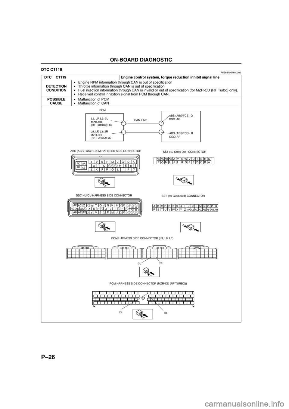
DTC C1119A6E697067650202
DTC C1119 Engine control system, torque reduction inhibit signal line
DETECTION
CONDITION•Engine RPM information through CAN is out of specification
•Throttle information through CAN is out of specification
•Fuel injection information through CAN is invalid or out of specification (for MZR-CD (RF Turbo) only).
•Received control inhibition signal from PCM through CAN.
POSSIBLE
CAUSE•Malfunction of PCM
•Malfunction of CAN
PCM
PCM HARNESS SIDE CONNECTOR (L3, L8, LF)
2U2R
CAN LINEABS (ABS/TCS): O
DSC: AG
ABS (ABS/TCS): R
DSC: AF
AQ
B
CDE
FG
HI
J DSC HU/CU HARNESS SIDE CONNECTOR
A
C E
H
K N Q
T
W Z AC AF
F I L O R U X
AA AD AG
G
J
M P S
V
Y AB
AE AHB
DKN
T
WZ
AC
AFLO
RU
XAA
ADAGMP
SV
YAB
AEAH
SST (49 G066 001) CONNECTOR
AD AC AB AAA Q
B R
C S
D T
E U
F V
G W
H X
I Y
J L M
O PZ ABS (ABS/TCS) HU/CM HARNESS SIDE CONNECTOR
ADAC
ABAA
A
B
C D
E
F G
H
I J
L M
O P
Q
R S
T
U V
W
X Y
Z
SST (49 G066 004) CONNECTOR
PCM HARNESS SIDE CONNECTOR (MZR-CD (RF TURBO))
13
39
L8, LF, L3: 2U
MZR-CD
(RF TURBO): 13
L8, LF, L3: 2R
MZR-CD
(RF TURBO): 39
Page 760 of 909

ON-BOARD DIAGNOSTIC
P–27
P
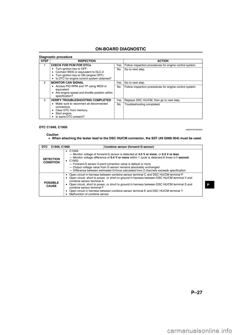
Diagnostic procedure
End Of Sie
DTC C1949, C1950A6E697067650203
Caution
•When attaching the tester lead to the DSC HU/CM connector, the SST (49 G066 004) must be used.
STEP INSPECTION ACTION
1CHECK FOR PCM FOR DTCs
•Turn ignition key to OFF.
•Connect WDS or equivalent to DLC-2
•Turn ignition key to ON (engine OFF).
•Is DTC for engine control system obtained?Yes Follow inspection procedures for engine control system.
No Go to next step.
2MONITOR CAN SIGNAL
•Access PID RPM and TP using WDS or
equivalent.
•Are engine speed and throttle position within
specification?Yes Go to next step.
No Follow inspection procedures for engine control system.
3VERIFY TROUBLESHOOTING COMPLETED
•Make sure to reconnect all disconnected
connectors.
•Clear DTC from memory.
•Start engine.
•Is same DTC present?Yes Replace DSC HU/CM, then go to next step.
No Troubleshooting completed.
DTC C1949, C1950 Combine sensor (forward G-sensor)
DETECTION
CONDITION•C1949:
—Monitor voltage of forward-G sensor is detected at 4.5 V or more, or 0.5 V or less.
—Monitor voltage difference of 0.4 V or more within 1 cycle is detected 8 times in 1 second.
•C1950:
—Forward-G sensor 0-point correction value is default or more
—Output voltage value from G sensor remains absolutely unchanged
—Difference between estimated G-force calculated from 2 channels exceeds specification
POSSIBLE
CAUSE•Open circuit in harness between combine sensor terminal C and DSC HU/CM terminal P
•Open circuit, short to power, or short to ground in harness between DSC HU/CM terminal V and
combine sensor terminal A
•Open circuit, short to power, or short to ground in harness between DSC HU/CM terminal S and
combine sensor terminal F
•Open circuit in harness between combine sensor terminal E and DSC HU/CM terminal Y
•Malfunction of combine sensor