MAZDA 6 2002 Workshop Manual Suplement
Manufacturer: MAZDA, Model Year: 2002, Model line: 6, Model: MAZDA 6 2002Pages: 909, PDF Size: 17.16 MB
Page 731 of 909

ENGINE SPEED SENSING POWER STEERING
N–17
N
POWER STEERING OIL PUMP (MZR-CD (RF TURBO)) DISASSEMBLY/ASSEMBLYA6E661432650202
Note
•The following procedure is for replacement of the O-ring and oil seal only. Replace the pump component if
other repairs are necessary.
1. Disassemble in the order indicated in the table.
2. Assemble in the reverse order of disassembly.
.
9
8
7
5
4
3
10
6
1
2
15
16
14
13
11
12
SST
R
ATFTF
22—26
{2.3—2.6, 17—19}
N·m {kgf·m, ft·lbf}
R
ATFTF
R
R
ATFTF
ATFTF
ATFTF
R
31.1—47.0
{3.18—4.79, 23.0—34.6}
31.1—47.0
{3.18—4.79, 23.0—34.6}
A6E66142007
1 Power steering oil pump component
(See N–18 Power Steering Oil Pump Component
Disassembly Note)
2Clip
(See N–18 Clip Disassembly Note)
(See N–19 Clip Assembly Note)
3 Reservoir tank4 O-ring
5Joint
6 Connector
7 O-ring
8 Control valve
9Spring
Page 732 of 909

N–18
ENGINE SPEED SENSING POWER STEERING
Power Steering Oil Pump Component Disassembly Note
1. Secure the power pressure oil pump using the SST.
Caution
•Use the SST to prevent damage to the
pump when securing it in a vise.
Clip Disassembly Note
1. Lift up the clip tab using a flathead screwdriver.
2. Remove the clip by pushing it with a flathead
screwdriver and a hammer as shown in the figure.
Vane Assembly Note
1. Place the vanes in the rotor with the rounded
edges contacting the cam.
10 Rear pump body
(See N–19 Rear Pump Body Assembly Note)
11 Gasket
12 Cam ring
(See N–19 Cam Ring Assembly Note)13 Rotor
14 Vane
(See N–18 Vane Assembly Note)
15 Side plate
16 Power steering oil pump
49 F032 301
A6E66142010
CLIP
R
A6E66142008
A6E6316W013
Page 733 of 909

ENGINE SPEED SENSING POWER STEERING
N–19
N
Cam Ring Assembly Note
1. Install the cam ring in the front pump body with
the mark facing upward.
Rear Pump Body Assembly Note
1. After installing the rear body, manually turn the shaft to verify that it rotates smoothly.
Clip Assembly Note
1. Push the clip slowly in the direction shown in the
figure.
2. Confirm that the clip tab is securely fastened.
End Of Sie
A6E6316W014
CLIP
R
A6E66142009
Page 734 of 909

P–1
P
PBRAKING SYSTEM
OUTLINE................................................................ P-2
OUTLINE OF CONSTRUCTION.......................... P-2
FEATURES .......................................................... P-2
SPECIFICATIONS ............................................... P-2
STRUCTURAL VIEW ........................................... P-3
ABS/TCS................................................................ P-4
OUTLINE.............................................................. P-4
DYNAMIC STABILITY CONTROL......................... P-6
OUTLINE.............................................................. P-6
COMBINE SENSOR
(FORWARD-G SENSOR) ................................. P-8
CONTROLLER AREA NETWORK (CAN) ........... P-8
ON-BOARD DIAGNOSTIC..................................... P-9
OUTLINE.............................................................. P-9
OUTLINE.............................................................. P-10
SUPPLEMENTAL SERVICE INFORMATION ... P-10
GENERAL PROCEDURES.................................. P-10
PRECAUTION (BRAKES).................................. P-10
CONVENTIONAL BRAKE SYSTEM.................... P-11
POWER BRAKE UNIT
REMOVAL/INSTALLATION ............................ P-11
VACUUM SWITCH INSPECTION
(MZR-CD (RF TURBO)) .................................. P-11
VACUUM SWITCH
REMOVAL/INSTALLATION
(MZR-CD (RF TURBO)) .................................. P-12
VACUUM PUMP INSPECTION
(MZR-CD (RF TURBO)) .................................. P-12
VACUUM PUMP REMOVAL/INSTALLATION
(MZR-CD (RF TURBO)) .................................. P-13
FRONT BRAKE (DISC) INSPECTION............... P-13
FRONT BRAKE (DISC)
REMOVAL/INSTALLATION ............................ P-14
DISC PAD (FRONT) REPLACEMENT .............. P-16
PARKING BRAKE SYSTEM................................ P-17
PARKING BRAKE (LEVER TYPE)
ADJUSTMENT ................................................ P-17
DYNAMIC STABILITY CONTROL....................... P-17
DSC HU/CM INSPECTION ................................ P-17
COMBINE SENSOR
(FORWARD-G SENSOR) INSPECTION ........ P-20
ON-BOARD DIAGNOSTIC................................... P-21
DSC ON-BOARD DIAGNOSIS .......................... P-21
DTC C1119 ........................................................ P-26
DTC C1949, C1950............................................ P-27
DTC U2511 ........................................................ P-29 FEATURES
SERVICE
Page 735 of 909

P–2
OUTLINE
OUTLINE OF CONSTRUCTIONA6E690201020201•The construction and operation of the braking system is the same as that of the current Mazda6 (GG) L8, LF,
L3 engine 2WD model, except for the following features. (See Mazda6 Training Manual 3359-1*-02C.)
End Of Sie
FEATURESA6E690201020202Modifications to match vehicle characteristics
•Due to the addition of the MZR-CD (RF Turbo) engine, the vacuum pump and vacuum switch have been
added.
•Due to the addition of the 4WD model, DSC HU/CM uses the forward-G signal from combine sensor to control
DSC.
End Of Sie
SPECIFICATIONSA6E690201020203
Bold frames: New specifications
End Of Sie
OUTLINE
ItemSpecification
New Mazda6 (GG, GW) Current Mazda6 (GG)
Brake pedalType Suspended
Pedal lever ratio 2.7
Max. stroke (mm {in}) 128.5 {5.06}
Master
cylinderType Tandem (with level sensor)
Cylinder diameter (mm {in}) 20.64 {0.813}
Front disc
brakeType Ventilated disc
Cylinder bore (mm {in}) 57.15 {2.250}
Pad dimensions (area × thickness) L8, LF (GCC specs.):
4,220 {6.75} × 10.0 {0.39}
LF (European (L.H.D. U.K.)
specs.), L3, MZR-CD (RF Turbo):
4,010 {6.42} × 12.0 {0.47}L8, LF (GCC specs.):
4,220 {6.75} × 10.0 {0.39}
LF (European (L.H.D. U.K.) specs.),
L3: 4,010 {6.42} × 12.0 {0.47} (mm
2 {in2} × mm {in})
Disc plate dimensions
(outer diameter × thickness)L8, LF (GCC specs.):
274 {10.8} × 24.0 {0.945}
LF (European (L.H.D. U.K.)
specs.), L3, MZR-CD (RF Turbo):
283 {11.1} × 25.0 {0.984}L8, LF (GCC specs.):
274 {10.8} × 24.0 {0.945}
LF (European (L.H.D. U.K.) specs.),
L3: 283 {11.1} × 25.0 {0.984} (mm {in} × mm {in})
Rear brake
(disc)Type Solid disc
Cylinder bore (mm {in}) 34.93 {1.375}
Pad dimensions (area × thickness)
2,810 {4.51} × 8.0 {0.31}
(mm
2 {in2} × mm {in})
Disc plate dimensions
(outer diameter × thickness)
280 {11.0} × 10.0 {0.39}
(mm {in})
Power brake
unitType Vacuum multiplier, single diaphragm
Diameter (mm {in}) 279 {10.9}
Braking force
control deviceTypeWith ABS: EBD (Electronic Brakeforce Distribution)
Without ABS: Dual proportioning valve
Parking brakeType Mechanical two-rear-wheel control
Operation system Center lever type
Brake fluid TypeEuropean (L.H.D. U.K.) specs.: SAE J1703, FMVSS116 DOT3 OR DOT4
GCC specs.: SAE J1703, FMVSS116 DOT3
Page 736 of 909

OUTLINE
P–3
P
STRUCTURAL VIEWA6E690201020204
.
End Of Sie
7
53
1
2
6
7
53
6
89
4
4
8
10
15
14
15
14
12
13
13
12
11
11
16
16
A6E6902W201
1L.H.D.
2 R.H.D.
3 Brake pedal
4 Master cylinder
5 Power brake unit
6 Front brake (disc)
7 Rear brake (disc)
8 Vacuum pump9 Without ABS
10 Dual proportioning valve
11 ABS (ABS/TCS) or DSC HU/CM
12 ABS wheel-speed sensor (front)
13 ABS sensor rotor (front)
14 ABS wheel-speed sensor (rear)
15 ABS sensor rotor (rear)
16 Combine sensor
Page 737 of 909

P–4
ABS/TCS
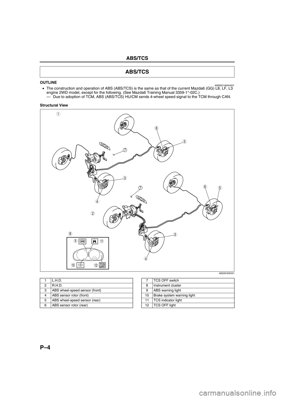
OUTLINEA6E692146444201•The construction and operation of ABS (ABS/TCS) is the same as that of the current Mazda6 (GG) L8, LF, L3
engine 2WD model, except for the following. (See Mazda6 Training Manual 3359-1*-02C.)
—Due to adoption of TCM, ABS (ABS/TCS) HU/CM sends 4-wheel speed signal to the TCM through CAN.
Structural View
.
ABS/TCS
5
3
1
2
6
7
5
3
6
8
4
4
7
9
10TCS
OFF
11
12
A6E6916W201
1 L.H.D.
2 R.H.D.
3 ABS wheel-speed sensor (front)
4 ABS sensor rotor (front)
5 ABS wheel-speed sensor (rear)
6 ABS sensor rotor (rear)7 TCS OFF switch
8 Instrument cluster
9 ABS warning light
10 Brake system warning light
11 TCS indicator light
12 TCS OFF light
Page 738 of 909

ABS/TCS
P–5
P
System Diagram
.
End Of Sie
9
9
8
7
5
43
12
6
18
17
15
16
14
13
11
12
RF
FL
RR
RL
PCMG
E
FI Z
U
D
A
B
C
Y
AC
X
V O
R ADAB AA
ABS/TCS HU/CM
pP
9
10
19
920
A6E6921W201
1 IG switch
2SUS 15 A fuse
3 ABS 60 A fuse
4 Meter
5 ABS warning light
6 Brake system warning light
7 TCS OFF light
8 TCS indicator light
9CAN driver
10 Brake light11 Cruise actuator
12 TCS OFF switch
13 DLC-2
14 CAN-H
15 CAN-L
16 ABS Wheel-speed sensor
17 Battery
18 Brake switch
19 Audio unit, Wiper and washer switch, Car-navigation
unit, Auto leveling control unit
20 TCM, 4WD CM
Page 739 of 909

P–6
DYNAMIC STABILITY CONTROL
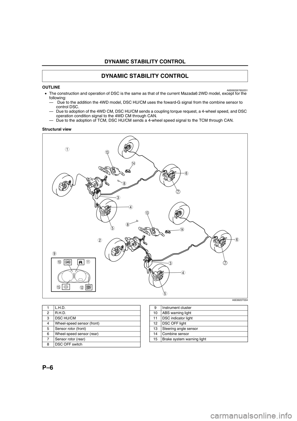
OUTLINEA6E692067650201•The construction and operation of DSC is the same as that of the current Mazada6 2WD model, except for the
following:
— Due to the addition the 4WD model, DSC HU/CM uses the foward-G signal from the combine sensor to
control DSC.
—Due to adoption of the 4WD CM, DSC HU/CM sends a coupling torque request, a 4-wheel speed, and DSC
operation condition signal to the 4WD CM through CAN.
—Due to the adoption of TCM, DSC HU/CM sends a 4-wheel speed signal to the TCM through CAN.
Structural view
.
DYNAMIC STABILITY CONTROL
7
5
4
3
1
2
14
13
6
13
12
5
4
3
7
6
1011
9
14
8
8
15
A6E6920T004
1 L.H.D.
2 R.H.D.
3 DSC HU/CM
4 Wheel-speed sensor (front)
5 Sensor rotor (front)
6 Wheel-speed sensor (rear)
7 Sensor rotor (rear)
8 DSC OFF switch9 Instrument cluster
10 ABS warning light
11 DSC indicator light
12 DSC OFF light
13 Steering angle sensor
14 Combine sensor
15 Brake system warning light
Page 740 of 909

DYNAMIC STABILITY CONTROL
P–7
P
Wiring Diagram
.
9
RF
FL
RR
RL
PCM
G
E
M
I
F
K
H
Q
NJ
P
S
T
V
O
Y
X
W
U
R
L
Z
AC
D
B
AG
AF
AE
AC
AA
AB
C
F
D
A
B
EDSC HU/CM
A
B
C
D
F
1
3
2
8
7
5
4
6
9
9
9
10
11
13
12
15
14
18
17
16
1920
2122
24
23
A6E6921W203
1 IG switch
2SUS 15A fuse
3 ABS 60 A fuse
4 Meter
5 ABS warning light
6 Brake system warning light
7 DSC OFF light
8 DSC indicator light
9CAN driver
10 Battery
11 Cruise actuator
12 DSC OFF switch13 DLC-2
14 CAN-H
15 CAN-L
16 Wheel-speed sensor
17 Combine sensor
18 Steering angle sensor
19 Brake switch
20 Brake light
21 Back-up light switch (MTX only)
22 Back-up light (MTX only)
23 Audio unit, Wiper and washer switch, Car-navigation
unit, Auto leveling control unit
24 TCM, 4WD CM