temperature MAZDA 626 1987 Owners Manual
[x] Cancel search | Manufacturer: MAZDA, Model Year: 1987, Model line: 626, Model: MAZDA 626 1987Pages: 1865, PDF Size: 94.35 MB
Page 936 of 1865

7B ELECTRICAL SYSTEM COMPONENTS
Terminal Connected to Voltage Condition
1J — — —
1K — — —
1L (Input) Idle switch Below 1.5V At idle 1L (Input) Idle switch Approx. 12V Other speeds
1M — — —
1N (Input) Brake light switch Approx. 12V Brake pedal depressed 1N (Input) Brake light switch Below 1.5V Brake pedal released
10 (Input) Throttle sensor
Approx. 5V Ignition switch ON 10 (Input) Throttle sensor Below 1,5V Ignition switch OFF
1P (Input)
Throttle sensor
Approx. 0.5—4.3V Throttle valve fully closed to fully open
1Q (Input) Vehicle speed sensor
Approx. 4.5V During driving
1Q (Input) Vehicle speed sensor Approx. 4.5V or below 1.5V Vehicle stopped
1R (Ground) Throttle sensor Below 1,5V —
1S (Input) Pulse generator Approx. 12V Engine running 1S (Input) Pulse generator Below 1,5V Engine stopped
1S (Ground) Pluse generator Below 1.5V —
2A (Battery power) Battery Approx. 12V Ignition switch ON 2A (Battery power) Battery Below 1,5V Ignition switch OFF
2B (Ground) Body ground Below 1,5V —
2C (Memory power) Battery Approx. 12V —
2D (Ground) Body ground Below 1,5V —
2E (Output) 1-2 shift solenoid valve Approx. 12V
Refer to page 7B—26 of solenoid valve
operation table
2E (Output) 1-2 shift solenoid valve Below 1.5V Refer to page 7B—26 of solenoid valve
operation table
2F (Output) 2-3 shift solenoid valve Approx. 12V
Refer to page 7B—26 of solenoid valve
operation table
2F (Output) 2-3 shift solenoid valve Below 1,5V
Refer to page 7B—26 of solenoid valve
operation table
2G — — —
2H (Output) 3-4 shift solenoid valve Approx. 12V Refer to page 7B—26 of solenoid valve operation table 2H (Output) 3-4 shift solenoid valve Below 1.5V
Refer to page 7B—26 of solenoid valve operation table
21 — — —
2J (Output) Lock-up solenoid valve Approx. 12V Lock-up 2J (Output) Lock-up solenoid valve Below 1,5V Other
2K (Output) Hold indicator Below 1,5V Hold mode 2K (Output) Hold indicator Approx. 12V Other modes
2L (Output) Mode indicator Approx. 12V Hold mode 2L (Output) Mode indicator Below 1,5V Power or economy mode
2M (Output) EC-AT Tester
(malfunction code)
Approx. 12V Normal
2M (Output) EC-AT Tester
(malfunction code) Below 1,5V If malfunction present 2M (Output) EC-AT Tester
(malfunction code) Code signal Self-diagnosis check connector grounded
2N — — —
20 (Input) Fluid temperature switch Below 1,5V Above 150°C (302°F) 20 (Input) Fluid temperature switch Approx. 10—12V Below 143°C (289°F)
2P (Input) EC-AT check connect Approx. 12V —
76G07B-084
7B-70
Page 937 of 1865

ON-VEHICLE MAINTENANCE 7B
ON-VEHICLE MAINTENANCE
AUTOMATIC TRANSAXLE FLUID (ATF)
Inspection for Fluid Leaks
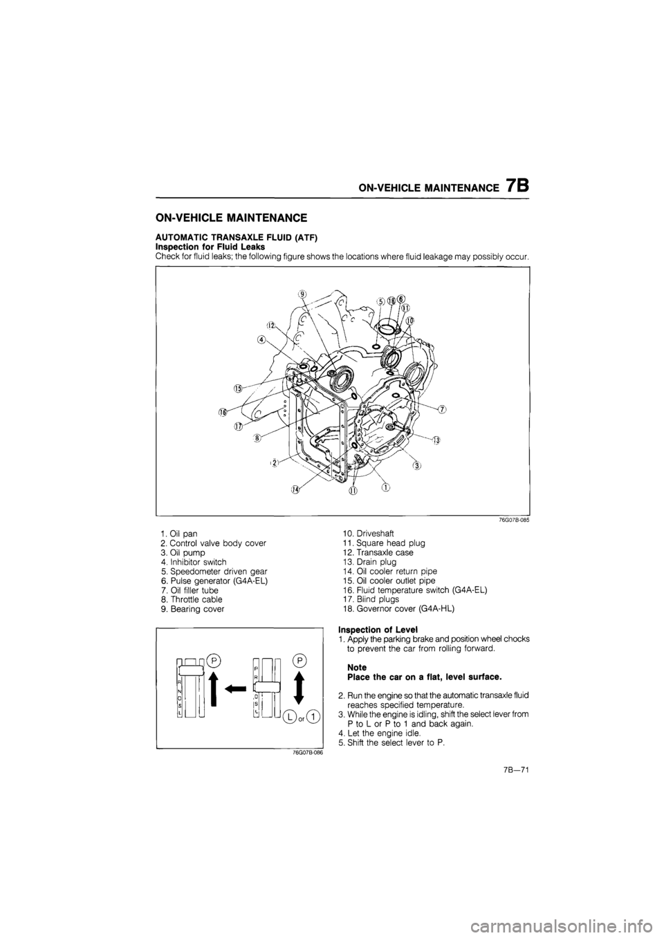
Check for fluid leaks; the following figure shows the locations where fluid leakage may possibly occur.
1. Oil pan
2. Control valve body cover
3. Oil pump
4. Inhibitor switch
5. Speedometer driven gear
6. Pulse generator (G4A-EL)
7. Oil filler tube
8. Throttle cable
9. Bearing cover
76G07B-085
10. Driveshaft
11. Square head plug
12. Transaxle case
13. Drain plug
14. Oil cooler return pipe
15. Oil cooler outlet pipe
16. Fluid temperature switch (G4A-EL)
17. Blind plugs
18. Governor cover (G4A-HL)
Inspection of Level
1. Apply the parking brake and position wheel chocks
to prevent the car from rolling forward.
Note
Place the car on a flat, level surface.
2. Run the engine so that the automatic transaxle fluid
reaches specified temperature.
3. While the engine is idling, shift the select lever from
P to L or P to 1 and back again.
4. Let the engine idle.
5. Shift the select lever to P.
76G07B-086
7B—71
Page 938 of 1865
![MAZDA 626 1987 Owners Manual
7B ON-VEHICLE MAINTENANCE
86U07B-064
86U07B-065
t «
•A
0 0
0 »
LX] O 9
m
(2)
(1)
Button need not
be depressed
Button must be pressed
76F07B-022
6. Ensure that the ATF level is be MAZDA 626 1987 Owners Manual
7B ON-VEHICLE MAINTENANCE
86U07B-064
86U07B-065
t «
•A
0 0
0 »
LX] O 9
m
(2)
(1)
Button need not
be depressed
Button must be pressed
76F07B-022
6. Ensure that the ATF level is be](/img/28/57059/w960_57059-937.png)
7B ON-VEHICLE MAINTENANCE
86U07B-064
86U07B-065
t «
•A
0 0
0 »
LX] O 9
m
(2)
(1)
Button need not
be depressed
Button must be pressed
76F07B-022
6. Ensure that the ATF level is between the F and L
marks. Add ATF to specification, if necessary.
Low temperature scale:
20°C (68°F)
High temperature scale:
65°C (149°F)
ATF type:
Dexron II or M HI
Inspection of Condition
1. Check the ATF for discoloration.
2. Check the ATF for any unusual smell.
Note
Determine whether or not the automatic trans-
mission should be disassembled by observ-
ing the condition of fluid carefully.
If the fluid is muddy and varnished, it indicates
burned drive plates.
SELECTOR LEVER
Inspection
1. Check that the selector lever can only be shifted
as shown in the figure.
2. Make sure there is a click at each range when shift-
ed from P <-> L or P <-» 1 range.
3. Check that the position of the selector lever and
the indicator are exact.
4. Check that the button returns smoothly when used
to shift the selector.
Adjustment
1. Loosen locknuts A, B, and lockbolt C.
2. Shift the selector lever to P range.
3. Shift the transaxle to P range by moving the man-
ual shaft of the transaxle.
4. While holding the selector lever forward in P range,
tighten lockbolt C to the specified torque.
Tightening torque:
8—11 N-m (80—110 cm-kg, 67—95 in-lb)
76F07B-023
7B—72
Page 941 of 1865

ON-VEHICLE MAINTENANCE 7B
'mfm^i! kfOl iff t—
76G07B-093
76G07B-094
Main fuse block (G4A-EL)
Install the main fuse block.
Tightening torque:
8—11 Nm (80—110 cm-kg, 69—95 in-lb)
Battery carrier
Install the battery carrier.
Tightening torque:
31—40 Nm (3.2—4.1 m-kg, 23—30 ft-lb)
ATF level
After installation, add ATF, and with the engine idling,
check the fluid level and for leaks. (Refer to page
7 B—71)
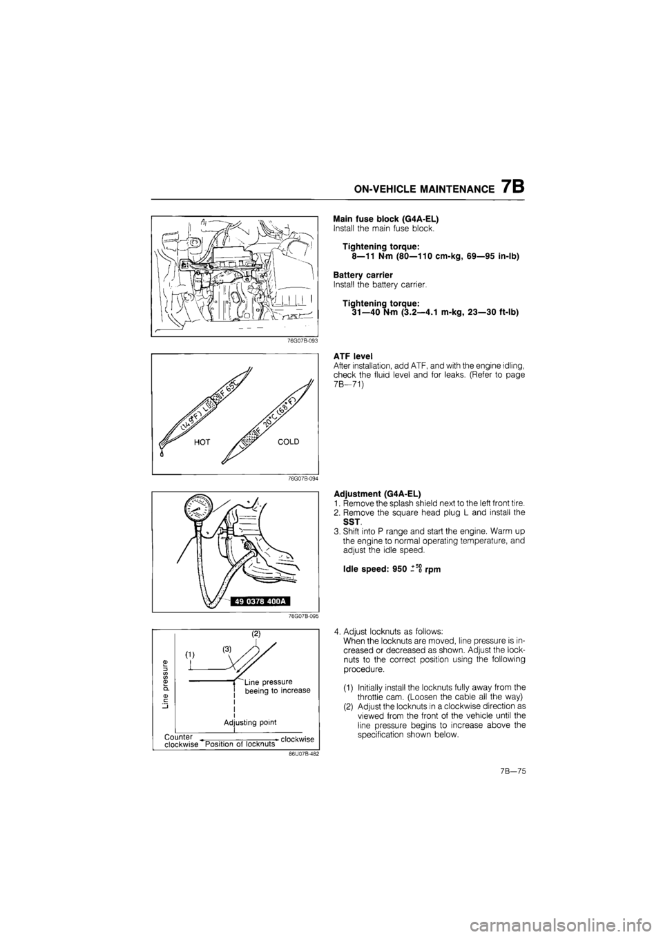
Adjustment (G4A-EL)
1. Remove the splash shield next to the left front tire.
2. Remove the square head plug L and install the
SST
3. Shift into P range and start the engine. Warm up
the engine to normal operating temperature, and
adjust the idle speed.
Idle speed: 950 ±5o rpm
76G07B-095
3 CO CO 03
(1)
L
Line pressure
beeing to increase
I
Adjusting point
•
clockwise Counter
clockwise Position of locknuts
86U07B-482
4. Adjust locknuts as follows:
When the locknuts are moved, line pressure is in-
creased or decreased as shown. Adjust the lock-
nuts to the correct position using the following
procedure.
(1) Initially install the locknuts fully away from the
throttle cam. (Loosen the cable all the way)
(2) Adjust the locknuts in a clockwise direction as
viewed from the front of the vehicle until the
line pressure begins to increase above the
specification shown below.
7B—75
Page 942 of 1865

7B ON-VEHICLE MAINTENANCE
Line pressure decreases
Line pressure increases
86U07B-483
Protector
-7 / Throttle cable
86U07B-080
(3) Adjust the locknuts in a counterclockwise direc-
tion until the line pressure decreases to the
specification. Tighten the locknuts.
Specified pressure: 432—450 kPa
(4.4—4.6 kg/cm2, 63—66 psi)
Note
Transmission in P range
5. Turn off the engine.
6. Reinstall the square head plug.
Tightening torque:
5—10 N m (50—100 cm-kg, 43—87 in-lb)
7. Fully open the throttle valve; then crimp the pin with
the protector installed as shown.
8. Remove the protector.
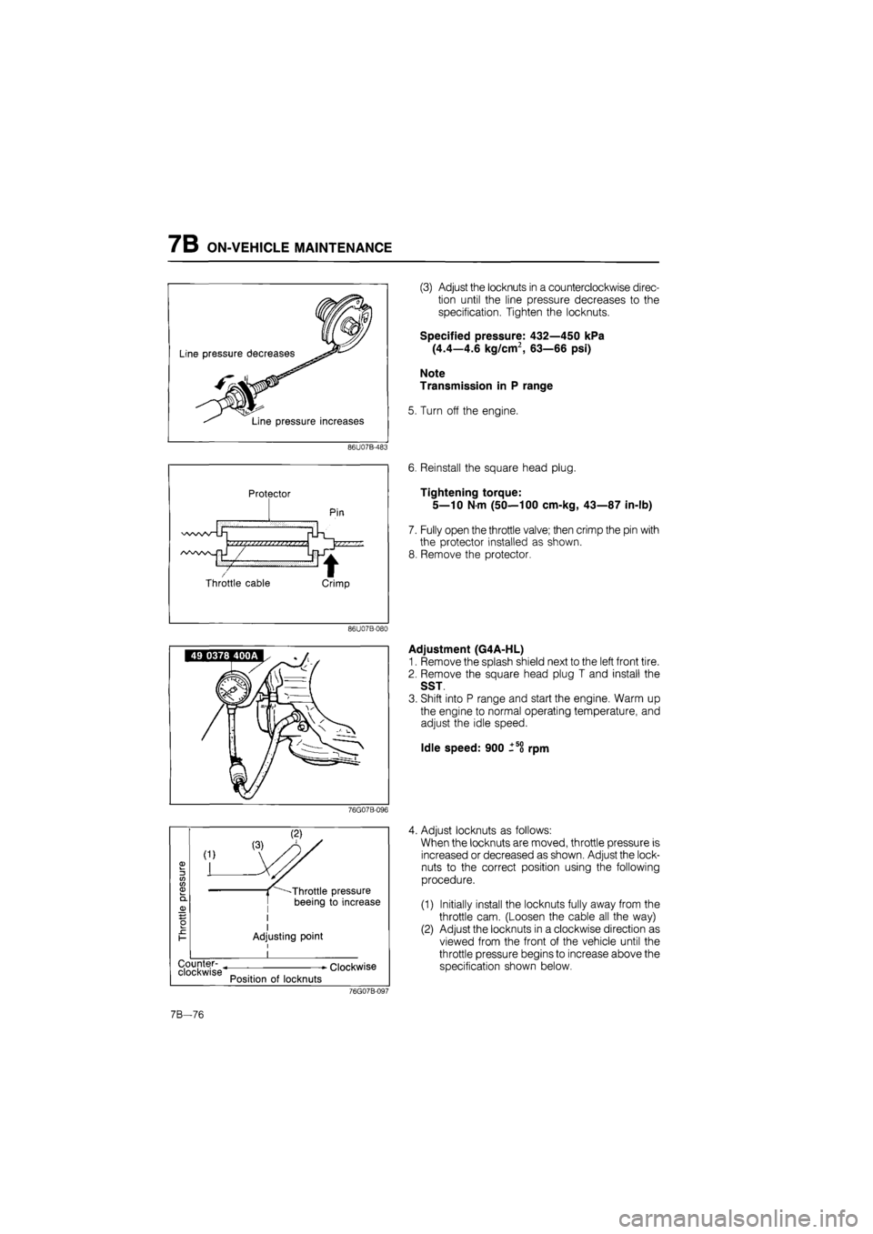
Adjustment (G4A-HL)
1. Remove the splash shield next to the left front tire.
2. Remove the square head plug T and install the
SST
3. Shift into P range and start the engine. Warm up
the engine to normal operating temperature, and
adjust the idle speed.
Idle speed: 900 -5o rpm
76G07B-096
3 tn tn
L
Counter- ^ clockwise
Throttle pressure
beeing to increase
I Adjusting point
Position of locknuts
Clockwise
4. Adjust locknuts as follows:
When the locknuts are moved, throttle pressure is
increased or decreased as shown. Adjust the lock-
nuts to the correct position using the following
procedure.
(1) Initially install the locknuts fully away from the
throttle cam. (Loosen the cable all the way)
(2) Adjust the locknuts in a clockwise direction as
viewed from the front of the vehicle until the
throttle pressure begins to increase above the
specification shown below.
76G07B-097
7B—76
Page 950 of 1865

7B REMOVAL
76G07B-107
G4A-EL
76G07B-108
76G07B-109
1. Remove the battery and battery carrier.
2. Disconnect the main fuse block.
3. Disconnect the distributor lead.
4. Disconnect the air flow meter connector and re-
move the air cleaner assembly. (G4A-EL)
5. Remove the air cleaner hose. (G4A-EL)
6. Remove the fresh air duct. (G4A-HL)
7. Disconnect the speedometer cable.
8. Disconnect the connectors.
(1) Inhibitor switch
(2) Solenoid valve
(3) Pulse generator (G4A-EL)
(4) Fluid temperature switch (G4A-EL)
9. Disconnect the grounds from the transaxle case.
10. Disconnect the selector cable.
11. Disconnect the throttle cable.
76G07B-110
7B—84
Page 954 of 1865

7B DISASSEMBLY
DISASSEMBLY
DISASSEMBLY-STEP 1
Components
1. Torque converter
2. Oil pump shaft
3. Oil level gauge and oil filler tube
4. Pulse generator, fluid temperature switch,
and inhibitor switch
5. Solenoid connector
6. Wire harnesses
7. Harness clip
86U07B-116
8. Oil pipes, oil hoses, and switch box
9. Oil pan and gasket
10. Oil strainer and O-ring
11. Control valve body cover and gasket
12. Throttle cable
13. Solenoid connector (Valve body side)
14. Control valve body
15. Oil pump and gasket
7B-88
Page 957 of 1865

DISASSEMBLY 7B
6 G4A-EL
Remove the pulse generator, fluid temperature
switch, and inhibitor switch.
G4A-HL
Remove the inhibitor switch.
76GQ7B-123
7. Disconnect the solenoid connector.
8. Remove the harnesses.
76G07B-124
9. G4A-EL
Remove the harness clip, then remove the oil
pipes, oil hoses and switch box as an assembly.
Note
Remove the ball from the case.
76G07B-125
G4A-HL
Remove the oil pipe.
Note Remove the ball from the case.
76G07B-126
7B—91
Page 1079 of 1865

ASSEMBLY 7B
12. Install the pulse generator and fluid temperature
switch.
Tightening torque:
Pulse generator
8—11 N-m (80—110 cm-kg, 69—95 in-lb)
Fluid temperature switch
29—39 N-m (3.0—4.0 m-kg, 22—29 in-lb)
76G07B-190
76G07B-191
13. Install the inhibitor switch.
(1) Turn the manual shaft to the "N" position.
(2) Install the inhibitor switch and loosely tighten
the bolts.
(3) Remove the screw and move the inhibitor
switch so that the alignment hole is aligned with
the screw hole.
(4) Insert a 2.0 mm (0.079 in) diameter pin
through the holes.
(5) Install the screw; then tighten the bolts to the
specified torque.
Tightening torque:
8—11 N-m (80—110 cm-kg, 69—95 in-lb)
14. Install the harness with the remaining clip.
Tightening torque:
8—11 N-m (80—110 cm-kg, 69—95 in-lb)
15. Remove the transaxle from the SST.
76G07B-192
16. Install the oil level gauge and tube along with a new
O-ring to the transaxle case.
Tightening torque:
7—10 N-m (70—100 cm-kg, 61—87 in-lb)
76G07B-193
7B-213
Page 1086 of 1865

7B INSTALLATION
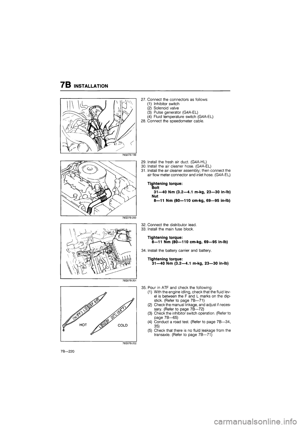
27. Connect the connectors as follows:
(1) Inhibitor switch
(2) Solenoid valve
(3) Pulse generator (G4A-EL)
(4) Fluid temperature switch (G4A-EL)
28. Connect the speedometer cable.
76G07B-199
76G07B-200
76G07B-201
29. Install the fresh air duct. (G4A-HL)
30. Install the air cleaner hose. (G4A-EL)
31. Install the air cleaner assembly; then connect the
air flow meter connector and inlet hose. (G4A-EL)
Tightening torque:
Bolt
31—40 N-m (3.2—4.1 m-kg, 23—30 in-lb)
Nut
8—11 N-m (80—110 cm-kg, 69—95 in-lb)
32. Connect the distributor lead.
33. Install the main fuse block.
Tightening torque:
8—11 N-m (80—110 cm-kg, 69—95 in-lb)
34. Install the battery carrier and battery.
Tightening torque:
31—40 N-m (3.2—4.1 m-kg, 23—30 in-lb)
35. Pour in ATF and check the following:
(1) With the engine idling, check that the fluid lev-
el is between the F and L marks on the dip-
stick. (Refer to page 7B—71)
(2) Check the manual linkage, and adjust if neces-
sary. (Refer to page 7B—72)
(3) Check the inhibitor switch operation. (Refer to
page 7B—65)
(4) Conduct a road test. (Refer to page 7B—34,
35)
(5) Check that there is no fluid leakage from the
transaxle. (Refer to page 7B—71)
76G07B-202
7B—220