engine MAZDA 626 1987 Workshop Manual
[x] Cancel search | Manufacturer: MAZDA, Model Year: 1987, Model line: 626, Model: MAZDA 626 1987Pages: 1865, PDF Size: 94.35 MB
Page 218 of 1865
1C TUNE-UP PROCEDURE
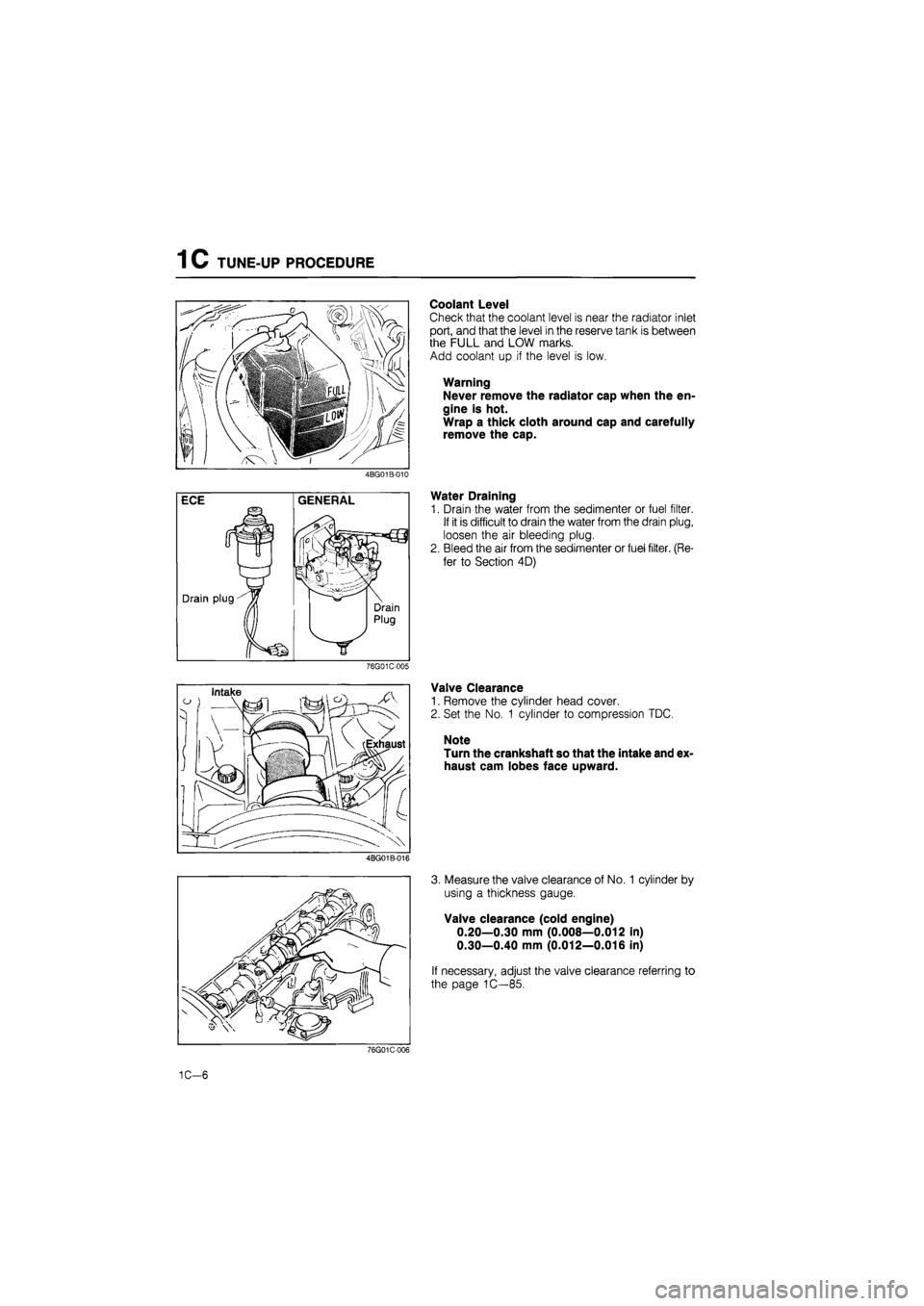
Coolant Level
Check that the coolant level is near the radiator inlet
port, and that the level in the reserve tank is between
the FULL and LOW marks.
Add coolant up if the level is low.
Warning
Never remove the radiator cap when the en-
gine is hot.
Wrap a thick cloth around cap and carefully
remove the cap.
4BG01B-010
Water Draining
1. Drain the water from the sedimenter or fuel filter.
If it is difficult to drain the water from the drain plug,
loosen the air bleeding plug.
2. Bleed the air from the sedimenter or fuel filter. (Re-
fer to Section 4D)
76G01C-005
Valve Clearance
1. Remove the cylinder head cover.
2. Set the No. 1 cylinder to compression TDC.
Note
Turn the crankshaft so that the intake and ex-
haust cam lobes face upward.
4BG01B-016
3. Measure the valve clearance of No. 1 cylinder by
using a thickness gauge.
Valve clearance (cold engine)
0.20—0.30 mm (0.008—0.012 in)
0.30—0.40 mm (0.012—0.016 in)
If necessary, adjust the valve clearance referring to
the page 1C—85.
76G01C-006
1C-6
Page 221 of 1865
TUNE-UP PROCEDURE 1C
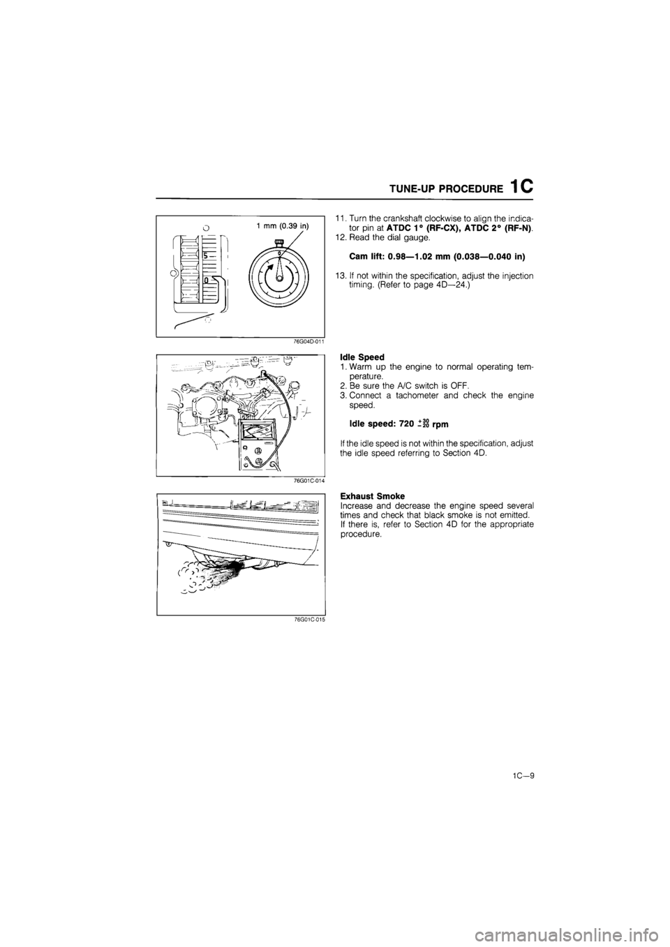
11. Turn the crankshaft clockwise to align the indica-
tor pin at ATDC 1° (RF-CX), ATDC 2° (RF-N)
12. Read the dial gauge.
Cam lift: 0.98—1.02 mm (0.038—0.040 in)
13. If not within the specification, adjust the injection
timing. (Refer to page 4D—24.)
76G04D-011
Idle Speed
1. Warm up the engine to normal operating tem-
perature.
2. Be sure the A/C switch is OFF.
3. Connect a tachometer and check the engine
speed.
Idle speed: 720 ±20 rpm
If the idle speed is not within the specification, adjust
the idle speed referring to Section 4D.
76G01C-014
Exhaust Smoke
Increase and decrease the engine speed several
times and check that black smoke is not emitted.
If there is, refer to Section 4D for the appropriate
procedure.
76G01C-015
1C—9
Page 222 of 1865
1C ON-VEHICLE INSPECTION
ON-VEHICLE INSPECTION
If the engine exhibits low power, poor fuel economy,
or poor idle, check the following:
1. Compression
2. Fuel system (Refer to Section 4D)
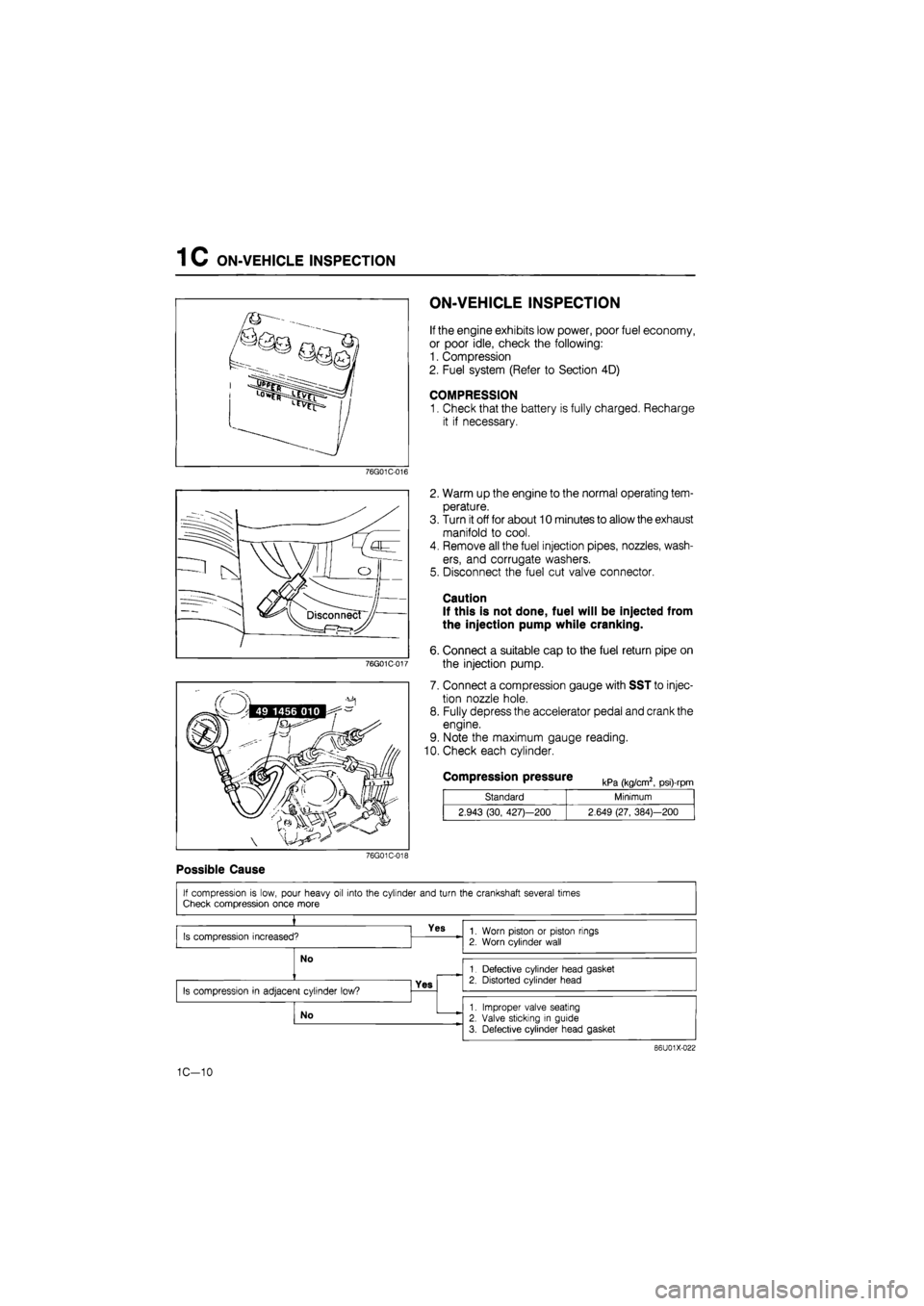
COMPRESSION
1. Check that the battery is fully charged, Recharge
it if necessary.
76G01C-016
76G01C-017
2. Warm up the engine to the normal operating tem-
perature.
3. Turn it off for about 10 minutes to allow the exhaust
manifold to cool.
4. Remove all the fuel injection pipes, nozzles, wash-
ers, and corrugate washers.
5. Disconnect the fuel cut valve connector.
Caution
If this is not done, fuel will be injected from
the injection pump while cranking.
6. Connect a suitable cap to the fuel return pipe on
the injection pump.
7. Connect a compression gauge with SST to injec-
tion nozzle hole.
8. Fully depress the accelerator pedal and crank the
engine.
9. Note the maximum gauge reading.
10. Check each cylinder.
Compression pressure kPa (kg/cm2, psi)-rpm
Standard Minimum
2.943 (30, 427)—200 2.649 (27, 384)—200
76G01C-018
Possible Cause
86U01X-022
1C-10
Page 223 of 1865

ON-VEHICLE MAINTENANCE (TIMING BELT) 1 C
ON-VEHICLE MAINTENANCE
TIMING BELT
Removal
1. Disconnect the nagative battery cable.
2. Remove in the sequence shown in the figure referring to the removal note for specially marked parts.
76G01C-019
1. Engine side cover
2. A/C and alternator drive belt
3. Crankshaft pulley
4. Left and right timing belt cover
5. Alternator idle pulley
6. Idler pulley
7. No.3 engine mount
8. Timing belt
9. Timing belt tensioner and spring
Note
Loosen the No.3 engine mount nuts and lower the engine to remove the crankshaft pulley.
1C-11
Page 224 of 1865

1 C ON-VEHICLE MAINTENANCE (TIMING BELT)
76G01C-020
76G01C-238
Kww
76G01C-021
Removal note
Timing belt
1. Aligh the timing marks of each pulleys.
2. Affix the injection pump pulley to the bracket us-
ing two bolts (35—40 mm, 1.4—1.6 in).
Caution
a) Do not turn in the reverse direction of en-
gine revolution.
b) After removing the timing belt, do not ro-
tate the crankshaft pulley or camshaft
pulley.
3. Make the forward direction arrow on the timing belt.
Note
Direction arrow is to reassemble the timing
belt in the same direction.
4. Loosen the timing belt tensioner bolt.
5. Shift the tensioner outwards as far as possible, and
temporarily tighten it.
6. Suspend the engine with chain block on the front
engine hanger.
7. Remove the No.3 engine mount.
8. Remove the timing belt.
Caution
Do not allow any oil or grease on the timing
belt.
Inspection and Repair
Inspect the following parts. (Refer to page 1C—60,
61).
1. Timing belt
2. Timing belt tensioner and spring
3. Timing belt idler pulley
4. Timing belt pulley
76G01C-022
1C—12
Page 227 of 1865
ON-VEHICLE MAINTENANCE (TIMING BELT) 1 C
76G01C-027
76G01C-028
76G01C-029
Checking
point
Idler pulley
Crankshaft pulley zQi A/C
Checking point compressor
76G01C-030
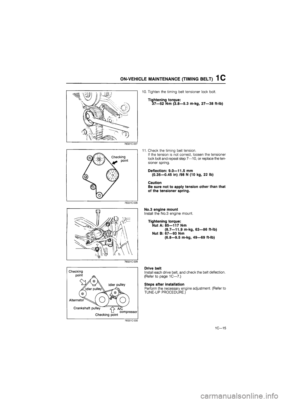
10. Tighten the timing belt tensioner lock bolt.
Tightening torque:
37—52
N
m (3.8—5.3 m-kg, 27—38 ft-lb)
11. Check the timing belt tension.
If the tension is not correct, loosen the tensioner
lock bolt and repeat step 7—10, or replace the ten-
sioner spring.
Deflection: 9.0—11.5 mm
(0.35—0.45 in) /98 N (10 kg, 22 lb)
Caution
Be sure not to apply tension other than that
of the tensioner spring.
No.3 engine mount
Install the No.3 engine mount.
Tightening torque:
Nut A: 85—117 N-m
(8.7—11.9 m-kg, 63—86 ft-lb)
Nut B: 67—93 N-m
(6.8—9.5 m-kg, 49—69 ft-lb)
Drive belt
Install each drive belt, and check the belt deflection.
(Refer to page 1C—7.)
Steps after installation
Perform the necessary engine adjustment. (Refer to
TUNE-UP PROCEDURE,)
1C-15
Page 228 of 1865

1 C ON-VEHICLE MAINTENANCE (CYLINDER HEAD)
CYLINDER HEAD
Removal
1. Disconnect the negative battery cable.
2. Drain the engine coolant.
3. Remove in the sequence shown in the figure referring to the removal note for specially marked parts.
76G01C-031
1. Accelerator cable
2. Air cleaner
3. Brake vacuum pipe
4. Intercooler pipe and hose*
5. Drive belt cover
6. Vacuum pump drive belt
7. Fuel hose
8. Water temperature switch
connector
9. Glow plug connector
10. Water thermo switch con-
nector
11. Heat gauge unit connector
12. Boost air temperature sen-
sor connector*
13. Injection pipes
14. Upper radiator hose
15. Water hose
(thermostat—FIR)
16. Oil level gauge and stay
bolt
17. Oil pipe bolt
18. Timing belt (Refer to page
1C—11)
19. Cylinder head cover
20. Camshaft pulley
21. Rear camshaft pulley
76G01C-032
22. Injection pump pulley
23. Seal plate
24. Water hose and pipe
25. Comprex supercharger
drive belt*
26. Heat insulator*
27. Exhaust manifold stay
28. Front exhaust pipe
29. Cylinder head bolt
30. Cylinder head
31. Cylinder head gasket
32. Comprex supercharger*
33. Exhaust manifold
34. Intake manifold
Note
* marked parts are equipped only for the RF-CX.
1C-16
Page 232 of 1865

ON-VEHICLE MAINTENANCE (CYLINDER HEAD) 1 C
76G01C-037
Apply engine oil
/
Cylinder head bolt
below head length
76G01C-038
(8) (4; D (5)
® ®
76G01C-039
3m-kg
(21.7ft-lb
Installation
Cylinder head
1. Throughly remove all dirt and grease from the top
of the cylinder block with a rag.
2. Place the new cylinder head gasket in position.
3. Remove any dirt and grease from the bottom sur-
face of the cylinder head.
4. Place the cylinder head in position.
5. Measure the length of the cylinder head bolt be-
low the head. If the length exceeds the maximum,
replace the bolt.
Length: 113.2—113.8 mm (4.457—4.480 in)
Maximum: 114.5 mm (4.508 in)
6. Apply engine oil to the threads and the seat face
of the cylinder head bolts.
7. Tighten the cylinder head bolts.
(1) Tighten the bolts to the specified torque, in the
order shown in the figure.
Tightening torque:
29 N-m (3.0 m-kg, 22 ft-lb)
(2) Make paint marks on the bolt heads, as shown
in the figure.
(3) With the paint marks as a reference point, turn
the cylinder head bolts another 90°
(90°—105°) in the tightening direction. Tight-
en them in the order.
(4) Then tighten them once again 90°
(90°—105°) in the tightening order.
Caution
Be absolutely sure that the bolts are tightened
in the proper order.
76G01C-044
1C—20
Page 235 of 1865
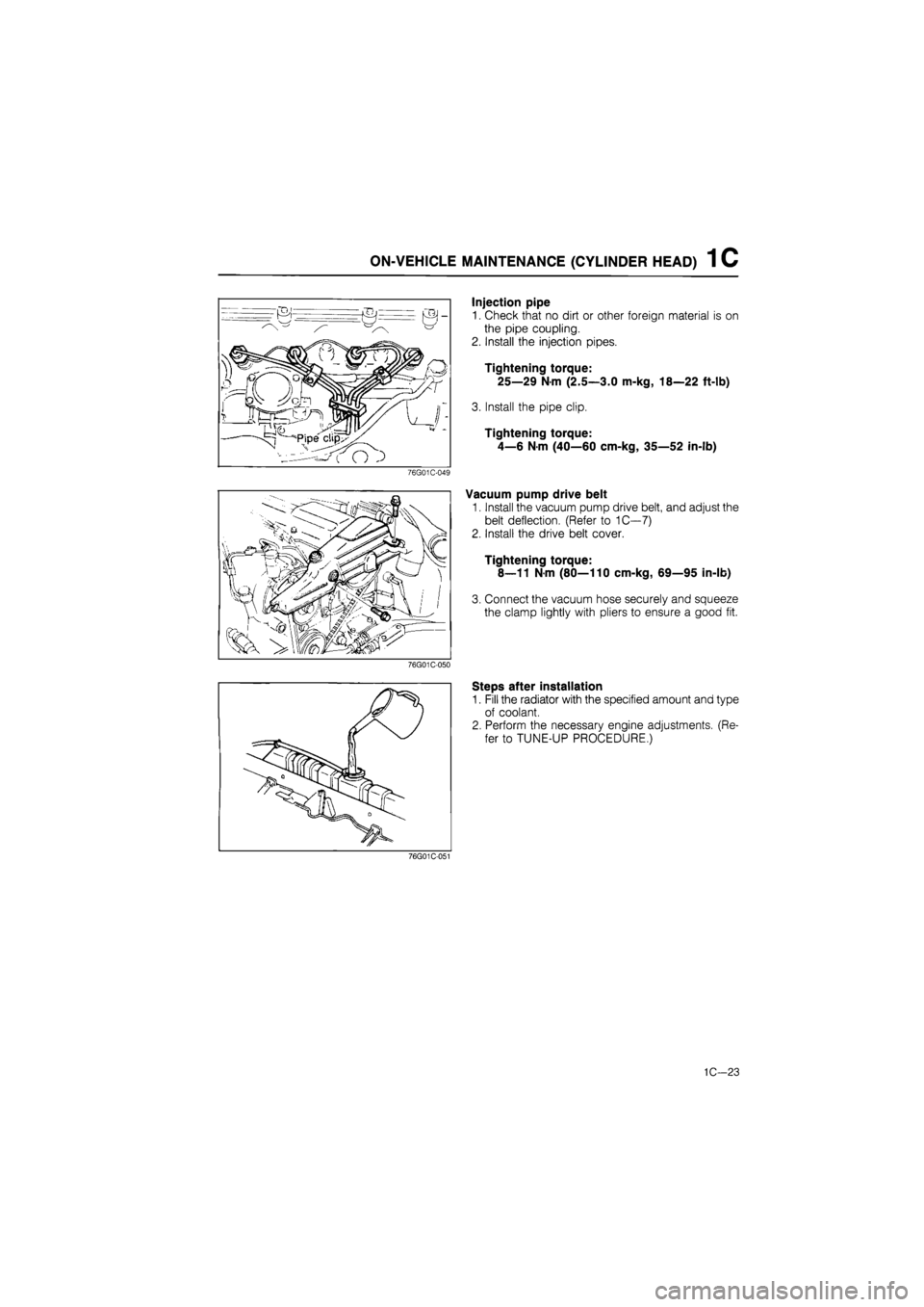
ON-VEHICLE MAINTENANCE (CYLINDER HEAD) 1 C
76G01C-049
Injection pipe
1. Check that no dirt or other foreign material is on
the pipe coupling.
2. Install the injection pipes.
Tightening torque:
25—29 Nm (2.5—3.0 m-kg, 18—22 ft-lb)
3. Install the pipe clip.
Tightening torque:
4—6 N-m (40—60 cm-kg, 35—52 in-lb)
Vacuum pump drive belt
1. Install the vacuum pump drive belt, and adjust the
belt deflection. (Refer to 1C—7)
2. Install the drive belt cover.
Tightening torque:
8—11 Nm (80—110 cm-kg, 69—95 in-lb)
3. Connect the vacuum hose securely and squeeze
the clamp lightly with pliers to ensure a good fit.
76G01C-050
Steps after installation
1. Fill the radiator with the specified amount and type
of coolant.
2. Perform the necessary engine adjustments. (Re-
fer to TUNE-UP PROCEDURE.)
76G01C-051
1C—23
Page 239 of 1865

ON-VEHICLE MAINTENANCE (VALVE SEAL) 1 C
Installation
Install in the reverse order of removal referring to the installation note.
Torque Specifications
20—26 N-m (2.0—2.7 m-kg, 14—20 ft-lb)
N-m (5.6—6.6 m-kg, ft-lb)
55—65 N m (5.6—6.6 m-kg, 41—48 ft-lb)
76G01C-243
Installation note
Valve seal
1. Apply engine oil to the inside of the new valve seal.
2. Push it on gently with the SST.
86U01X-049
1C—27