ignition MAZDA 626 1987 User Guide
[x] Cancel search | Manufacturer: MAZDA, Model Year: 1987, Model line: 626, Model: MAZDA 626 1987Pages: 1865, PDF Size: 94.35 MB
Page 42 of 1865

1A TUNE-UP PROCEDURE
No.1 IN No.2 IN
No.1 EX No.3 EX
76G01A-015
Adjust bolt
^N^^^^^Lock nut
SsKs&b ' Valve
Camshaft >Nw clearance
76G01A-016
76G01A-017
Valve Clearance (8-valve)
1. Warm up the engine to the normal operating tem-
perature.
2. With the piston of the No.1 cylinder at TDC of com-
pression stroke.
Adjust the valve clearance as shown in the figure.
Valve clearance (valve side)
IN : 0.30 mm (0.012 in)
EX: 0.30 mm (0.012 in)
3. Turn the crankshaft one full turn so that the piston
of the No.4 cylinder is at TDC of compression
stroke.
Adjust the clearances of the remaining valves.
Ignition Timing
1. Warm up the engine and run it at idle.
2. Turn all electric loads OFF.
3. Connect a timing light tester.
4. Disconnect the vacuum hose from the vacuum
control, and plug the hose.
5. Check that the ignition timing mark (yellow) on the
crankshaft pulley and the timing mark on the tim-
ing belt cover are aligned.
Ignition timing: 6° ±
1
° BTDC (at idle speed)
6. If necessary adjust the ignition timing by turning
the distributor.
69G01B-518
1A—10
Page 45 of 1865

ON-VEHICLE INSPECTION 1 A
ON-VEHICLE INSPECTION
If the engine exhibits low power, poor fuel economy,
or poor idle, check the following points.
1. Ignition system (Refer to Section 5)
2. Compression
3. Fuel system (Refer to Section 4)
COMPRESSION
1. Check that the battery is fully charged. Recharge
if necessary.
76G01A-107
2. Warm up the engine to the normal operating tem-
perature.
3. Turn it off for about 10 minutes to allow the exhaust
manifold to cool.
4. Remove all spark plugs.
5. Disconnect the primary wire connector from the
ignition coil.
86U01X-020
6. Connect a compression gauge to No.
1
spark plug
hole.
7. Fully depress the accelerator pedal and crank the
engine.
8. Note the maximum gauge reading.
9. Check each cylinder.
Compression pressure kPa (kg/cm2, psi)-rpm
Standard Minimum
F6 1,128 (11.5, 164)—270 790 (8.1, 114)—270
F8-FE 1,275 (13.0, 185)—270 893 (9.1, 129)—270
FE 12-valve 1,422 (14.5, 206)—280 996 (10.2, 144)—280
76G01A-023
Possible Cause
86U01X-022
1A—13
Page 130 of 1865
1A INSTALLATION
76G01A-147
86U01X-199
86U01X-200
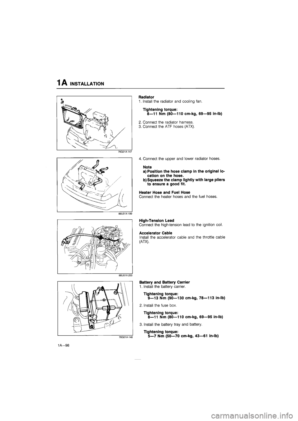
Radiator
1. Install the radiator and cooling fan.
Tightening torque:
8—11 N-m (80—110 cm-kg, 69—95 in-lb)
2. Connect the radiator harness.
3. Connect the ATF hoses (ATX).
4. Connect the upper and lower radiator hoses.
Note
a) Position the hose clamp in the original lo-
cation on the hose.
b) Squeeze the clamp lightly with large pliers
to ensure a good fit.
Heater Hose and Fuel Hose
Connect the heater hoses and the fuel hoses.
High-Tension Lead
Connect the high-tension lead to the ignition coil.
Accelerator Cable
Install the accelerator cable and the throttle cable
(ATX).
76G01A-148
Battery and Battery Carrier
1. Install the battery carrier.
Tightening torque:
9—13 N-m (90—130 cm-kg, 78—113 in-lb)
2. Install the fuse box.
Tightening torque:
8—11 N-m (80—110 cm-kg, 69—95 in-lb)
3. Install the battery tray and battery.
Tightening torque:
5_7 Nm (50—70 cm-kg, 43—61 in-lb)
1A—98
Page 134 of 1865

TROUBLESHOOTING GUIDE 1 B
SPECIFICATIONS
Engine model FE DOHC
Item Leaded fuel Unleaded fuel
Type Gasoline, 4 cycle
Cylinder arrangement and number In line, 4 cylinders
Combustion chamber Pentroof
Valve system OHC, belt driven
Displacement cc (cu in) 1,998 (121.9)
Bore and stroke mm (in) 86.0 x 86.0 (3.39 x 3.39)
Compression ratio 10.0 : 1 9.2 : 1
Compression pressure Standard 1,422 (14.5, 206)—290 1,373 (14.0, 199)—310
kPa (kg/cm2, psi)-rpm Minimum 996 (10.2, 144)—290 961 (9.8, 139)—310
IN Open BTDC 10° 10°
Valve timing
IN Close ABDC 60° 55° Valve timing
EX Open BBDC 60° 55° EX Close ATDC 10° 10°
Valve clearance mm (in) IN 0; Maintenance-free Valve clearance mm (in) EX 0; Maintenance-free
Idle speed rpm 750 ± 50
Ignition timing BTDC 12° ± 1°
Firing order 1—3--4-2
76G01B-002
TROUBLESHOOTING GUIDE
Problem Possible Cause Remedy Page
Difficult starting Malfunction of engine-related components
Burned valve
Worn piston, piston ring, or cylinder
Failed cylinder head gasket
Replace
Replace or repair Replace
1B—35 1B—43 1B—16
Malfunction of fuel system Refer to Section 4C
Malfunction of electrical system Refer to Section 5
Poor Idling Malfunction of engine-related components Malfunction of HLA
Poor valve to valve seat contact
Failed cylinder head gasket
Replace
Repair or replace
Replace
1B—60 1B—37 1B—16
Malfunction of fuel system Refer to Section 4C
Excessive oil
consumption Oil working up Worn piston ring groove or sticking piston ring Worn piston or cylinder
Replace
Replace or repair
1B-43 1B-43
Oil working down
Worn valve seal
Worn valve stem or guide
Replace
Replace 1B-35
Oil leakage Refer to Section 2A
76G01B-003
1B—3
Page 139 of 1865
TUNE-UP PROCEDURE 1 B
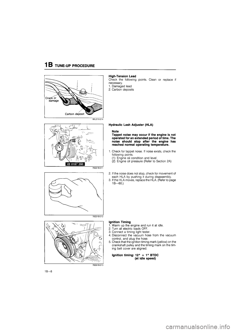
High-Tension Lead
Check the following points. Clean or replace if
necessary.
1. Damaged lead
2. Carbon deposits
86U01X-014
i^rrr ' /
49 0187 280
76G01B-011
76G01B-012
Hydraulic Lash Adjuster (HLA)
Note
Tappet noise may occur if the engine is not
operated for an extended period of time. The
noise should stop after the engine has
reached normal operating temperature.
1. Check for tappet noise. If noise exists, check the
following points.
(1) Engine oil condition and level
(2) Engine oil pressure (Refer to Section 2A)
2. If the noise does not stop, check for movement of
each HLA by pushing it during disassembly.
3. If the HLA moves, replace the HLA. (Refer to page
1B—60.)
Ignition Timing
1. Warm up the engine and run it at idle.
2. Turn all electric loads OFF.
3. Connect a timing light tester.
4. Disconnect the vacuum hose from the vacuum
control, and plug the hose.
5. Check that the ignition timing mark (yellow) on the
crankshaft pulley and the timing mark on the tim-
ing belt cover are aligned.
Ignition timing: 12° ± 1° BTDC
(at idle speed)
76G01B-008
1B—8
Page 140 of 1865
TUNE-UP PROCEDURE 1 B
76G01B-015
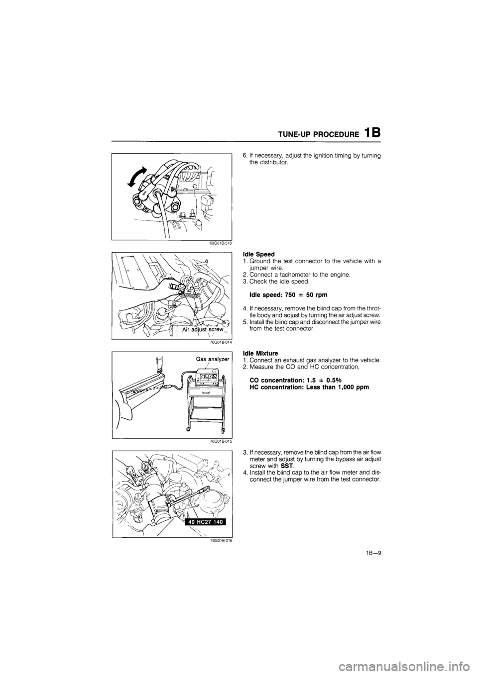
6. If necessary, adjust the ignition timing by turning
the distributor.
Idle Speed
1. Ground the test connector to the vehicle with a
jumper wire.
2. Connect a tachometer to the engine.
3. Check the idle speed.
Idle speed: 750 ± 50 rpm
4. If necessary, remove the blind cap from the throt-
tle body and adjust by turning the air adjust screw.
5. Install the blind cap and disconnect the jumper wire
from the test connector.
Idle Mixture
1. Connect an exhaust gas analyzer to the vehicle.
2. Measure the CO and HC concentration.
CO concentration: 1.5 ± 0.5%
HC concentration: Less than 1,000 ppm
3. If necessary, remove the blind cap from the air flow
meter and adjust by turning the bypass air adjust
screw with SST.
4. Install the blind cap to the air flow meter and dis-
connect the jumper wire from the test connector.
76G01B-016
1B—9
Page 141 of 1865
1 B ON-VEHICLE INSPECTION
76G01B-017
86U01X-020
76G01B-018
Possible Cause
ON-VEHICLE INSPECTION
If the engine exhibits low power, poor fuel economy,
or poor idle, check the following points.
1. Ignition system (Refer to Section 5)
2. Compression
3. Fuel system (Refer to Section 4C)
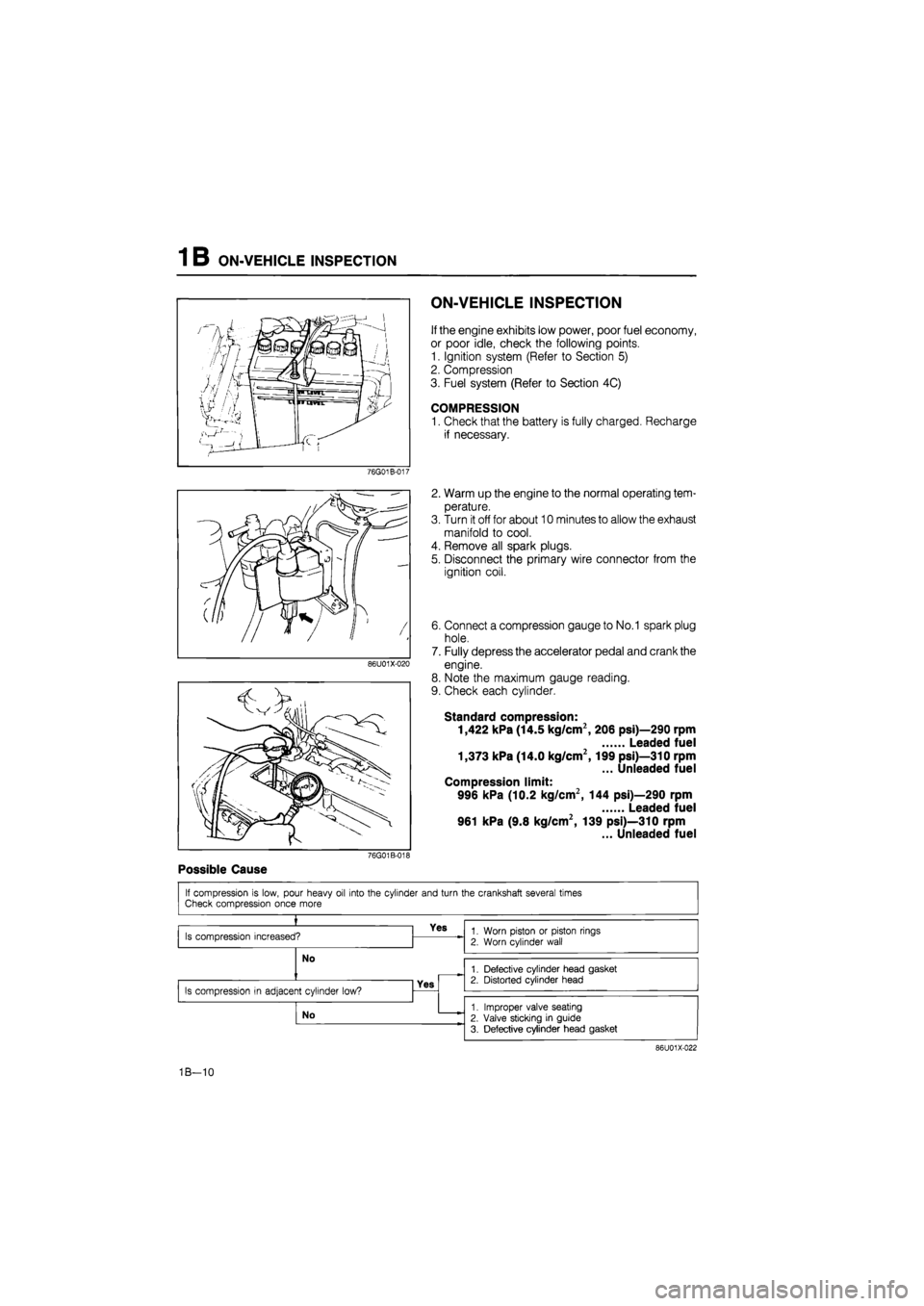
COMPRESSION
1. Check that the battery is fully charged. Recharge
if necessary.
2. Warm up the engine to the normal operating tem-
perature.
3. Turn it off for about 10 minutes to allow the exhaust
manifold to cool.
4. Remove all spark plugs.
5. Disconnect the primary wire connector from the
ignition coil.
6. Connect a compression gauge to No.1 spark plug
hole.
7. Fully depress the accelerator pedal and crank the
engine.
8. Note the maximum gauge reading.
9. Check each cylinder.
Standard compression:
1,422 kPa (14.5 kg/cm2, 206 psi)—290 rpm
Leaded fuel
1,373 kPa (14.0 kg/cm2,199 psi)—310 rpm
... Unleaded fuel
Compression limit:
996 kPa (10.2 kg/cm2, 144 psi)—290 rpm
Leaded fuel
961 kPa (9.8 kg/cm2, 139 psi)—310 rpm
... Unleaded fuel
If compression is low, pour heavy oil into the cylinder and turn the crankshaft several times Check compression once more
»
Is compression increased? Yes 1. Worn piston or piston rings
2. Worn cylinder wall
No
1. Worn piston or piston rings
2. Worn cylinder wall
No 1. Defective cylinder head gasket 2. Distorted cylinder head
Is compression in adjacent cylinder low? Yes
1. Defective cylinder head gasket 2. Distorted cylinder head
Is compression in adjacent cylinder low?
No 1. Improper valve seating
2. Valve sticking in guide
3. Defective cylinder head gasket
86U01X-022
1B—10
Page 211 of 1865
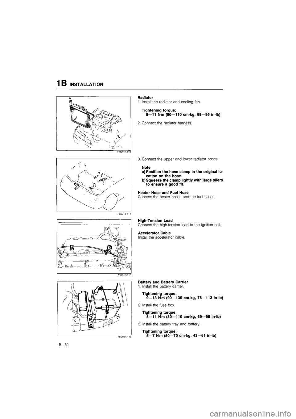
1B INSTALLATION
76G01B-113
76G01B-114
76G01B-115
Radiator
1. Install the radiator and cooling fan.
Tightening torque:
8—11 N-m (80—110 cm-kg, 69—95 in-lb)
2. Connect the radiator harness.
3. Connect the upper and lower radiator hoses.
Note
a) Position the hose clamp in the original lo-
cation on the hose.
b) Squeeze the clamp lightly with large pliers
to ensure a good fit.
Heater Hose and Fuel Hose
Connect the heater hoses and the fuel hoses.
High-Tension Lead
Connect the high-tension lead to the ignition coil.
Accelerator Cable
Install the accelerator cable.
76G01A-148
Battery and Battery Carrier
1. Install the battery carrier.
Tightening torque:
9—13 N-m (90—130 cm-kg, 78—113 in-lb)
2. Install the fuse box.
Tightening torque:
8—11
N
m (80—110 cm-kg, 69—95 in-lb)
3. Install the battery tray and battery.
Tightening torque:
5_7
N m
(50—70 cm-kg, 43—61 in-lb)
1B—80
Page 351 of 1865

3A COOLING FAN
COOLING FAN
SYSTEM CIRCUIT
IG1 IG Relay
*
No.1
relay
Water thermo switch
I With A/C
CM)
Main fan
1
L..±
No.2
relay
IG2
Add.
relay ol
(M)
A/C sw.
Add fan
86U03X-019
CIRCUIT INSPECTION
1. Turn the ignition switch ON.
2. Disconnect the water thermo switch connector, and
check that the fan operates.
3. If the fan doesn't operate, check the fuse, fan re-
lay, fan motor, thermo switch and wiring harness.
76G03A-010
3 A—12
Page 353 of 1865

3A COOLING FAN
WATER THERMO SWITCH
1. Remove the cooling fan water thermo switch.
Note
Make sure that the ignition switch is OFF. If
not, the fan will operate when the connector
is removed.
76G03A-013
76G03A-014
Place the water thermo switch in water.
Heat the water gradually, and check for continui-
ty of the switch with an ohmmeter. Replace if
necessary.
Water thermo switch (ON OFF):
97°C (207°F)....ECE, Hong Kong, Singapore
91
°C (196°F)....General, Middle East
Install the water thermo switch and a new O-ring.
Caution
Do not use sealing tape.
3 A—14