engine MAZDA 626 1987 Workshop Manual
[x] Cancel search | Manufacturer: MAZDA, Model Year: 1987, Model line: 626, Model: MAZDA 626 1987Pages: 1865, PDF Size: 94.35 MB
Page 665 of 1865

4C CONTROL SYSTEM
Jjf (Terminal A)
n PI
WRED r^j
BLACK
BLACK 1 (Terminal C)
76G04C-189
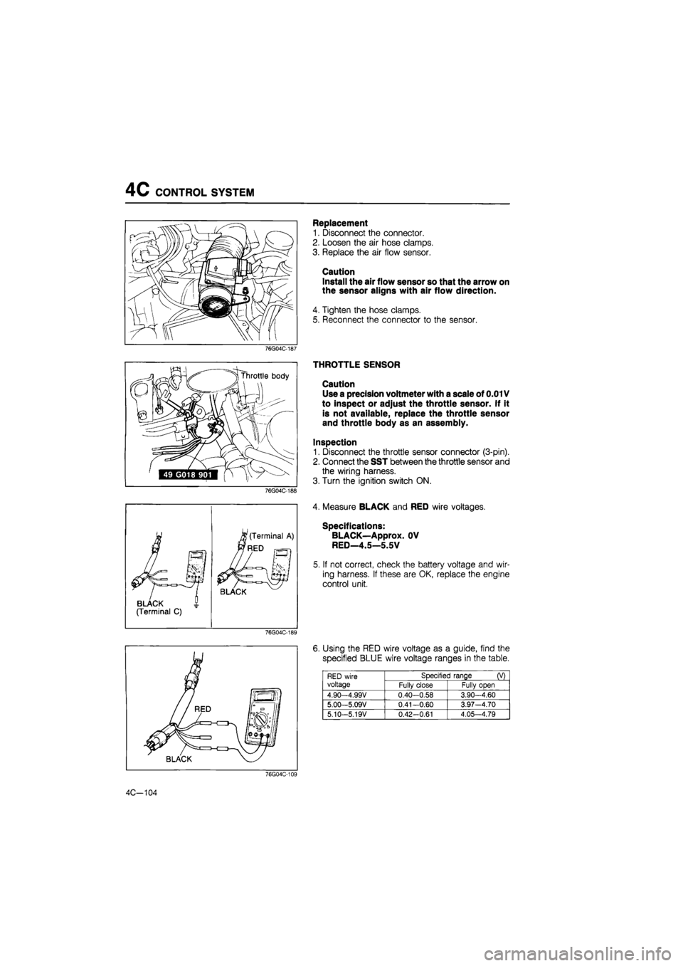
Replacement
1. Disconnect the connector.
2. Loosen the air hose clamps.
3. Replace the air flow sensor.
Caution
Install the air flow sensor so that the arrow on
the sensor aligns with air flow direction.
4. Tighten the hose clamps.
5. Reconnect the connector to the sensor.
THROTTLE SENSOR
Caution
Use a precision voltmeter with a scale of 0.01V
to inspect or adjust the throttle sensor. If it
is not available, replace the throttle sensor
and throttle body as an assembly.
Inspection
1. Disconnect the throttle sensor connector (3-pin).
2. Connect the SST between the throttle sensor and
the wiring harness.
3. Turn the ignition switch ON.
4. Measure BLACK and RED wire voltages.
Specifications:
BLACK—Approx. OV
RED—4.5—5.5V
5. If not correct, check the battery voltage and wir-
ing harness. If these are OK, replace the engine
control unit.
6. Using the RED wire voltage as a guide, find the
specified BLUE wire voltage ranges in the table.
RED wire voltage
Specified range (V) RED wire voltage Fully close Fully open
4.90—4.99V 0.40-0.58 3.90-4.60
5.00—5.09V 0.41—0.60 3.97-4.70
5.10-5.19V 0.42—0.61 4.05—4.79
4C-104
Page 668 of 1865

CONTROL SYSTEM 4C
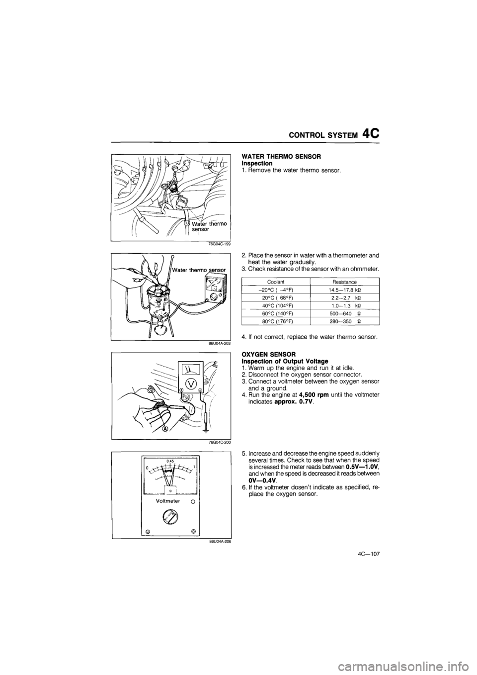
WATER THERMO SENSOR
Inspection
1. Remove the water thermo sensor.
76G04C-199
86U04A-203
2. Place the sensor in water with a thermometer and
heat the water gradually.
3. Check resistance of the sensor with an ohmmeter.
Coolant Resistance
-20°C ( —4°F) 14.5—17.8 kfl
20°C ( 68°F) 2.2-2.7 kQ
40°C (104°F) 1.0—1.3 kQ
60°C (140°F) 500—640 O
80°C (176°F) 280—350 fl
4. If not correct, replace the water thermo sensor.
OXYGEN SENSOR
Inspection of Output Voltage
1. Warm up the engine and run it at idle.
2. Disconnect the oxygen sensor connector.
3. Connect a voltmeter between the oxygen sensor
and a ground.
4. Run the engine at 4,500 rpm until the voltmeter
indicates approx. 0.7V.
76G04C-200
5. Increase and decrease the engine speed suddenly
several times. Check to see that when the speed
is increased the meter reads between 0.5V—1 .OV,
and when the speed is decreased it reads between
OV—0.4V.
6. If the voltmeter dosen't indicate as specified, re-
place the oxygen sensor.
86U04A-206
4C—107
Page 669 of 1865

4C CONTROL SYSTEM
Check connector: Green (6 pin)
cable
49 H018 9A1
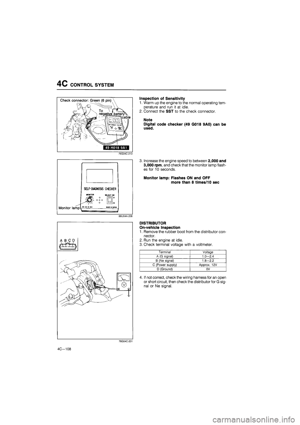
Inspection of Sensitivity
1. Warm up the engine to the normal operating tem-
perature and run it at idle.
2. Connect the SST to the check connector.
Note
Digital code checker (49 G018 9A0) can be
used.
76G04C-213
Increase the engine speed to between 2,000 and
3,000 rpm, and check that the monitor lamp flash-
es for 10 seconds.
Monitor lamp: Flashes ON and OFF
more than 8 times/10 sec
86U04A-208
A B C D
/llkw^ - ®
I « ^
76G04C-201
4C—108
DISTRIBUTOR
On-vehicle Inspection
1. Remove the rubber boot from the distributor con-
nector.
2. Run the engine at idle.
3. Check terminal voltage with a voltmeter.
Terminal Voltaae
A (G signal) 1.0—2.4
B (Ne sianaB 1.8—2.2
C (Power supply) Approx. 12V
D (Ground) OV
4. If not correct, check the wiring harness for an open
or short circuit, then check the distributor for G sig-
nal or Ne signal.
Page 670 of 1865

CONTROL SYSTEM 4C
76G04C-203
76G04C-204
76G04C-205
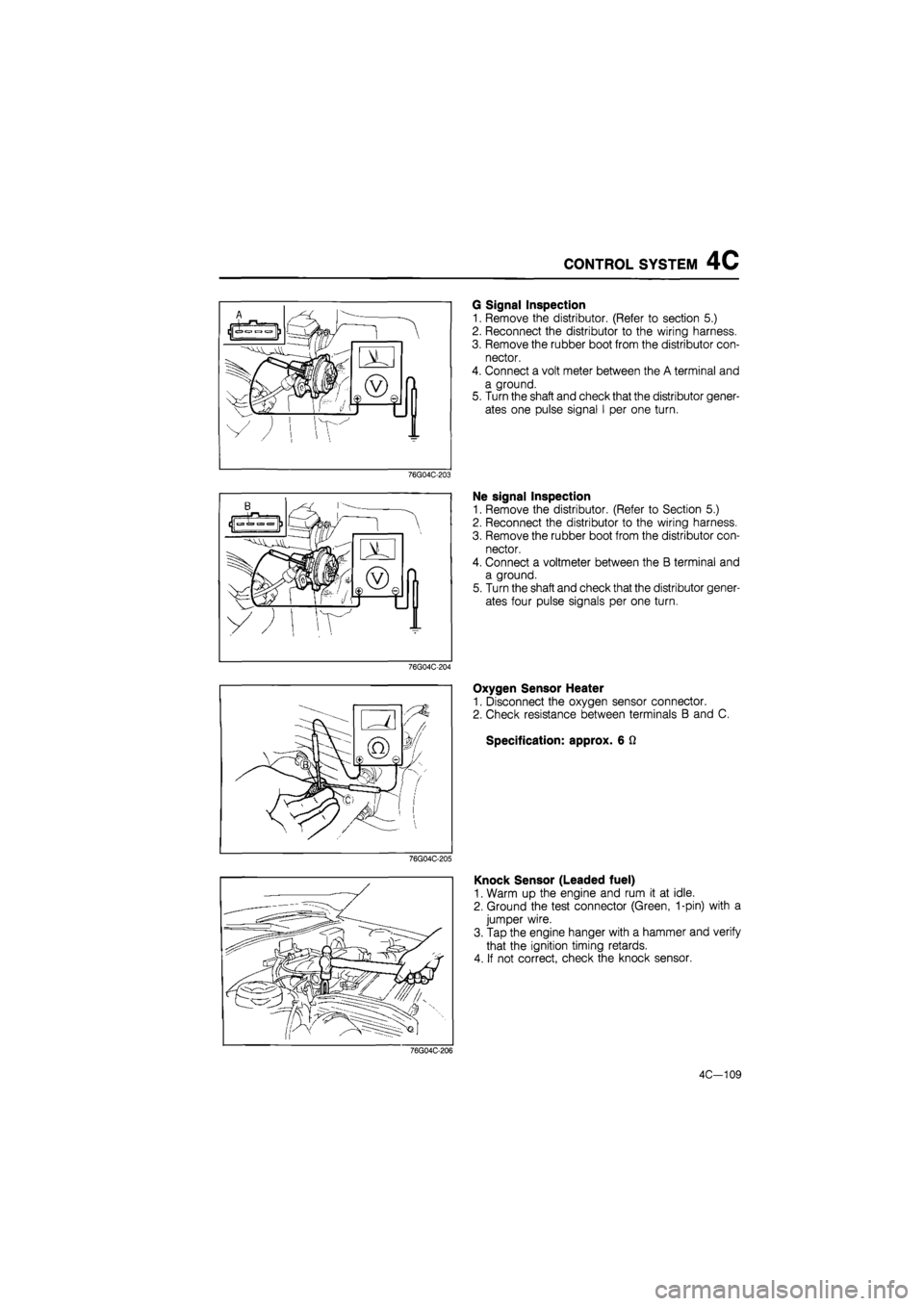
G Signal Inspection
1. Remove the distributor. (Refer to section 5.)
2. Reconnect the distributor to the wiring harness.
3. Remove the rubber boot from the distributor con-
nector.
4. Connect a volt meter between the A terminal and
a ground.
5. Turn the shaft and check that the distributor gener-
ates one pulse signal I per one turn.
Ne signal Inspection
1. Remove the distributor. (Refer to Section 5.)
2. Reconnect the distributor to the wiring harness.
3. Remove the rubber boot from the distributor con-
nector.
4. Connect a voltmeter between the B terminal and
a ground.
5. Turn the shaft and check that the distributor gener-
ates four pulse signals per one turn.
Oxygen Sensor Heater
1. Disconnect the oxygen sensor connector.
2. Check resistance between terminals B and C.
Specification: approx. 6 Q
Knock Sensor (Leaded fuel)
1. Warm up the engine and rum it at idle.
2. Ground the test connector (Green, 1-pin) with a
jumper wire.
3. Tap the engine hanger with a hammer and verify
that the ignition timing retards.
4. If not correct, check the knock sensor.
76G04C-206
4C-109
Page 673 of 1865

4D OUTLINE
OUTLINE
The Mazda 626 offers two diesel engines; a Comprex supercharged RF-CX engine, and a normally
aspirated RF-N engine.
SPECIFICATIONS
—Engine model
Item ———
ECE UK, GENERAL —Engine model
Item ——— RF-CX RF-N
Fuel tank Capacity liters (US gal, Imp gal) 60 (15.9, 13.2)
Fuel filter Type Cartridge, paper element
Sedimenter Type With detector
Injection pump
Type Bosch VE distributor
Injection pump
Manufacturer Diesel Kiki Co,, Ltd.
Injection pump
Direction of rotation Clockwise Injection pump
Drive method Timing belt
Injection pump
Plunger diameter mm (in) 9.0 (0.35) 8.0 (0.31)
Injection pump
Cam lift mm (in) 2.2 (0.087)
Injection nozzle Type Throttle Injection nozzle
Injection pressure kPa (kg/cm2, psi) 13,240 (135 , 1,920)
Injection timing ATDC
1
° TDC 0°
Idle speed rpm 720 _+f0
Fast idle speed (A/C ON) rpm 700-750
Cold start device Engine speed rpm 1.100 Cold start device
Advance degree 6°
Air cleaner Type Cartridge, paper element Air cleaner Type
Wet Dry
PCV system Type Open Closed
76G04D-002
4D—2
Page 674 of 1865

TROUBLESHOOTING GUIDE 4D
TROUBLESHOOTING GUIDE
Condition Condition Cause Remedy
Hard starting Fuel filter
Clogged Replace
Water or air in filter Repair
Fuel injection pump Faulty fuel cut solenoid Replace Incorrect injection timing Adjust
Air in pump Bleed
Faulty pump Replace
Fuel injection nozzle Seized needle valve Replace
Fuel dripping from nozzle Replace Incorrect valve opening pressure Adjust
Faulty glow plug Replace
Faulty cold start device Adjust or replace
Faulty supercharging system Refer to page 4D—10
Rough idle Fuel filter (Refer to "Hard starting") Fuel injection pump (Refer to "Hard starting")
Fuel injection nozzle
Seized needle valve Replace
Incorrect valve opening pressure Adjust
Improper mounting to nozzle holder Repair
Leakage of nozzle holder copper washer Replace
Fuel injection pipe Cranks Replace
Leaking from joint Repair
Improper idle speed adjustment Adjust
Engine knocking Incorrect injection timing Adjust
Low quality fuel Replace
Incorrect injection nozzle opening pressure Ajust
Seized injection nozzle needle valve Replace
Fuel dripping from injection nozzle Replace
Faulty supercharging system Refer to page 4D—10
High fuel Fuel injection pump consumption Incorrect injection timing Adjust consumption High idle speed Adjust, Inspect the dashpot
Fuel injection nozzle Incorrect valve opening pressure Repair
Fuel dripping from nozzle Replace
Leakage of nozzle holder copper washer Replace
Fuel leaking from connection Repair
Clogged fuel filter Replace
Clogged air cleaner Replace
Poor acceleration Fuel injection nozzle (Refer to "Hard starting")
Fuel injection pump (Refer to "Hard starting")
Fuel injection pipe (Refer to "Rough idle") Fuel filter (Refer to "Hard starting") Clogged air cleaner Clean or replace
Faulty supercharging system Refer to page 4D—10
Excessive exhaust Clogged air cleaner Clean or replace
smoke Improper injection timig Adjust
Faulty nozzle or nozzle holder Adjust or replace
Faulty supercharging system Refer to page 4D—10
76G04D-003
4D-3
Page 677 of 1865

4D ON-VEHICLE MAINTENANCE
IDLE SPEED
1. Warm up the engine to normal operating tem-
perature.
2. Be sure the A/C switch is OFF.
3. Connect a tachometer and check the engine
speed.
Idle speed: 720 :
20
rpm
76G04D-012
4. If necessary, adjust the idle by turning the idle ad-
justing screw.
76G04D-013
Fast Idle Speed (A/C equipped model)
1. Turn ON the A/C switch and blower motor switch.
2. Check the engine speed.
Fast idle speed: 725 ± 25 rpm
3. If necessary, turn the adjusting screw on the idle-
up actuator, and adjust the fast idle speed.
76G04D-014
EXHAUST SMOKE
Increase and decrease the engine speed several
times and check that there is no black smoke.
If
there
is, refer to the Troubleshooting Guide.
76G04D-015
4D—6
Page 681 of 1865

4D SUPERCHARGING SYSTEM (RF-CX)
SUPERCHARGING SYSTEM (RF-CX)
TROUBLESHOOTING GUIDE
Engine
hard
starting
Poor
acceleration
Excessive
blue
smoke
Excessive
black
smoke
Excessive
compressed
air
temperature
(Buzzser
sounds)
Excessive
noise
Possible Cause Remedy (reference page)
*
*
Comprex supercharger Rotor stuck Casing damaged Rotor bearing damaged
Replace (4D—14)
* * * Drive system
of
Comprex supercharger Drive belt loose
or
worn Repair
or
replace
(4D-12) * Idler pulley damaged
Repair
or
replace
(4D-12) * Pulley bolt loose
or
worn
Repair
or
replace
(4D-12)
* Wastegate
Valve
not
open Clean
or
repace (4D-12) ik * Valve
not
closed
Clean
or
repace (4D-12)
* * Starting valve
Valve
not
open Repair
or
replace (4D-15)
* * Valve
not
closed
Repair
or
replace (4D-15) * Bypass valve
not
open
Repair
or
replace (4D-15)
* * Bypass valve
not
closed
Repair
or
replace (4D-15)
* Intercooler dirty Clean
or
replace (4D-16)
* * * * Intake
air
system Fresh
air
side clogged (Air cleaner
ele-
ment,
etc.)
Repair
or
replace * Compressed
air
side clogged (Intercool-
er,
etc.)
Repair
or
replace
* Fresh
air
side leaks
Repair
or
replace
* * * Compressed
air
side leaks
Repair
or
replace
* Exhaust system
Exhaust
gas
breaked Repair
* * * * * Exhaust pipe clogged
Repair
* Silencer damaged
(in
fender,
in air
clean-er,
in air
funnel, Comprex insulator) Repair
or
replace
* Bolt
and nut
loosend Repair
76G04D-022
4D—10
Page 682 of 1865

4D SUPERCHARGING SYSTEM (RF-CX)
ON-VEHICLE INSPECTION
Boost Pressure
1. Connect a pressure gauge to the hose from the
intake manifold.
2. (On chassis dynomometer, full load)
(1) Set the vehicle on a chassis dynomometer.
(2) Run the vehicle in gear at 3,000 rpm with the
acceleration pedal fully depressed.
(3) Measure the boost pressure.
Boost pressure:
82 kPa (0.87 kg/cm2, 8.1 psi)
Note
The above inspection should be done on a
chassis dynomometer. If a dynomometer is
not available follow the below procedure.
3. (Off chassis dynomometer, no load)
(1) Shift the transaxle out off gear.
(2) Run the engine in neutral at 3,000 rpm of the
engine no load.
Measure the boost pressure.
Boost pressure:
5 kPa (0.05 kg/cm2, 0.7 psi)
Note
The boost pressure is varied by engine speed
and engine load.
(3) Remove the starting valve bypass hose.
(4) Check that the bypass valve is closed at 3,000
rpm.
4.
If
the pressure is below specification, check the fol-
lowing. Replace the Comprex supercharger if
necessary.
(1) Intake air and exhaust passages leakage
(2) Intake air and exhaust passages clogged
(3) Wastegate (Refer to 4D—12.)
(4) Starting valve (Refer to 4D—15.)
(5) Fuel system (Injection nozzle... refer to page
4D—31, injection pump...refer to page 4D—24,
etc.)
5. If the pressure exceeds specification, check the
wastegate operation. (Refer to page 4D—12.)
4D—11
Page 695 of 1865

4D FUEL SYSTEM
INJECTION PUMP
On-Vehicle Inspection
Fuel cut solenoid valve
1. Run the engine at idle.
2. Disconnect the solenoid valve connector, and let
the engine stop.
3. If the engine does not stop, replace the fuel cut
solenoid valve.
76G04D-055
Pick up coil
1. Disconnect the pick up coil connector.
2. Check for continuity of the coil using an ohmmeter.
3. Replace it if there is not continuity.
76G04D-056
O
o
>=
=<
t= —i V
' 1 -4
n
5-
U
o
1 mm (0.39 in) Injection Timing Adjustment
Inspection
Check the injection timing. (Refer to page 4D—5.)
Injection timing
RF-CX: ATDC 10
RF-N : TDC 0°
76G04D-057
Adjustment
1. Loosen the injection pump mounting nut.
2. Loosen the injection pump bracket bolt.
76G04D-058
4D—24