check engine MAZDA 626 1987 Owner's Guide
[x] Cancel search | Manufacturer: MAZDA, Model Year: 1987, Model line: 626, Model: MAZDA 626 1987Pages: 1865, PDF Size: 94.35 MB
Page 217 of 1865
TUNE-UP PROCEDURE 1C
4BG01 B-006
4BG01B-007
76G01C-237
TUNE-UP PROCEDURE
Turn the engine according to the procedures
described below.
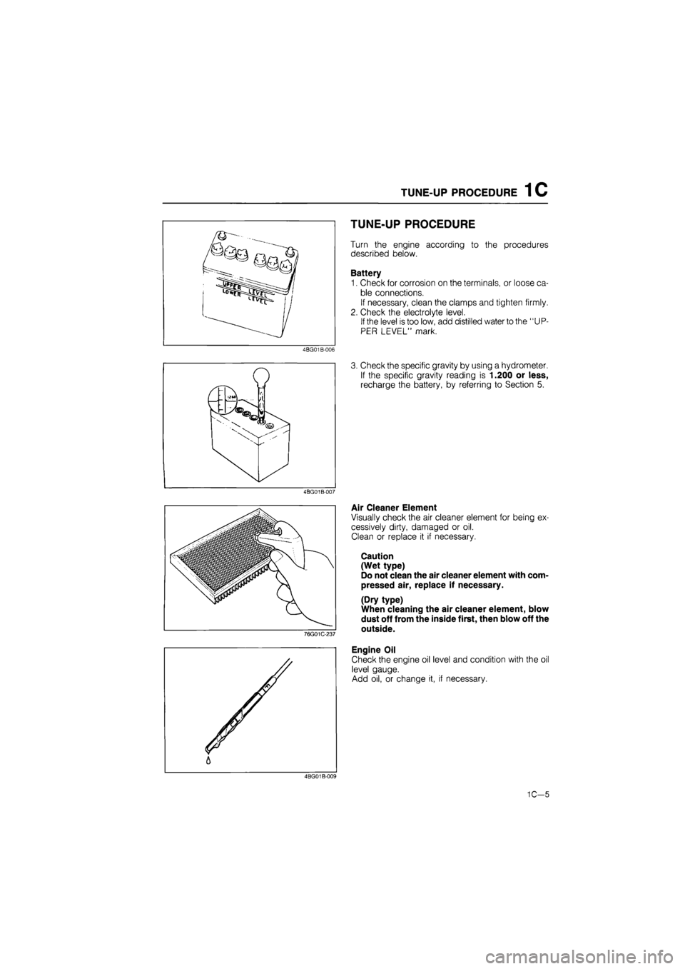
Battery
1. Check for corrosion on the terminals, or loose ca-
ble connections.
If necessary, clean the clamps and tighten firmly.
2. Check the electrolyte level.
If the level is too low, add distilled water to the "UP-
PER LEVEL" mark.
3. Check the specific gravity by using a hydrometer.
If the specific gravity reading is 1.200 or less,
recharge the battery, by referring to Section 5.
Air Cleaner Element
Visually check the air cleaner element for being ex-
cessively dirty, damaged or oil.
Clean or replace it if necessary.
Caution
(Wet type)
Do not clean the air cleaner element with com-
pressed air, replace if necessary.
(Dry type)
When cleaning the air cleaner element, blow
dust off from the inside first, then blow off the
outside.
Engine Oil
Check the engine oil level and condition with the oil
level gauge.
Add oil, or change it, if necessary.
4BG01B-009
1C—5
Page 218 of 1865
1C TUNE-UP PROCEDURE
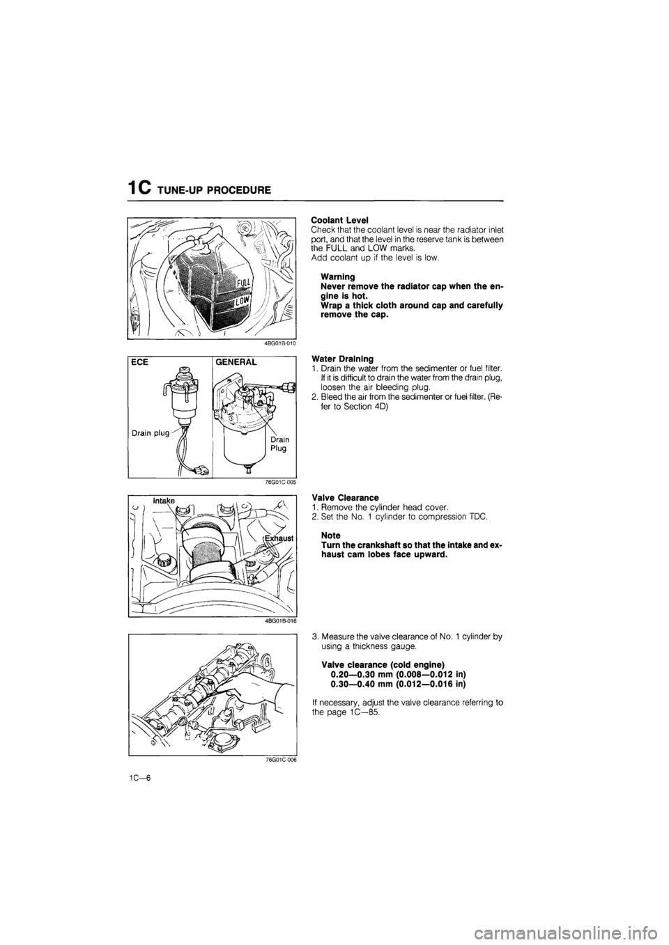
Coolant Level
Check that the coolant level is near the radiator inlet
port, and that the level in the reserve tank is between
the FULL and LOW marks.
Add coolant up if the level is low.
Warning
Never remove the radiator cap when the en-
gine is hot.
Wrap a thick cloth around cap and carefully
remove the cap.
4BG01B-010
Water Draining
1. Drain the water from the sedimenter or fuel filter.
If it is difficult to drain the water from the drain plug,
loosen the air bleeding plug.
2. Bleed the air from the sedimenter or fuel filter. (Re-
fer to Section 4D)
76G01C-005
Valve Clearance
1. Remove the cylinder head cover.
2. Set the No. 1 cylinder to compression TDC.
Note
Turn the crankshaft so that the intake and ex-
haust cam lobes face upward.
4BG01B-016
3. Measure the valve clearance of No. 1 cylinder by
using a thickness gauge.
Valve clearance (cold engine)
0.20—0.30 mm (0.008—0.012 in)
0.30—0.40 mm (0.012—0.016 in)
If necessary, adjust the valve clearance referring to
the page 1C—85.
76G01C-006
1C-6
Page 221 of 1865
TUNE-UP PROCEDURE 1C
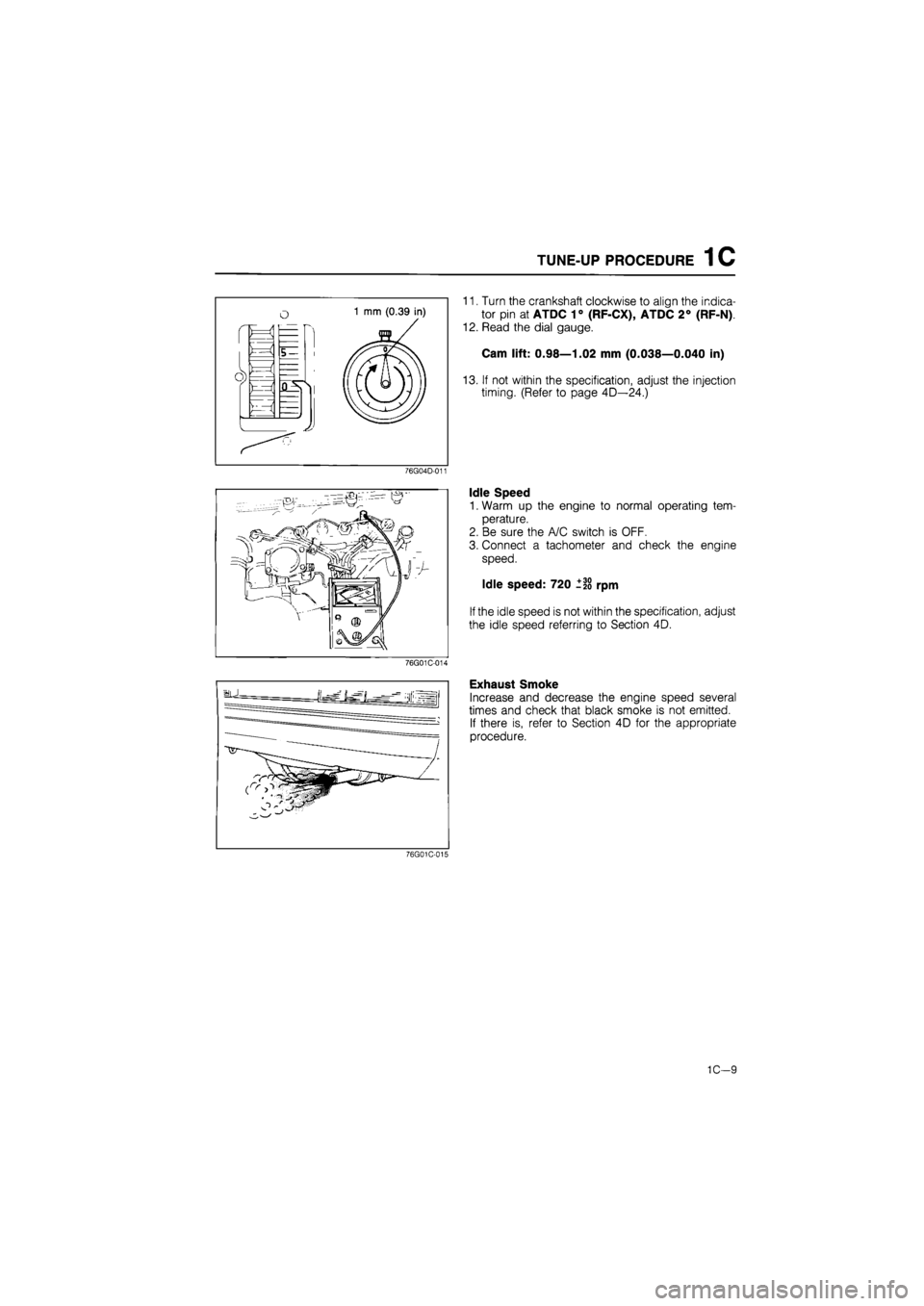
11. Turn the crankshaft clockwise to align the indica-
tor pin at ATDC 1° (RF-CX), ATDC 2° (RF-N)
12. Read the dial gauge.
Cam lift: 0.98—1.02 mm (0.038—0.040 in)
13. If not within the specification, adjust the injection
timing. (Refer to page 4D—24.)
76G04D-011
Idle Speed
1. Warm up the engine to normal operating tem-
perature.
2. Be sure the A/C switch is OFF.
3. Connect a tachometer and check the engine
speed.
Idle speed: 720 ±20 rpm
If the idle speed is not within the specification, adjust
the idle speed referring to Section 4D.
76G01C-014
Exhaust Smoke
Increase and decrease the engine speed several
times and check that black smoke is not emitted.
If there is, refer to Section 4D for the appropriate
procedure.
76G01C-015
1C—9
Page 222 of 1865
1C ON-VEHICLE INSPECTION
ON-VEHICLE INSPECTION
If the engine exhibits low power, poor fuel economy,
or poor idle, check the following:
1. Compression
2. Fuel system (Refer to Section 4D)
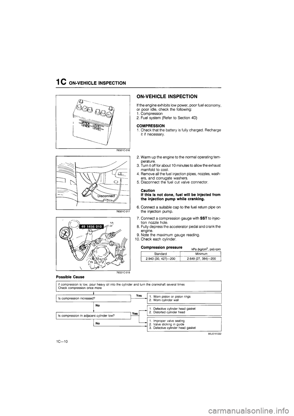
COMPRESSION
1. Check that the battery is fully charged, Recharge
it if necessary.
76G01C-016
76G01C-017
2. Warm up the engine to the normal operating tem-
perature.
3. Turn it off for about 10 minutes to allow the exhaust
manifold to cool.
4. Remove all the fuel injection pipes, nozzles, wash-
ers, and corrugate washers.
5. Disconnect the fuel cut valve connector.
Caution
If this is not done, fuel will be injected from
the injection pump while cranking.
6. Connect a suitable cap to the fuel return pipe on
the injection pump.
7. Connect a compression gauge with SST to injec-
tion nozzle hole.
8. Fully depress the accelerator pedal and crank the
engine.
9. Note the maximum gauge reading.
10. Check each cylinder.
Compression pressure kPa (kg/cm2, psi)-rpm
Standard Minimum
2.943 (30, 427)—200 2.649 (27, 384)—200
76G01C-018
Possible Cause
86U01X-022
1C-10
Page 227 of 1865
ON-VEHICLE MAINTENANCE (TIMING BELT) 1 C
76G01C-027
76G01C-028
76G01C-029
Checking
point
Idler pulley
Crankshaft pulley zQi A/C
Checking point compressor
76G01C-030
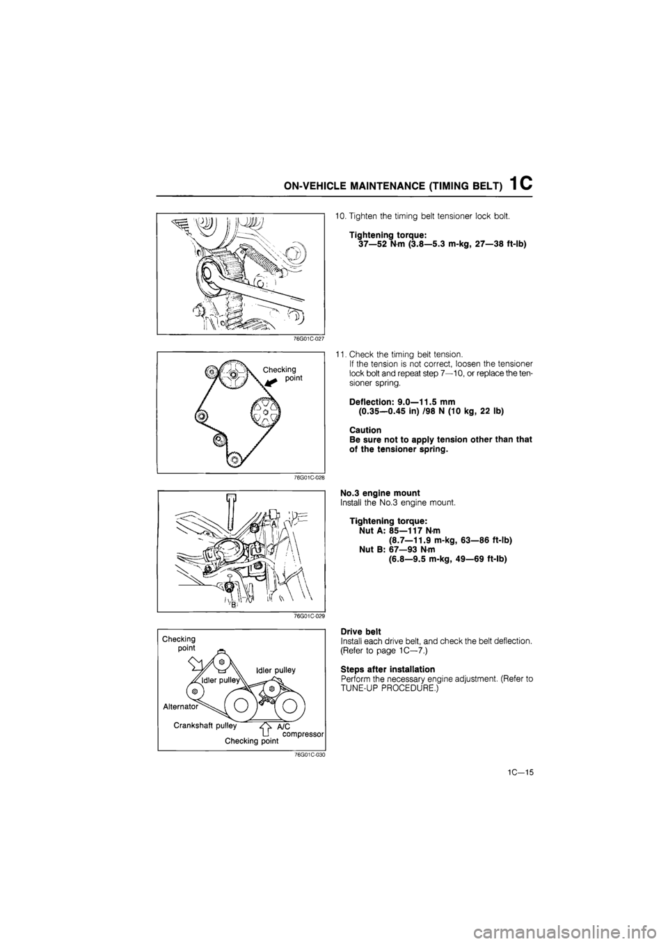
10. Tighten the timing belt tensioner lock bolt.
Tightening torque:
37—52
N
m (3.8—5.3 m-kg, 27—38 ft-lb)
11. Check the timing belt tension.
If the tension is not correct, loosen the tensioner
lock bolt and repeat step 7—10, or replace the ten-
sioner spring.
Deflection: 9.0—11.5 mm
(0.35—0.45 in) /98 N (10 kg, 22 lb)
Caution
Be sure not to apply tension other than that
of the tensioner spring.
No.3 engine mount
Install the No.3 engine mount.
Tightening torque:
Nut A: 85—117 N-m
(8.7—11.9 m-kg, 63—86 ft-lb)
Nut B: 67—93 N-m
(6.8—9.5 m-kg, 49—69 ft-lb)
Drive belt
Install each drive belt, and check the belt deflection.
(Refer to page 1C—7.)
Steps after installation
Perform the necessary engine adjustment. (Refer to
TUNE-UP PROCEDURE,)
1C-15
Page 235 of 1865
ON-VEHICLE MAINTENANCE (CYLINDER HEAD) 1 C
76G01C-049
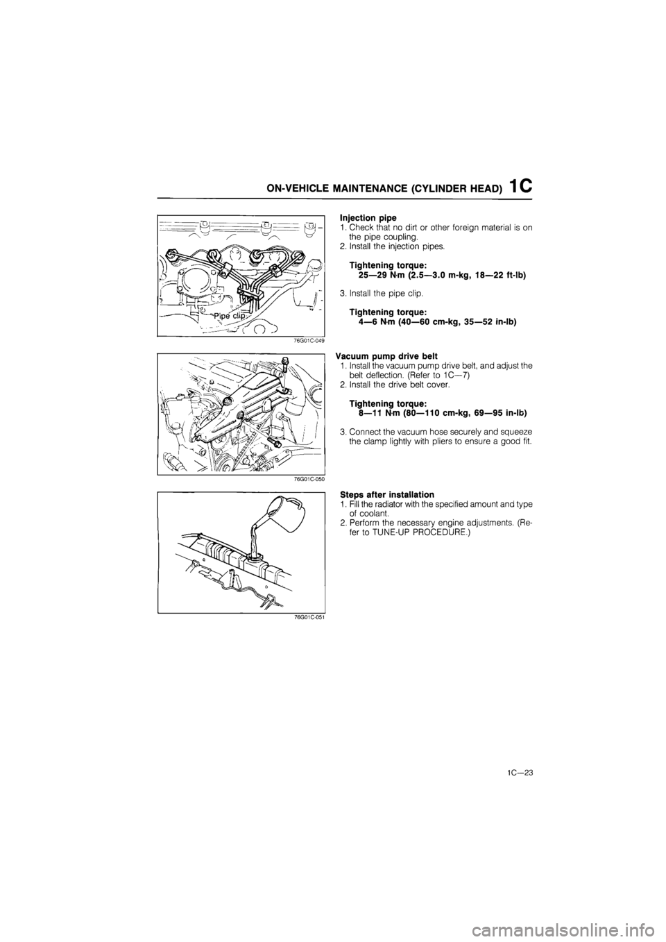
Injection pipe
1. Check that no dirt or other foreign material is on
the pipe coupling.
2. Install the injection pipes.
Tightening torque:
25—29 Nm (2.5—3.0 m-kg, 18—22 ft-lb)
3. Install the pipe clip.
Tightening torque:
4—6 N-m (40—60 cm-kg, 35—52 in-lb)
Vacuum pump drive belt
1. Install the vacuum pump drive belt, and adjust the
belt deflection. (Refer to 1C—7)
2. Install the drive belt cover.
Tightening torque:
8—11 Nm (80—110 cm-kg, 69—95 in-lb)
3. Connect the vacuum hose securely and squeeze
the clamp lightly with pliers to ensure a good fit.
76G01C-050
Steps after installation
1. Fill the radiator with the specified amount and type
of coolant.
2. Perform the necessary engine adjustments. (Re-
fer to TUNE-UP PROCEDURE.)
76G01C-051
1C—23
Page 242 of 1865
1 C ON-VEHICLE MAINTENANCE (VALVE SEAL)
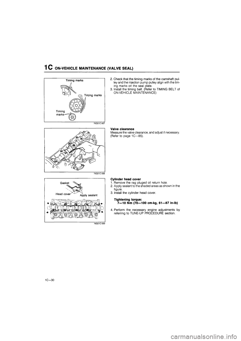
2. Check that the timing marks of the camshaft pul-
ley and the injection pump pulley align with the tim-
ing marks on the seal plate.
3. Install the timing belt. (Refer to TIMING BELT of
ON-VEHICLE MAINTENANCE)
76G01C-067
Valve clearance
Measure the valve clearance, and adjust if necessary.
(Refer to page 1C—85).
76G01C-068
Gasket
Head cover App|y sealant
Cylinder head cover
1. Remove the rag pluged oil return hole.
2. Apply sealant to the shaded areas as shown in the
figure.
3. Install the cylinder head cover.
Tightening torque:
7—10 Nm (70—100 cm-kg, 61—87 in-lb)
4. Perform the necessary engine adjustments by
referring to TUNE-UP PROCEDURE section.
76G01C-069
1C-30
Page 270 of 1865
INSPECTION AND REPAIR 1C
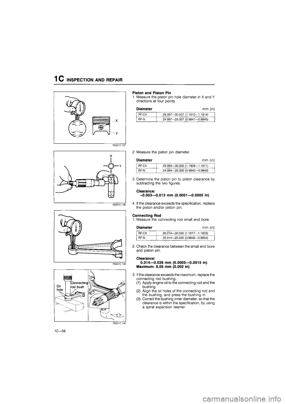
Piston and Piston Pin
1. Measure the piston pin hole diameter in X and Y
directions at four points.
Diameter mm (in)
RF-CX 29.997-30.007 (1.1810-1.1814)
RF-N 24.997-25.007 (0.9841-0.9845)
76G01C-137
76G01C-139
2. Measure the piston pin diameter.
Diameter mm (in)
RF-CX 29.994-30.000 (1.1809-1.1811)
RF-N 24.994-25.000 (0.9840-0.9843)
3. Determine the piston pin to piston clearance by
subtracting the two figures.
Clearance-
-0.003—0.013 mm (0.0001—0.0005 in)
4. If the clearance exceeds the specification, replace
the piston and/or piston pin.
Connecting Rod
1. Measure the connecting rod small end bore.
Diameter mm (in)
RF-CX 30.014-30.030 (1.1817-1.1823)
RF-N 25.014-25.030 (0.9848-0.9854)
2. Check the clearance between the small end bore
and piston pin.
Clearance*
0.014—0.036 mm (0.0005—0.0015 in)
Maximum: 0.05 mm (0.002 in)
3. If the clearance exceeds the maximum, replace the
connecting rod bushing.
(1) Apply engine oil to the connecting rod and the
bushing.
(2) Align the oil holes of the connecting rod and
the bushing, and press the bushing in.
(3) Correct the bushing inner diameter, so that the
clearance is within the specification, by using
a spiral expansion reamer.
76G01C-144
1C-58
Page 277 of 1865
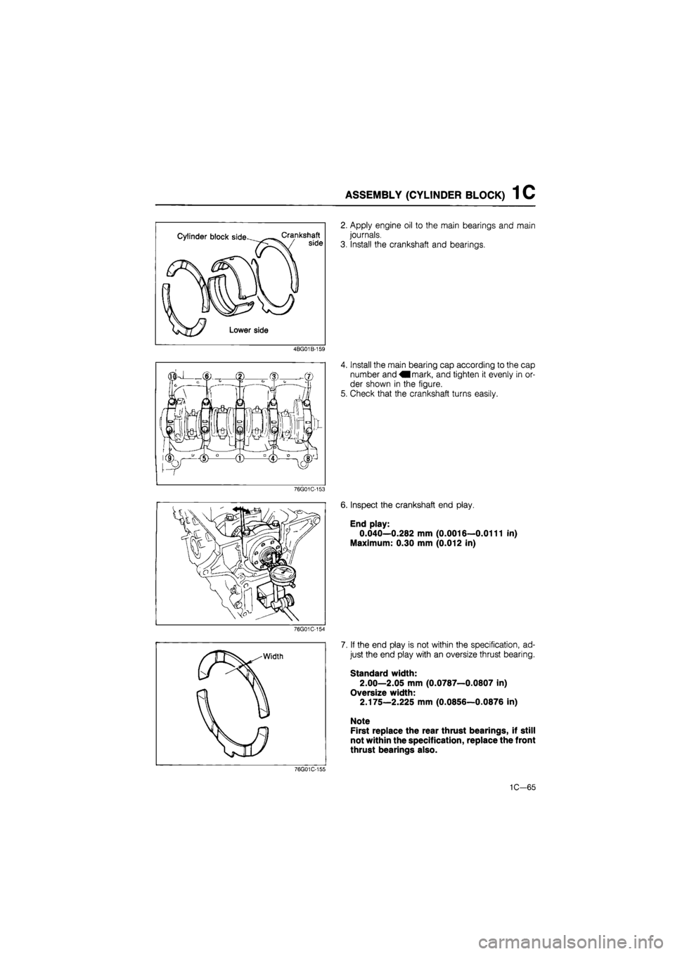
ASSEMBLY (CYLINDER BLOCK) 1 C
Cylinder block side Crankshaft side
Lower side
4BG01B-159
2. Apply engine oil to the main bearings and main
journals.
3. Install the crankshaft and bearings.
4. Install the main bearing cap according to the cap
number and mark, and tighten it evenly in or-
der shown in the figure.
5. Check that the crankshaft turns easily.
76G01C-153
6. Inspect the crankshaft end play.
End play:
0.040—0.282 mm (0.0016—0.0111 in)
Maximum: 0.30 mm (0.012 in)
76G01C-154
76G01C-155
7. If the end play is not within the specification, ad-
just the end play with an oversize thrust bearing.
Standard width:
2.00—2.05 mm (0.0787—0.0807 in)
Oversize width:
2.175—2.225 mm (0.0856—0.0876 in)
Note
First replace the rear thrust bearings, if still
not within the specification, replace the front
thrust bearings also.
1C-65
Page 278 of 1865
1C ASSEMBLY (CYLINDER BLOCK)
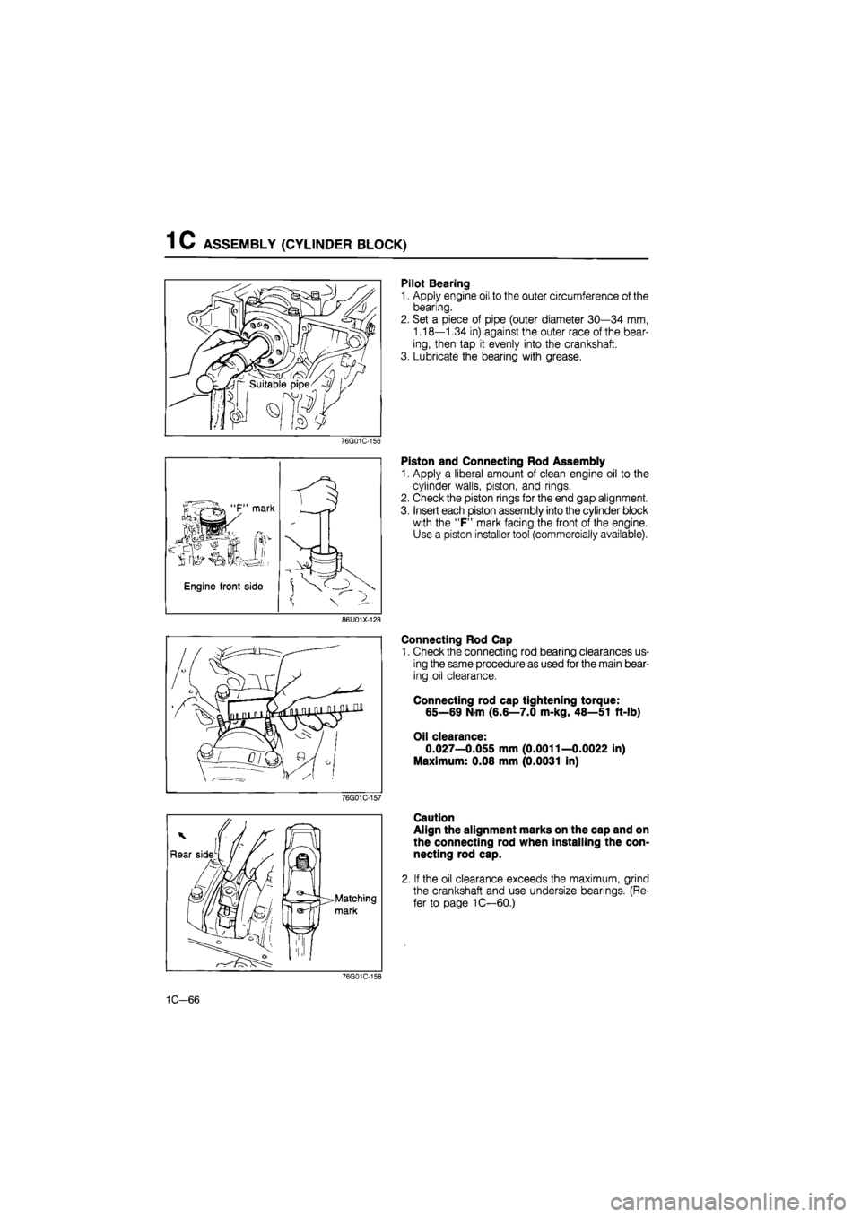
Pilot Bearing
1. Apply engine oil to the outer circumference of the
bearing.
2. Set a piece of pipe (outer diameter 30—34 mm,
1.18—1.34 in) against the outer race of the bear-
ing, then tap it evenly into the crankshaft.
3. Lubricate the bearing with grease.
76G01C-156
Piston and Connecting Rod Assembly
1. Apply a liberal amount of clean engine oil to the
cylinder walls, piston, and rings.
2. Check the piston rings for the end gap alignment.
3. Insert each piston assembly into the cylinder block
with the "F" mark facing the front of the engine.
Use a piston installer tool (commercially available).
86U01X-128
Connecting Rod Cap
1. Check the connecting rod bearing clearances us-
ing the same procedure as used for the main bear-
ing oil clearance.
Connecting rod cap tightening torque:
65—69 N-m (6.6—7.0 m-kg, 48—51 ft-lb)
Oil clearance:
0.027—0.055 mm (0.0011—0.0022 in)
Maximum: 0.08 mm (0.0031 in)
76G01C-157
Caution
Align the alignment marks on the cap and on
the connecting rod when installing the con-
necting rod cap.
If the oil clearance exceeds the maximum, grind
the crankshaft and use undersize bearings. (Re-
fer to page 1C—60.)
76G01C-158
1C-66