sensor MAZDA 626 1987 Manual PDF
[x] Cancel search | Manufacturer: MAZDA, Model Year: 1987, Model line: 626, Model: MAZDA 626 1987Pages: 1865, PDF Size: 94.35 MB
Page 636 of 1865

ESA CONTROL SYSTEM 4C
ELECTRONIC SPARK ADVANCE
(ESA)
CONTROL SYSTEM
Throttle sensor
76G04C-139
This system electronically controls the ignition timing to obtain better engine performance.
The best ignition timing is determined and set within the engine control unit based on signals from
the various sensors and switches.
The knock control function is used only with leaded fuel engines.
4C-75
Page 637 of 1865
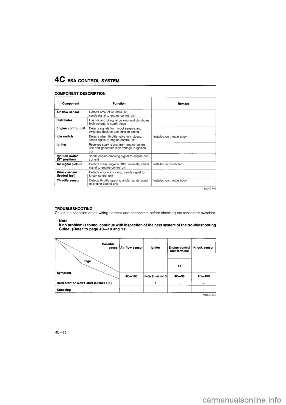
4C ESA CONTROL SYSTEM
COMPONENT DESCRIPTION
Component Function Remark
Air flow sensor Detects amount of intake air;
sends signal to engine control unit
Distributor Has Ne and G signal pick-up and distributes high voltage to spark plugs
Engine control unit Detects signals from input sensors and switches; decides best ignition timing
Idle switch Detects when throttle valve fully closed; sends signal to engine control unit Installed on throttle body
Igniter Receives spark signal from engine control unit and generates high voltage in ignition coil
Ignition switch
(ST position) Sends engine cranking signal to engine con-trol unit
Ne signal pick-up Detects crank angle at 180° intervals; sends signal to engine control unit Installed in distributor
Knock sensor (leaded fuel) Detects engine knocking; sends signal to knock control unit
Throttle sensor Detects throttle opening angle; sends signal to engine control unit Installed on throttle body
76G04C-140
TROUBLESHOOTING
Check the condition of the wiring harness and connectors before checking the sensors or switches.
Note
If no problem is found, continue with inspection of the next system of the troubleshooting
Guide. (Refer to page 4C—10 and 11)
Possible cause
Page
Symptom
Air flow sensor Igniter Engine control
unit terminal Knock sensor Possible cause
Page
Symptom
Air flow sensor Igniter
1X
Knock sensor Possible cause
Page
Symptom
4C—103 Refer to section 5 4C—98 4C—109
Hard start or won't start (Cranks OK) 3 1 2 —
Knocking — 1
76G04C-141
4C-76
Page 638 of 1865

EGR SYSTEM (UNLEADED FUEL) 4C
EXHAUST GAS RECIRCULATION
(EGR)
SYSTEM (UNLEADED FUEL)
This system introduces exhaust gas into the intake manifold to reduce NOx emissions. It operates de-
pending on the engine load, engine speed (1,500—3,500 rpm), engine coolant temperature (above
70°C, 158°F), and radiator coolant temperature (above 17°C, 63°F).
COMPONENT DESCRIPTION
Component Function Remark
EGR control valve Recirculates portion of exhaust gas
EGR modulator valve Controls vacuum acting on EGR control valve
Engine control unit Detects signals from input sensors and switches; con-trols solenoid valve (EGR)
Ne signal pick-up Detects crank angle at 180° intervals; sends signal to engine control unit
Solenoid valve (EGR) Controls vacuum to EGR control valve
Throttle sensor Detects throttle valve opening angle; sends signal to en-
gine control unit
Installed on throttle body
Water thermo sensor Detects coolant temperature; sends signal to engine control unit
Water thermo switch Detects radiator coolant temperature; sends signal to engine control unit ON: above 17°C (63°F)
76G04C-143
AC—17
Page 639 of 1865
4C EGR SYSTEM (UNLEADED FUEL)
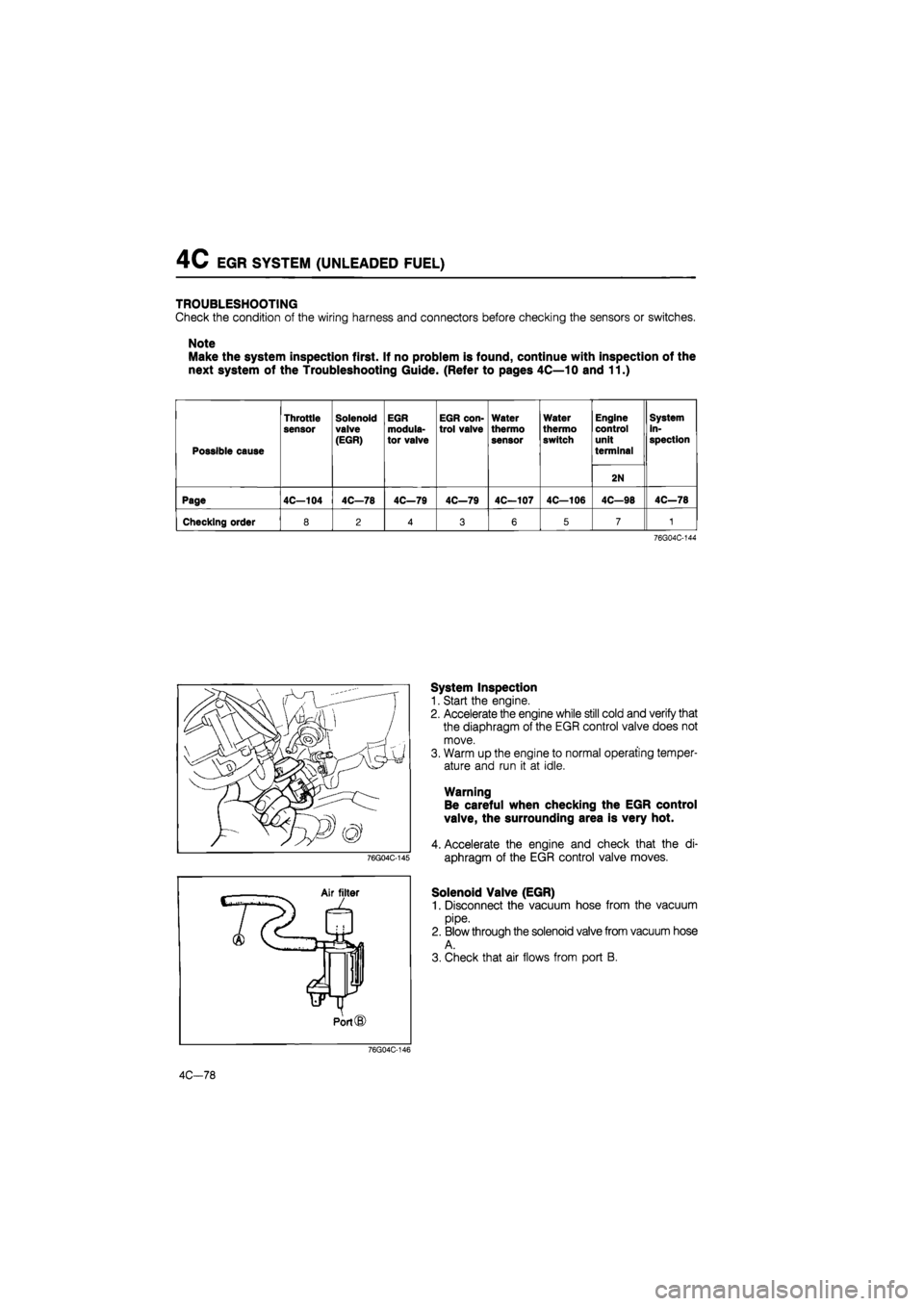
TROUBLESHOOTING
Check the condition of the wiring harness and connectors before checking the sensors or switches.
Note
Make the system inspection first. If no problem is found, continue with inspection of the
next system of the Troubleshooting Guide. (Refer to pages 4C—10 and 11.)
Possible cause
Throttle
sensor
Solenoid valve
(EGR)
EGR
modula-
tor valve
EGR con-trol valve
Water
thermo
sensor
Water
thermo switch
Engine control unit
terminal
System in-spection
2N
Page 4C—104 4C—78 4C—79 4C—79 4C—107 4C—106 4C—98 4C—78
Checking order 8 2 4 3 6 5 7 1
76G04C-144
System Inspection
1. Start the engine.
2. Accelerate the engine while still cold and verify that
the diaphragm of the EGR control valve does not
move.
3. Warm up the engine to normal operating temper-
ature and run it at idle.
Warning
Be careful when checking the EGR control
valve, the surrounding area is very hot.
4. Accelerate the engine and check that the di-
aphragm of the EGR control valve moves.
Solenoid Valve (EGR)
1. Disconnect the vacuum hose from the vacuum
pipe.
2. Blow through the solenoid valve from vacuum hose
A.
3. Check that air flows from port B.
76G04C-146
4C-78
Page 641 of 1865
4C EEC SYSTEM
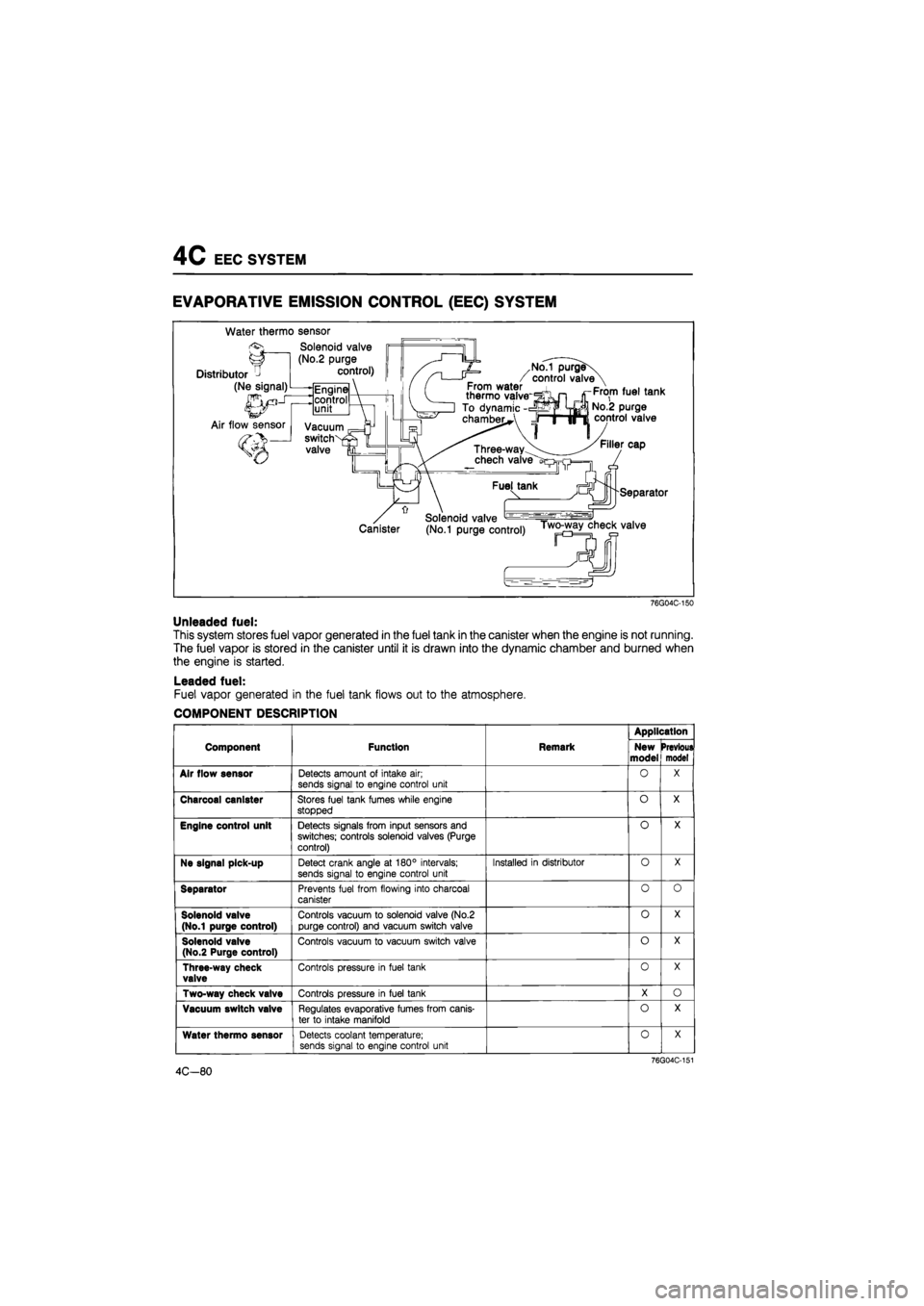
EVAPORATIVE EMISSION CONTROL
(EEC)
SYSTEM
Water thermo sensor
76G04C-150
Unleaded fuel:
This system stores fuel vapor generated in the fuel tank in the canister when the engine is not running.
The fuel vapor is stored in the canister until it is drawn into the dynamic chamber and burned when
the engine is started.
Leaded fuel:
Fuel vapor generated in the fuel tank flows out to the atmosphere.
COMPONENT DESCRIPTION
Application
Component Function Remark New
model Prevtoui model
Air flow sensor Detects amount of intake air; sends signal to engine control unit
O X
Charcoal canister Stores fuel tank fumes while engine stopped
o X
Engine control unit Detects signals from input sensors and
switches; controls solenoid valves (Purge
control)
o X
Ne signal pick-up Detect crank angle at 180° intervals; sends signal to engine control unit
Installed in distributor o X
Separator Prevents fuel from flowing into charcoal canister
o o
Solenoid valve
(No.1 purge control)
Controls vacuum to solenoid valve (No.2
purge control) and vacuum switch valve
0 X
Solenoid valve (No.2 Purge control)
Controls vacuum to vacuum switch valve o X
Three-way check valve Controls pressure in fuel tank o X
Two-way check valve Controls pressure in fuel tank X o
Vacuum switch valve Regulates evaporative fumes from canis-ter to intake manifold
o X
Water thermo sensor Detects coolant temperature; sends signal to engine control unit
0 X
76G04C-151
4C-80
Page 642 of 1865
EEC SYSTEM
4C
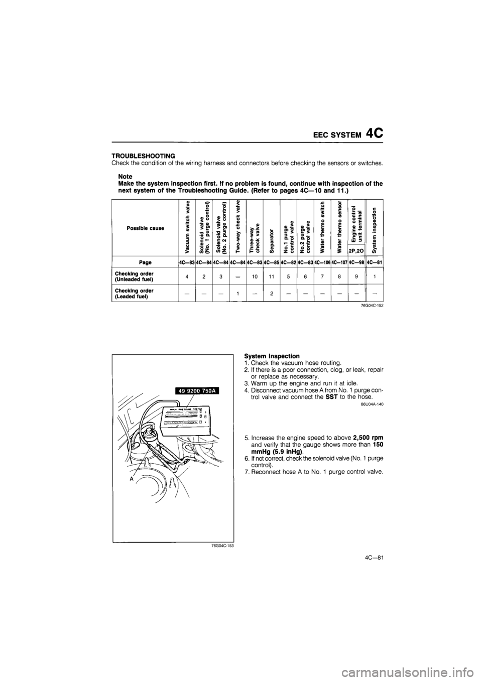
TROUBLESHOOTING
Check
the
condition
of the
wiring harness
and
connectors before checking
the
sensors
or
switches.
Note
Make
the
system inspection first.
If no
problem
is
found, continue with inspection
of the
next system
of the
Troubleshooting Guide. (Refer
to
pages 4C—10
and 11.)
Possible cause
« > (0 >
£ O
S in
E 3 3
Solenoid
valve
(No.
1 purge
control)
Solenoid
valve
(No.
2 purge
control)
Two-way
check
valve
a>
>. >
i
S
i
^
3>
o
o CO k n
V
*
£
3
_
a
o
k. T-
a>
E»S 3
_
a
o
CM
£
£ O
S in o E tm a> £
w V
o ID C a> in o E k a> £ **
a>
Engine
control
unit
terminal
c o +s o a> a. w c
E a> O <0 >
Solenoid
valve
(No.
1 purge
control)
Solenoid
valve
(No.
2 purge
control)
Two-way
check
valve
>-
0)
£
£
1-
o
Q. d) o
fe
Z
o
ofe Z
O
(0 (0 $ 2P,20
in
(O
Page 4C—83 4C-84 4C-84 4C—84 4C-83 4C-85 4C-82 4C-83 4C-106 4C-107 4C—98 4C-81
Checking order (Unleaded fuel) 4 2 3 — 10 11 5 6 7 8 9 1
Checking order
(Leaded fuel) — — — 1 — 2
76G04C-152
System Inspection
1. Check
the
vacuum hose routing.
2. If there
is a
poor connection, clog,
or
leak, repair
or replace
as
necessary.
3. Warm
up the
engine
and run it at
idle.
4. Disconnect vacuum hose
A
from
No. 1
purge con-
trol valve
and
connect
the SST to the
hose.
86U04A-140
5. Increase
the
engine speed
to
above 2,500
rpm
and verify that
the
gauge shows more than
150
mmHg
(5.9
inHg).
6. If not correct, check the solenoid valve (No.
1
purge
control).
7. Reconnect hose
A to No. 1
purge control valve.
4C-81
76G04C-153
Page 652 of 1865

CONTROL SYSTEM 4C
CONTROL SYSTEM
Throttle sensor
Solenoid Solenoid Idle valve valve switch (VIC) (PRC)
Solenoid
valve
control)*
Solenoid valve
'(No.1 purge control)*1
E/L control unit
Engine control unit
Control relay
Injector
Knock sensor* -
Water thermo
switch*1
"1...Unleaded fuel
*2...Leaded fuel
Oxygen Distributor Water thermo sensor*1 sensor
Clutch switch
Oxygen sensor
relay*1
Solenoid valve
(EGR)*1
/ Solenoid valve 7 (ISC)
Air flow sensor
Neutral switch
76G04C-166
The control system consists of the input devices and the engine control unit. The control unit controls
the fuel injection amount (EGI), fuel injection pressure, bypass air amount, ignition timing, switch moni-
tor function, and fail-safe function.
4C-91
Page 653 of 1865

4C CONTROL SYSTEM
RELATIONSHIP CHART
Output Devices
and
Input Devices (Unleaded fuel)
IGNITION SWITCH
(ON POSION) X X X X X O X X X X X X X X O
TEST CONNECTOR X X X O X X X X X X X X X O X
ELECTRICAL LOAD CONTROL UNIT X X X o X X X X X X X X X X X
P/S PRESSURE SWITCH X X X o X X X X X X X X X X X
A/C SWITCH X X X o X X X X X X X X O X X
IGNITION SWITCH
(STA POSITION) O O X o O X X X X O X X X O X
NEUTRAL
AND
CLUTCH SWITCH O X X o X X X X X X X X X X X
OXYGEN SENSOR o X X X X X X X X X X X X X X
WATER THERMO
SWITCH (RADIATOR) o X X X X X X X o X X X X X X
INTAKE
AIR
THERMO SENSOR X X X X X X X X X O X X X X X
WATER
THERMO SENSOR o X X o X X o o O O X X X O o
IDLE SWITCH o X X o X X X X X o X X X O X
THROTTLE SENSOR o X X X X X X X O X X X X o X
AIR FLOW SENSOR o X X X X X X o X X X X X o O
Ne SIGNAL o o X O o X X O O O o o X o O
G SIGNAL X O X X X X X X X X X X X X X
\
INPUT
DEVICE
OUTPUT
DEVICE
FUEL
INJECTION
AMOUNT FUEL
INJECTION
TIMING
AIR
VALVE
ISC
VALVE
FUEL
PUMP
CONTROL
MAIN
POWER
CONTROL
SOLENOID
VALVE
(No.1
PURGE)
SOLENOID
VALVE
(No.2
PURGE)
SOLENOID
VALVE
(EGR)
SOLENOID
VALVE
(PRESSURE
REGULATOR
CONTROL)
SOLENOID
VALVE
(VARIABLE
INERTIA
CONTROL)
OXYGEN
SENSOR
RELAY
I A/C
RELAY
IGNITER
AIR
FLOW
SENSOR
(BURN-OFF)
\
INPUT
DEVICE
OUTPUT
DEVICE
INJECTOR
BAC
VALVE
CONTROL
RELAY
SOLENOID
VALVE
(No.1
PURGE)
SOLENOID
VALVE
(No.2
PURGE)
SOLENOID
VALVE
(EGR)
SOLENOID
VALVE
(PRESSURE
REGULATOR
CONTROL)
SOLENOID
VALVE
(VARIABLE
INERTIA
CONTROL)
OXYGEN
SENSOR
RELAY
I A/C
RELAY
IGNITER
AIR
FLOW
SENSOR
(BURN-OFF)
76G04C-167
4C—92
Page 654 of 1865

CONTROL SYSTEM 4C
Output Devices and In put Devices (Leaded fuel)
IGNITION SWITCH
(ON POSITION) X X X X X O X X X X O
TEST CONNECTOR X X X O X X X X X O X
KNOCK SENSOR X X X X X X X X X o X
ELECTRICAL LOAD
CONTROL UNIT X X X O X X X X X X X
P/S PRESSURE SWITCH X X X o X X X X X X X
A/C SWITCH X X X o X X X X O X X
IGNITION SWITCH (STA POSITION) O O X o O X O X X O X
NEUTRAL AND
CLUTCH SWITCH O X X o X X X X X X X
INTAKE AIR THERMO SENSOR X X X X X X O X X X X
WATER THERMO SENSOR O X X o X X O X X O o
IDLE SWITCH o X X o X X o X X O X
VARIABLE RESISTOR (IN AIR FLOW SENSOR) o X X X X X X X X X X
AIR FLOW SENSOR o X X X X X X X X O O
Ne SIGNAL o o X O o X O o X o O
G SIGNAL X O X X X X X X X X X
INPUT
DEVICE
OUTPUT
DEVICE
FUEL
INJECTION
AMOUNT
FUEL
INJECTION
TIMING
AIR
VALVE
ISC
VALVE
FUEL
PUMP
CONTROL
MAIN
POWER
CONTROL
SOLENOID
VALVE
(PRESSURE
REGULATOR
CONTROL)
SOLENOID
VALVE
(VARIABLE
INERTIA
CONTROL)
A/C
RELAY
IGNITER
AIR
FLOW
SENSOR
(BURN-OFF)
INPUT
DEVICE
OUTPUT
DEVICE
INJECTOR
BAC
VALVE
CONTROL
RELAY
SOLENOID
VALVE
(PRESSURE
REGULATOR
CONTROL)
SOLENOID
VALVE
(VARIABLE
INERTIA
CONTROL)
A/C
RELAY
IGNITER
AIR
FLOW
SENSOR
(BURN-OFF)
76G04C-168
4C—93
Page 661 of 1865
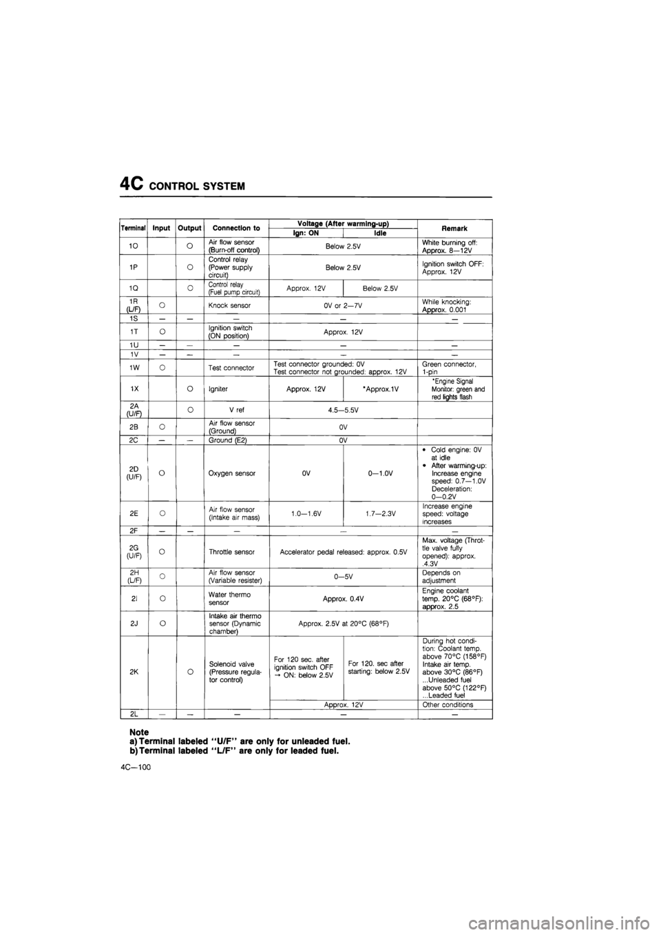
4C CONTROL SYSTEM
Terminal Input Output Connection to Voltage (After warming-up) Remark Terminal Input Output Connection to Ign: ON Idle Remark
10 o Air flow sensor
(Burn-off control) Below 2.5V White burning off:
Approx. 8—12V
1P o
Control relay (Power supply circuit) Below 2.5V Ignition switch OFF:
Approx. 12V
1Q 0 Control relay (Fuel pump circuit) Approx. 12V Below 2.5V
1R
(L/F) O Knock sensor OV or 2—7V While knocking:
Approx. 0.001
1S — — — — —
1T o Ignition switch
(ON position) Approx. 12V
1U — — — — —
1V — — — — —
1W o Test connector Test connector grounded: OV Test connector not grounded: approx. 12V Green connector, 1-pin
1X o Igniter Approx. 12V *Approx.1V 'Engine Signal
Monitor: green and
red lights flash
2A (U/F) o V ref 4.5—5.5V
2B o Air flow sensor
(Ground) OV
2C — — Ground (E2) OV
2D (U/F) o Oxygen sensor OV 0-1.0V
• Cold engine: 0V at idle
• After warming-up: Increase engine speed: 0.7—1.0V Deceleration: 0—0.2V
2E o Air flow sensor
(Intake air mass) 1.0—1.6V 1.7—2.3V Increase engine speed: voltage increases
2F — — — .— —
2G (U/F) o Throttle sensor Accelerator pedal released: approx. 0.5V
Max. voltage (Throt-tle valve fully opened): approx. ,4.3V
2H (L/F) o Air flow sensor (Variable resister) 0-5V Depends on
adjustment
21 o Water thermo sensor Approx. 0.4V
Engine coolant
temp. 20°C (68°F):
approx. 2.5
2J o Intake air thermo sensor (Dynamic chamber)
Approx. 2.5V at 20°C (68°F)
2K o
Solenoid valve (Pressure regula-tor control)
For 120 sec. after ignition switch OFF - ON: below 2.5V
For 120. sec after starting: below 2.5V
During hot condi-tion: Coolant temp, above 70°C (158°F) Intake air temp, above 30°C (86°F) ...Unleaded fuel above 50°C (122°F) ...Leaded fuel
2K o
Solenoid valve (Pressure regula-tor control)
ADDrox. 12V Other conditions
2L — — — — —
Note
a) Terminal labeled "U/F" are only for unleaded fuel.
b)Terminal labeled "L/F" are only for leaded fuel.
4C-100