sensor MAZDA 626 1987 Manual Online
[x] Cancel search | Manufacturer: MAZDA, Model Year: 1987, Model line: 626, Model: MAZDA 626 1987Pages: 1865, PDF Size: 94.35 MB
Page 662 of 1865
CONTROL SYSTEM 4C
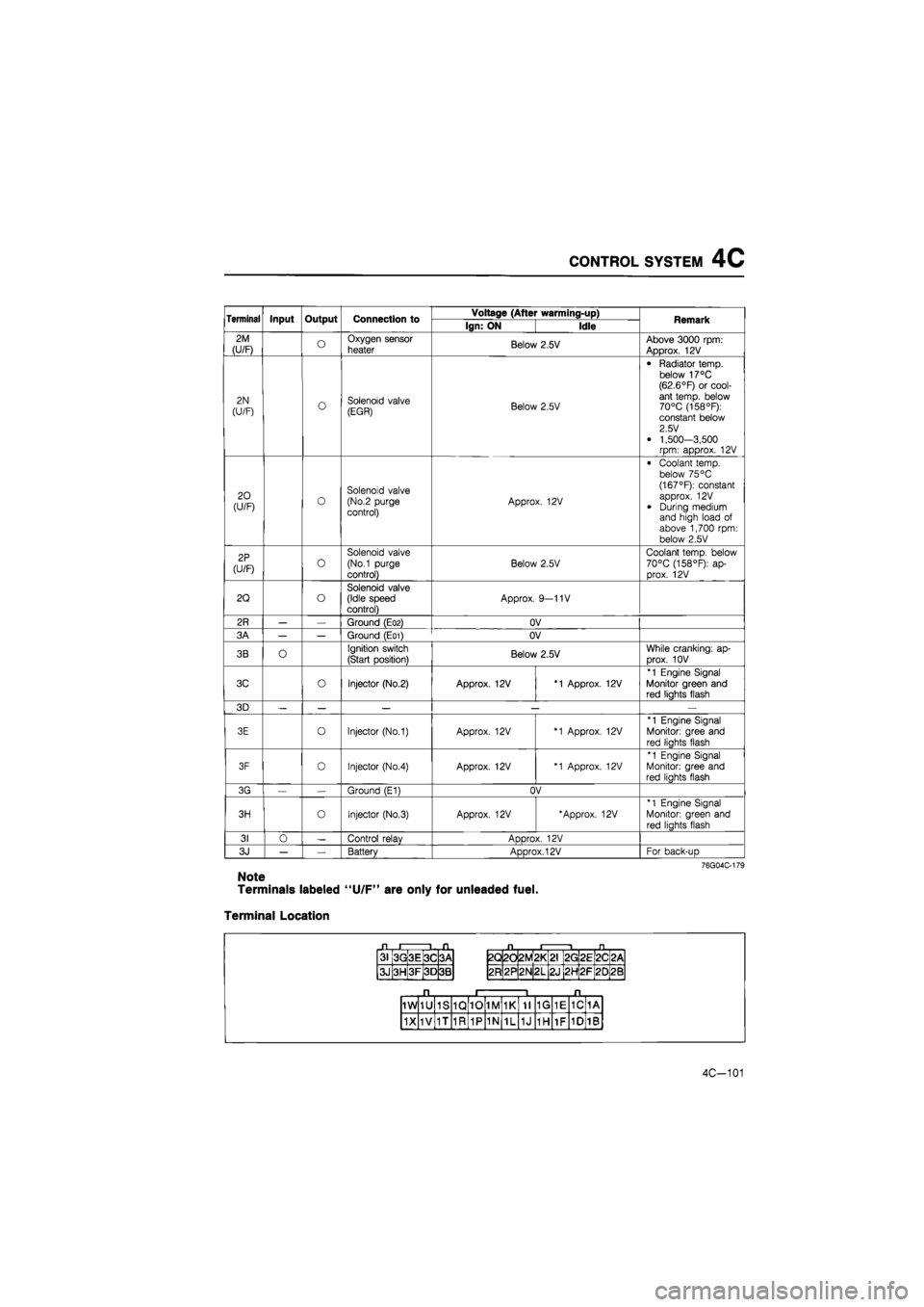
Terminal Input Output Connection to Voltage (After warming-up) Remark Terminal Input Output Connection to Ign: ON Idle Remark
2M
(U/F) o Oxygen sensor
heater Below 2.5V Above 3000 rpm: Approx. 12V
2N
(U/F) o Solenoid valve (EGR) Below 2.5V
• Radiator temp, below 17°C (62.6°F) or cool-ant temp, below 70°C (158°F): constant below 2.5 V
• 1,500-3,500 rpm: approx. 12V
20 (U/F) 0 Solenoid valve (No.2 purge control) Approx. 12V
• Coolant temp, below 75 °C (167°F): constant approx. 12V
• During medium and high load of above 1,700 rpm: below 2.5V
2P
(U/F) o
Solenoid valve
(No.1 purge
control)
Below 2.5V
Coolant temp, below 70°C (158°F): ap-prox. 12V
2Q o Solenoid valve (Idle speed control) Approx. 9—11V
2R — — Ground (E02) OV
3A — — Ground (E01) OV
3B O Ignition switch
(Start position) Below 2.5V While cranking: ap-
Drox. 10V
3C o Injector (No.2) Approx. 12V *1 Approx. 12V
*1 Engine Signal Monitor green and red liahts flash
3D — — — — —
3E o Injector (No.1) Approx. 12V *1 Approx. 12V
*1 Engine Signal
Monitor: gree and
red liahts flash
3F 0 Injector (No.4) Approx. 12V *1 Approx. 12V
*1 Engine Signal Monitor: gree and red liahts flash
3G — Ground (E1) OV
3H o Injector (No.3) Approx. 12V 'Approx. 12V *1 Engine Signal
Monitor: green and
red lights flash
31 0 — Control relav ADDrox. 12V
3J — — Battery Approx. 12V For back-uD
76G04C-179
Note
Terminals labeled "U/F" are only for unleaded fuel.
Terminal Location
31 3G 3E 3C 3A
3J 3H 3F 3D 3B
2Q 2d 2M *
L
2G 2E 2C <
CM
2R 2P 2N 2L 2J 2H 2F 20 2B
1W 1U 1S 1Q 10 1M 1K 11 1G 1E 1C 1A
1X 1V 1T 1R 1P 1N 1L 1J 1H 1F 1D 1B
4C-101
Page 664 of 1865
CONTROL SYSTEM 4C
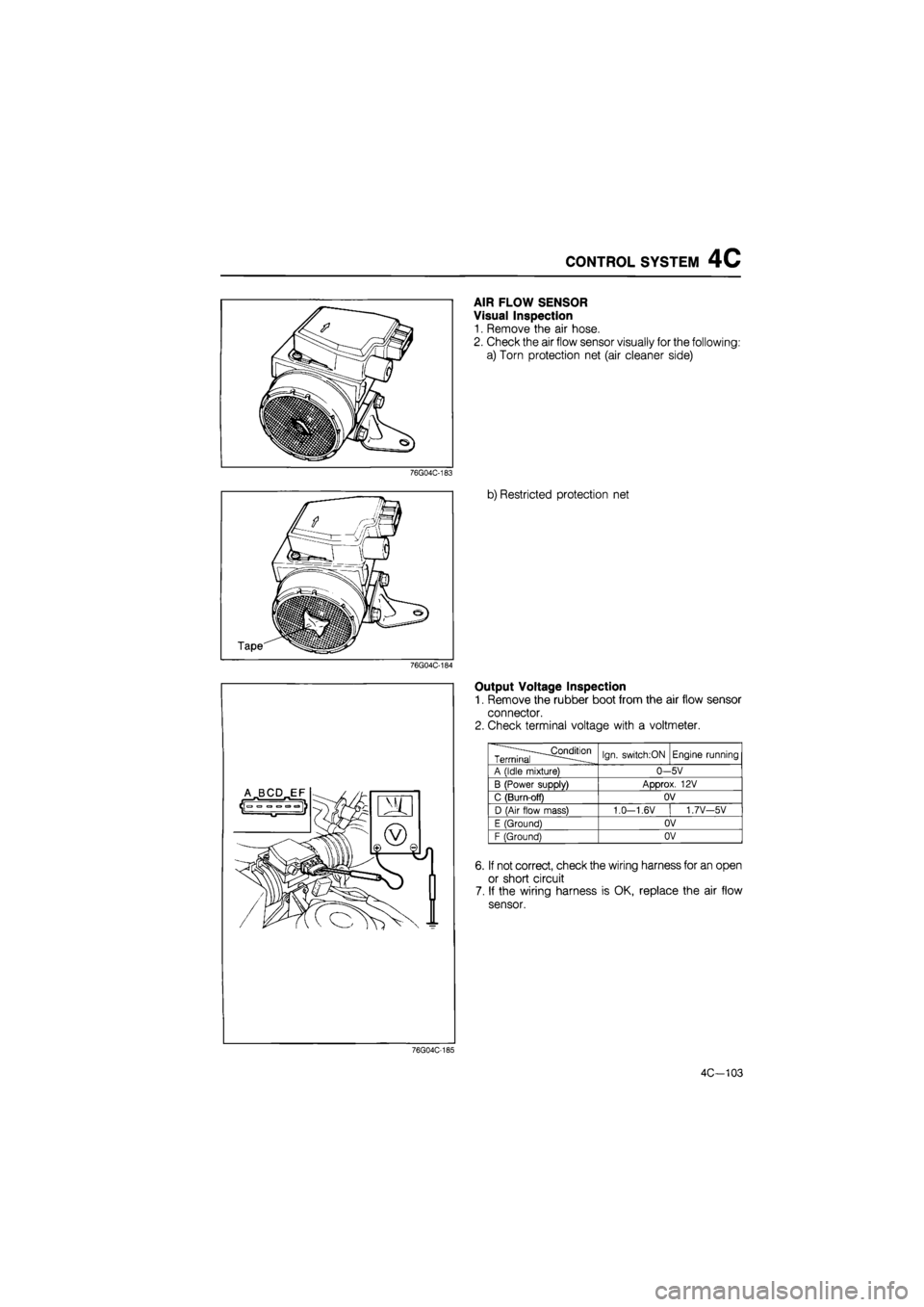
AIR FLOW SENSOR
Visual Inspection
1. Remove the air hose.
2. Check the air flow sensor visually for the following:
a) Torn protection net (air cleaner side)
76G04C-183
b) Restricted protection net
76G04C-184
Output Voltage Inspection
1. Remove the rubber boot from the air flow sensor
connector.
2. Check terminal voltage with a voltmeter.
——^.Condition Terminal — ... Ign. switch;ON Engine running
A (Idle mixture) 0—5V
B (Power supply) Approx. 12V
C (Burn-off) OV
D (Air flow mass) 1.0-1,6V I 1.7V-5V
E (Ground) OV
F (Ground) 0V
6. If not correct, check the wiring harness for an open
or short circuit
7. If the wiring harness is OK, replace the air flow
sensor.
76G04C-185
4C-103
Page 665 of 1865
4C CONTROL SYSTEM
Jjf (Terminal A)
n PI
WRED r^j
BLACK
BLACK 1 (Terminal C)
76G04C-189
Replacement
1. Disconnect the connector.
2. Loosen the air hose clamps.
3. Replace the air flow sensor.
Caution
Install the air flow sensor so that the arrow on
the sensor aligns with air flow direction.
4. Tighten the hose clamps.
5. Reconnect the connector to the sensor.
THROTTLE SENSOR
Caution
Use a precision voltmeter with a scale of 0.01V
to inspect or adjust the throttle sensor. If it
is not available, replace the throttle sensor
and throttle body as an assembly.
Inspection
1. Disconnect the throttle sensor connector (3-pin).
2. Connect the SST between the throttle sensor and
the wiring harness.
3. Turn the ignition switch ON.
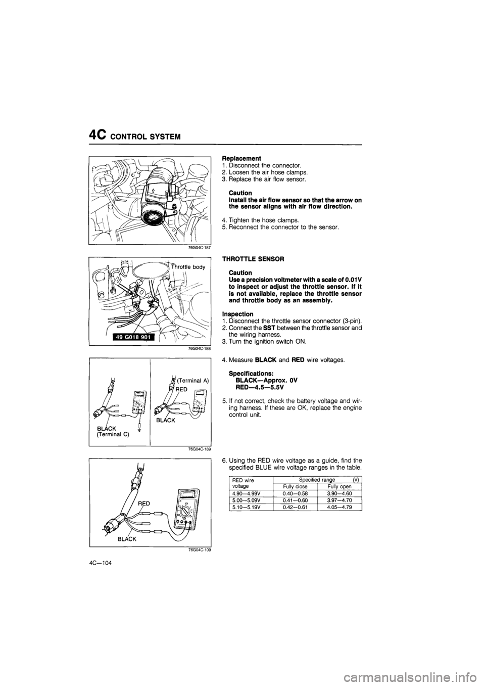
4. Measure BLACK and RED wire voltages.
Specifications:
BLACK—Approx. OV
RED—4.5—5.5V
5. If not correct, check the battery voltage and wir-
ing harness. If these are OK, replace the engine
control unit.
6. Using the RED wire voltage as a guide, find the
specified BLUE wire voltage ranges in the table.
RED wire voltage
Specified range (V) RED wire voltage Fully close Fully open
4.90—4.99V 0.40-0.58 3.90-4.60
5.00—5.09V 0.41—0.60 3.97-4.70
5.10-5.19V 0.42—0.61 4.05—4.79
4C-104
Page 666 of 1865
CONTROL SYSTEM 4C
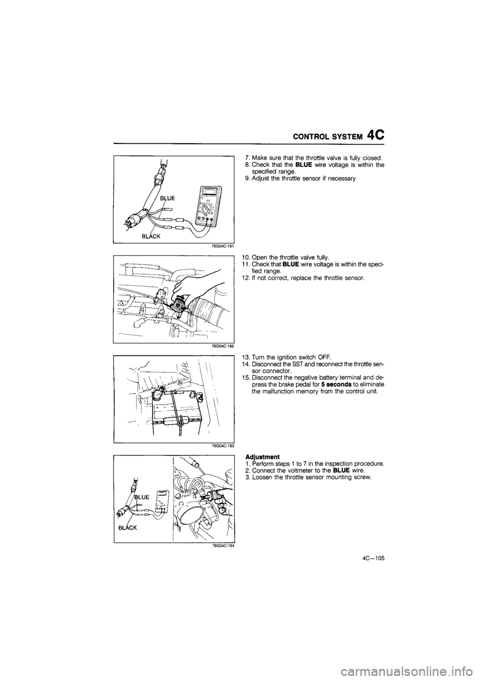
7. Make sure that the throttle valve is fully closed.
8. Check that the BLUE wire voltage is within the
specified range.
9. Adjust the throttle sensor if necessary
76g04c-191
10. Open the throttle valve fully.
11. Check that BLUE wire voltage is within the speci-
fied range.
12. If not correct, replace the throttle sensor.
76g04c-192
13. Turn the ignition switch OFF.
14. Disconnect the SST and reconnect the throttle sen-
sor connector.
15. Disconnect the negative battery terminal and de-
press the brake pedal for 5 seconds to eliminate
the malfunction memory from the control unit.
76g04c-193
Adjustment
1. Perform steps 1 to 7 in the inspection procedure.
2. Connect the voltmeter to the BLUE wire.
3. Loosen the throttle sensor mounting screw.
76G04C-194
4C-105
Page 667 of 1865
4C CONTROL SYSTEM
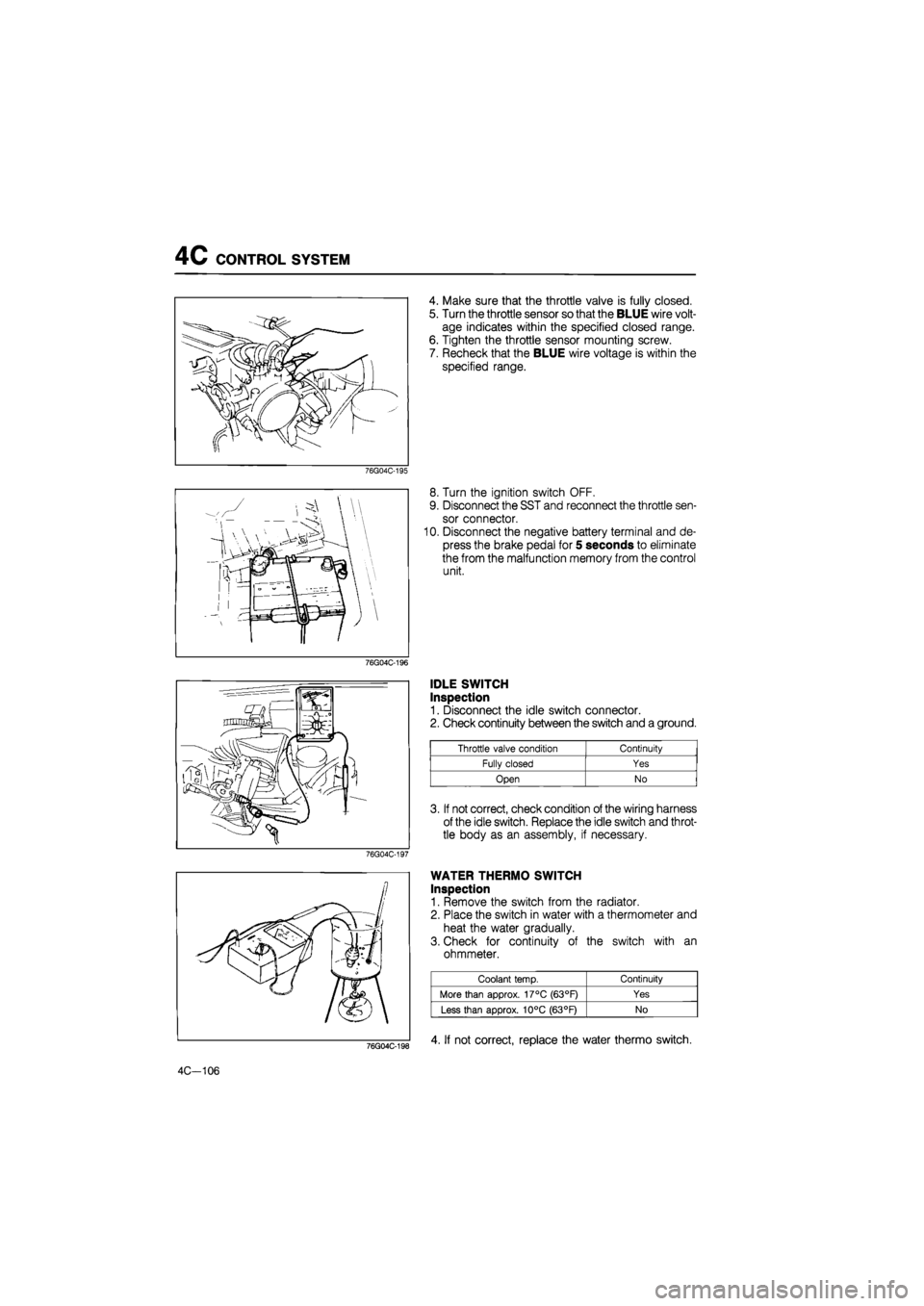
4. Make sure that the throttle valve is fully closed.
5. Turn the throttle sensor so that the BLUE wire volt-
age indicates within the specified closed range.
6. Tighten the throttle sensor mounting screw.
7. Recheck that the BLUE wire voltage is within the
specified range.
76G04C-195
8. Turn the ignition switch OFF.
9. Disconnect the SST and reconnect the throttle sen-
sor connector.
10. Disconnect the negative battery terminal and de-
press the brake pedal for 5 seconds to eliminate
the from the malfunction memory from the control
unit.
76G04C-196
76G04C-198
4C-106
IDLE SWITCH
Inspection
1. Disconnect the idle switch connector.
2. Check continuity between the switch and a ground.
Throttle valve condition Continuity
Fully closed Yes
Open No
3. If not correct, check condition of the wiring harness
of the idle switch. Replace the idle switch and throt-
tle body as an assembly, if necessary.
WATER THERMO SWITCH
Inspection
1. Remove the switch from the radiator.
2. Place the switch in water with a thermometer and
heat the water gradually.
3. Check for continuity of the switch with an
ohmmeter.
Coolant temp. Continuity
More than approx. 17°C (63°F) Yes
Less than approx. 10°C (63°F) No
4. If not correct, replace the water thermo switch.
Page 668 of 1865
CONTROL SYSTEM 4C
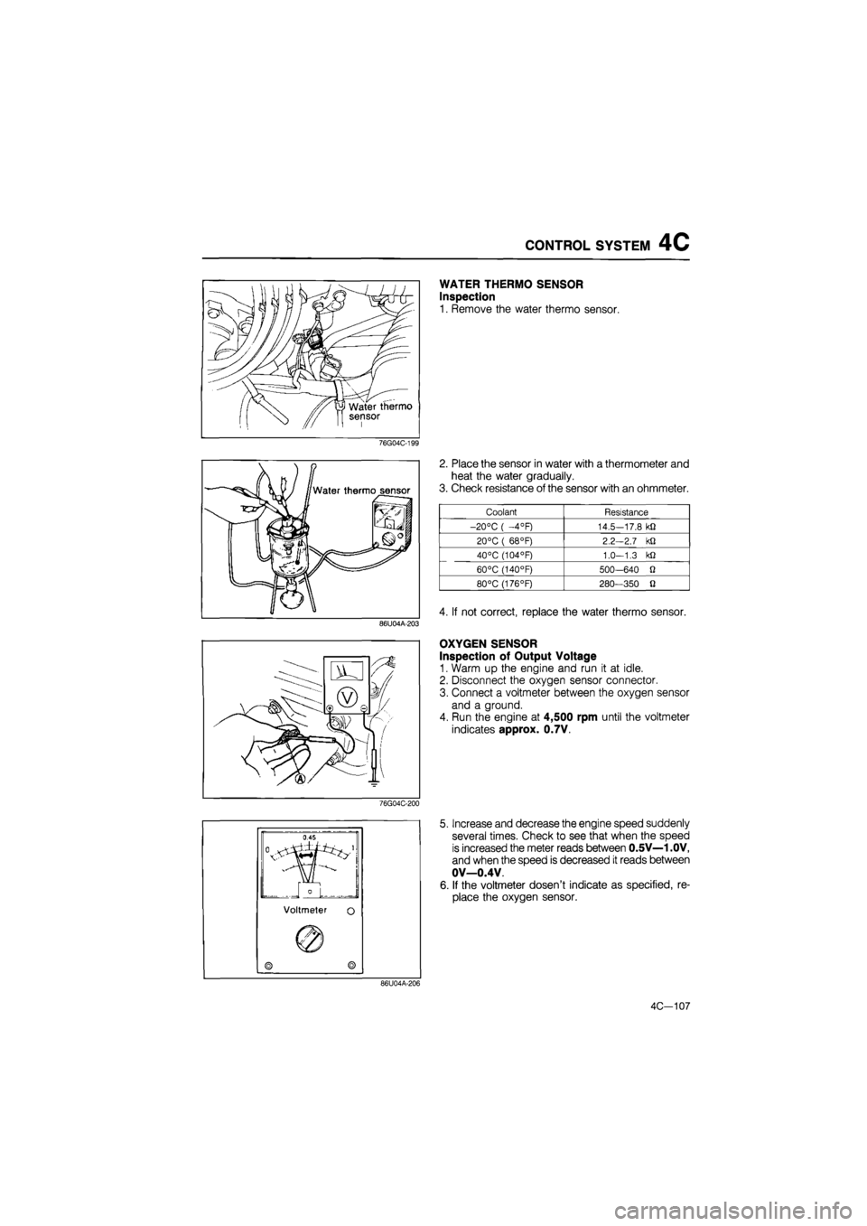
WATER THERMO SENSOR
Inspection
1. Remove the water thermo sensor.
76G04C-199
86U04A-203
2. Place the sensor in water with a thermometer and
heat the water gradually.
3. Check resistance of the sensor with an ohmmeter.
Coolant Resistance
-20°C ( —4°F) 14.5—17.8 kfl
20°C ( 68°F) 2.2-2.7 kQ
40°C (104°F) 1.0—1.3 kQ
60°C (140°F) 500—640 O
80°C (176°F) 280—350 fl
4. If not correct, replace the water thermo sensor.
OXYGEN SENSOR
Inspection of Output Voltage
1. Warm up the engine and run it at idle.
2. Disconnect the oxygen sensor connector.
3. Connect a voltmeter between the oxygen sensor
and a ground.
4. Run the engine at 4,500 rpm until the voltmeter
indicates approx. 0.7V.
76G04C-200
5. Increase and decrease the engine speed suddenly
several times. Check to see that when the speed
is increased the meter reads between 0.5V—1 .OV,
and when the speed is decreased it reads between
OV—0.4V.
6. If the voltmeter dosen't indicate as specified, re-
place the oxygen sensor.
86U04A-206
4C—107
Page 670 of 1865
CONTROL SYSTEM 4C
76G04C-203
76G04C-204
76G04C-205
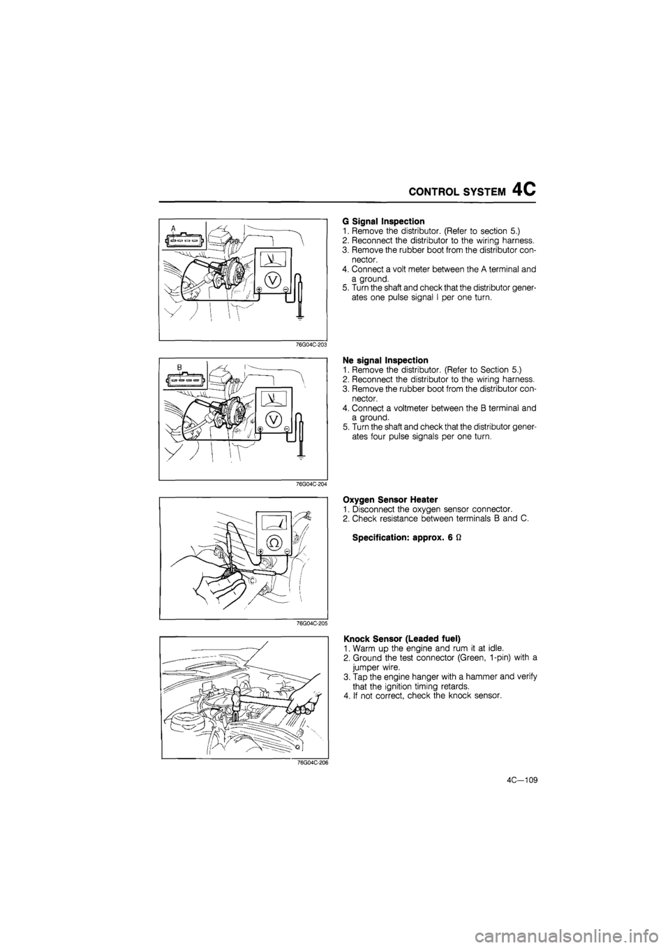
G Signal Inspection
1. Remove the distributor. (Refer to section 5.)
2. Reconnect the distributor to the wiring harness.
3. Remove the rubber boot from the distributor con-
nector.
4. Connect a volt meter between the A terminal and
a ground.
5. Turn the shaft and check that the distributor gener-
ates one pulse signal I per one turn.
Ne signal Inspection
1. Remove the distributor. (Refer to Section 5.)
2. Reconnect the distributor to the wiring harness.
3. Remove the rubber boot from the distributor con-
nector.
4. Connect a voltmeter between the B terminal and
a ground.
5. Turn the shaft and check that the distributor gener-
ates four pulse signals per one turn.
Oxygen Sensor Heater
1. Disconnect the oxygen sensor connector.
2. Check resistance between terminals B and C.
Specification: approx. 6 Q
Knock Sensor (Leaded fuel)
1. Warm up the engine and rum it at idle.
2. Ground the test connector (Green, 1-pin) with a
jumper wire.
3. Tap the engine hanger with a hammer and verify
that the ignition timing retards.
4. If not correct, check the knock sensor.
76G04C-206
4C-109
Page 671 of 1865

4C CONTROL SYSTEM
76G04C-207
76G04C-208
Replacement
1. Disconnect the knock sensor connector.
2. Lift the vehicle and remove the intake manifold
bracket.
3. Remove the knock sensor with the SST.
4. Install the knock sensor in the reverse order of
removal.
INTAKE AIR THERMO SENSOR (DYNAMIC
CHAMBER)
Inspection
1. Disconnect the intake air thermo sensor connector.
2. Connect an ohmmeter to the sensor terminals.
3. Check the resistance of the sensor.
Temperature Resistance (kQ)
20°C (68°F) 29.7—36.3
50°C (122°F) 8.4-10.2
85 °C (185°F) 2.5-3.1
4. Reconnect the sensor connector.
Replacement
1. Disconnect the intake air thermo sensor connector.
2. Remove the sensor.
3. Install the sensor.
Note
When installing the sensor, tighten to the
specified torque.
Specified torque:
6.9—8.8 N-m (0.7—0.9 m-kg, 72 in-lb)
76G04C-209
4C—110
Page 672 of 1865

4D
FUEL AND EMISSION
CONTROL SYSTEM
(DIESEL)
OUTLINE 4D— 2
SPECIFICATIONS 4D— 2
TROUBLESHOOTING GUIDE 4D— 3
ON-VEHICLE MAINTENANCE 4D— 4
AIR CLEANER ELEMENT 4D— 4
WATER DRAINING 4D— 4
AIR BLEEDING 4D— 4
INJECTION TIMING 4D— 5
IDLE SPEED 4D— 6
EXHAUST SMOKE 4D— 6
INTAKE AIR SYSTEM 4D— 7
STRUCTURAL VIEW 4D— 7
AIR DUCT AND AIR CLEANER 4D— 8
INTAKE MANIFOLD 4D— 9
SUPERCHARGING SYSTEM (RF-CX) 4D-10
TROUBLESHOOTING GUIDE 4D—10
ON-VEHICLE INSPECTION 4D—11
COMPREX SUPERCHARGER 4D—13
STARTING VALVE 4D—15
INTERCOOLER 4D—16
BOOST AIR TEMPERATURE SENSOR 4D—17
EXHAUST SYSTEM 4D—18
STRUCTURAL VIEW 4D—18
EXHAUST MANIFOLD 4D—19
EXHAUST PIPE AND MAIN SILENCER .... 4D—20
FUEL SYSTEM 4D—21
STRUCTURAL VIEW 4D—21
FUEL FILTER 4D—22
SEDIMENTER (GENERAL) 4D—22
WATER LEVEL SENSOR 4D—23
INJECTION PUMP 4D—24
INJECTION NOZZLE 4D—31
FUEL TANK 4D—34
76G04D-001
Page 688 of 1865

4D SUPERCHARGING SYSTEM (RF-CX)
BOOST AIR TEMPERATURE SENSOR
Removal
Remove the boost air temperature sensor from the
compressed air funnel.
76G04D-039
Thermometer
Inspection
1. Place the boost air temperature sensor in oil.
2. Heat the oil and check continuity of the sensor with
an ohmmeter. Replace if necessary.
Continuity : over 150°C (302°F)
No continuity: below 143°C (289°F)
76G04D-040
Installation
Install the boost air temperature sensor in the com-
pressed air funnel.
Tightening torque:
29—39 N m (3.0—4.0 m-kg, 22—29 ft-lb)
76G04D-041
4D—17