ignition MAZDA MX-5 1994 Owners Manual
[x] Cancel search | Manufacturer: MAZDA, Model Year: 1994, Model line: MX-5, Model: MAZDA MX-5 1994Pages: 1708, PDF Size: 82.34 MB
Page 263 of 1708

F FUEL SYSTEM FUEL PUMP Inspection Fuel pump operation 1. Connect the data link connector terminals F/P and GND , with a jumper wire. 2. Remove the fuel filler cap. 3. Turn the ignition switch ON. 4. Listen for operational sound of the fuel pump at the filler inlet. 5. Install the fuel filler cap. 6. If no sound was heard, measure the voltage between the fuel pump connector wire to ground. Voltage: Battery positive voltage 7. If not correct, check the fuel pump relay and its circuits. (Refer to page F-116.) 8. If the voltage is normal, check for continuity between fuel pump connector (6) and a ground. 9. If there is continuity, replace the fuel pump. 10. If no continuity, repair the ground circuit. Hold pressure Perform this inspection if the fuel pressure hold inspec- tion is not as specified. (Refer to page F-109.) Warning Fuel line spills and leaks can be dangerous. Fuel can ignite and cause serious injuries or death and can damage the vehicle. Fuel can also irritate skin and eyes. To prevent this from happening, release the fuel pressure according to "Fuel Line Safety Procedures" on page F-108. 1. Disconnect the negative battery terminal. 2. Connect a fuel pressure gauge to the fuel main pipe and plug the outlet of the fuel pressure gauge as shown. (Install clamps as shown.) 3. Connect the negative battery terminal. Gartner Banana
Page 264 of 1708

FUEL SYSTEM 4. Connect data link connector terminals FIP and GND with a jumper wire. 5. Turn the ignition switch ON for 10 sec. to operate the fuel pump. 6. Turn the ignition switch OFF and disconnect the jumper wire. 7. Observe the fuel pressure after 5 min. Fuel pressure: More than 343 kPa (3.5 kgf/cm2, 50 psi) 8. If not as specified, replace the fuel pump. Fuel pump maximum pressure Warning Fuel line spills and leaks can be dangerous. Fuel can ignite and cause serious injuries or death and can damage the vehicle. Fuel can also irritate skin and eyes. To prevent this from happening, release the fuel pressure according to "Fuel Line Safety Procedures" on page F-108. 1. Disconnect the negative battery terminal. 2. Connect a fuel pressure gauge to the fuel main pipe and plug the outlet of the fuel pressure gauge as shown. (Install clamps as shown.) 3. Connect the negative battery terminal. 4. Connect data link connector terminals FIP and GND with a jumper wire. 5. Turn the ignition switch ON to operate the fuel pump. 6. Measure the pump maximum pressure. Fuel pump maximum pressure: 480-657 kPa (4.9-6.7 kgf/cm2, 69-95 psi) 7. Turn the ignition switch OFF and disconnect the jumper wire. 8. If not as specified, replace the fuel pump. Replacement Warning Fuel line spills and leaks can be dangerous. Fuel can ignite and cause serious injuries or death and can damage the vehicle. Fuel can also irritate skin and eyes. To prevent this from happening, release the fuel pressure according to "Fuel Line Safety Procedures" on page F-108. Gartner Banana
Page 267 of 1708

F FUEL SYSTEM PRESSURE REGULATOR Inspection Fuel line pressure d Warning Fuel line spills and leaks can be dangerous. Fuel can ignite and cause serious injuries or death and can damage the vehicle. Fuel can also irritate skin and eyes. To prevent this from happening, release the fuel pressure according to "Fuel Line Safety Procedures" on page F-108. 1. Disconnect the negative battery terminal. 2. Connect a fuel pressure gauge between the fuel main pipe and the fuel main hose. (Install clamps as shown.) 3. Connect the negative battery terminal. 4. Start the engine and run it at idle. 5. Measure the fuel line pressure. Fuel line pressure: 21 6-264 kPa (2.2-2.7 kgf/cm2, 32-38 psi) Hold pressure Perform this inspection if the fuel pressure hold inspec- tion is not as specified. (Refer to page F-104.) Warning Fuel line spills and leaks can be dangerous. Fuel ,-, can ignite and cause serious injuries or death and can damage the vehicle. Fuel can also irritate skin and eyes. To prevent this from happening, release the fuel pressure according to "Fuel Line Safety Procedures" on page F-108. 1. Disconnect the negative battery terminal. 2. Install a fuel pressure gauge between the fuel pipe and the fuel main hose. (Install clamps as shown.) 3. Connect the negative battery terminal. 4. Connect data link connector terminals F/P and GND with a jumper wire. 5. Turn the ignition switch ON for 10 sec. to operate the fuel pump. 6. Turn the ignition switch OFF and disconnect the jumper wire. 7. Block the outlet of the pressure regulator. 8. Observe the fuel pressure for 5 min. Fuel pressure: More than 147 kPa {I .5 kgf/cm2, 21 psi) 9. If pressure is as specified, replace the pressure regula- tor. Gartner Banana
Page 269 of 1708

FUEL SYSTEM 1. Disconnect the negative battery terminal. 2. Remove the PCV hose. 3. Disconnect the vacuum hose. 4. Disconnect the fuel injector connectors. 5. Remove the fuel distributor and the pressure regulator. 6. Remove the grommets, fuel injectors, and insulators. Inspection Fuel leakage test 1. Firmly affix the fuel injectors to the fuel distributor with wire. 2. Disconnect the fuel injector connectors. 3. Remove the fuel distributor and fuel injectors together with the fuel hoses connected. 4. Connect data link connector terminals FIP and GND with a jumper wire. 5. Turn the ignition switch ON. 6. Tilt the fuel injectors approx. 60 degrees and verify that no fuel leaks from the fuel injector nozzles. 7. If fuel leaks from an fuel injector, replace it. Leakage Specification If there is more than one drop per 2 minutes, replace the fuel injector. d 8. Turn the ignition switch OFF and remove the jumper wire. Gartner Banana
Page 275 of 1708

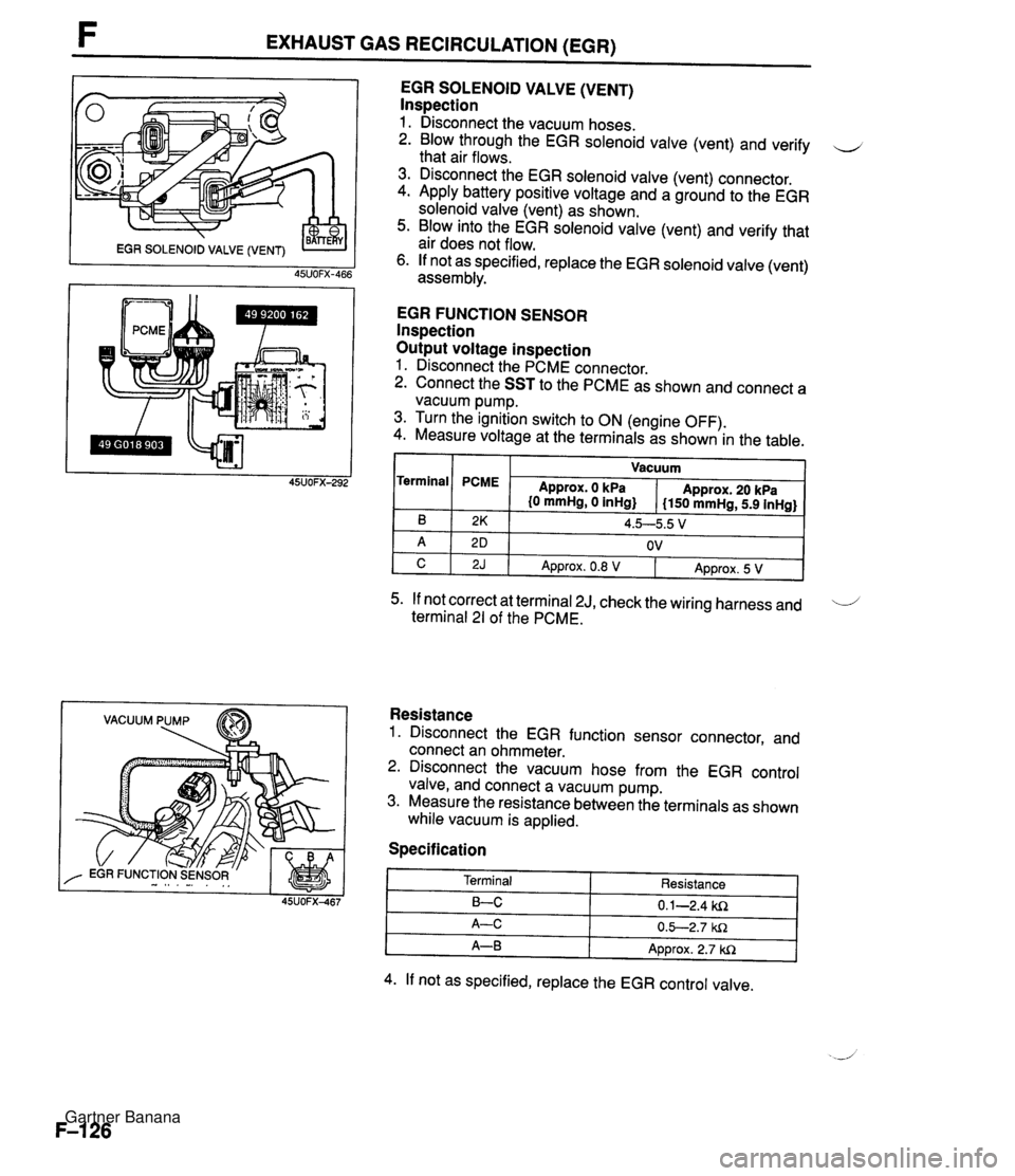
F EXHAUST GAS RECIRCULATION (EGR) VACUUM PUMP EGR SOLENOID VALVE (VENT) lnspection 1. Disconnect the vacuum hoses. 2. Blow through the EGR solenoid valve (vent) and verify u that air flows. 3. Disconnect the EGR solenoid valve (vent) connector. 4. Apply battery positive voltage and a ground to the EGR solenoid valve (vent) as shown. 5. Blow into the EGR solenoid valve (vent) and verify that air does not flow. 6. If not as specified, replace the EGR solenoid valve (vent) assembly. EGR FUNCTION SENSOR lnspection Output voltage inspection 1. Disconnect the PCME connector. 2. Connect the SST to the PCME as shown and connect a vacuum pump. 3. Turn the ignition switch to ON (engine OFF). 4. Measure voltage at the terminals as shown in the table. I I Vacuum I Terminal 5. If not correct at terminal 2J, check the wiring harness and 'i terminal 21 of the PCME. B A C Resistance 1. Disconnect the EGR function sensor connector, and connect an ohmmeter. 2. Disconnect the vacuum hose from the EGR control valve, and connect a vacuum pump. 3. Measure the resistance between the terminals as shown while vacuum is applied. PCME Specification 2K 2 D 2J Approx. 0 kPa {O mmHg, 0 inHg} 4. If not as specified, replace the EGR control valve. Approx. 20 kPa I150 mmHg, 5.9 inHg} 4.5--5.5 V OV Terminal LC A-C A-B Approx. 0.8 V Resistance 0.1-2.4 ki2 0.5-2.7 W1 Approx. 2.7 W1 Approx. 5 V Gartner Banana
Page 284 of 1708

AIC CUT-OFF CONTROL SYSTEM AIC CUT-OFF CONTROL SYSTEM DESCRIPTION An NC cut-off system is used to improve idle smoothness after just starting the engine and to improve - acceleration performance. IGNITION SWITCH POWERTRAIN CONTROL MODULE (ENGINE) CRANKSHAFT POSITION - I DETERMINA- TION OF NC CUT-OFF & $1 . 1 THROTTLE I POSITION SENSOR AIC RELAY IGNITION SWITCH SENSOR 7 After engine has been started - The AJC is cut-off for 2 sec. just after the engine is started. Acceleration The AIC is cut-off upon wide-open-throttle acceleration for approx. 5 sec. Gartner Banana
Page 285 of 1708

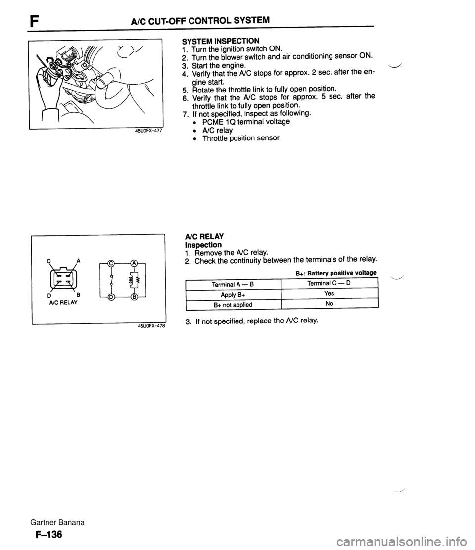
F A/C CUT-OFF CONTROL SYSTEM D B AIC RE LAY SYSTEM INSPECTION 1. Turn the ignition switch ON. 2. Turn the blower switch and air conditioning sensor ON. 3. Start the engine. d 4. Verify that the A/C stops for approx. 2 sec. after the en- gine start. 5. Rotate the throttle link to fully open position. 6. Verify that the A/C stops for approx. 5 sec. after the throttle link to fully open position. 7. If not specified, inspect as following. PCME 1Q terminal voltage A/C relay Throttle position sensor AIC RELAY Inspection 1. Remove the A/C relay. 2. Check the continuity between the terminals of the relay. 3. If not specified, replace the A/C relay. B+: Battery positive voltage Terminal A - B Apply B+ B+ not applied Terminal C - D Yes No Gartner Banana
Page 287 of 1708

COOLANT FAN CONTROL COOLANT FAN CONTROL OUTLINE The PCME controls the coolant fan and the condenser fan to provide more efficient fan control. This 4 improves the performance reliability and stability during idling of an engine. The coolant fan is normal when it start to operate with the data link connector TEN terminal grounded and the accerelator pedal is depressed (Ignition switch ON). IGNITION SWITCH OFF CONDENSER FAN MOTOR PCME RELAY I& MAGNETIC CLUTCH I COOLANT FAN RELAY Q COOLANT FAN MOTOR Gartner Banana
Page 289 of 1708

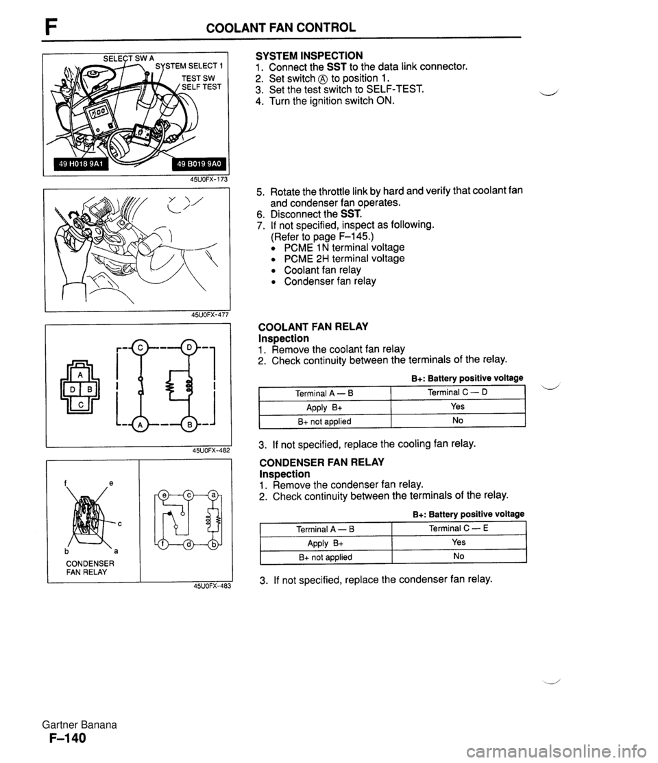
COOLANT FAN CONTROL SYSTEM INSPECTION 1. Connect the SST to the data link connector. 2. Set switch @ to position 1. 3. Set the test switch to SELF-TEST. 4. Turn the ignition switch ON. 5. Rotate the throttle link by hard and verify that coolant fan and condenser fan operates. 6. Disconnect the SST. 7. If not specified, inspect as following. (Refer to page F-145.) PCME 1 N terminal voltage PCME 2H terminal voltage Coolant fan relay Condenser fan relay COOLANT FAN RELAY lnspection 1. Remove the coolant fan relay 2. Check continuity between the terminals of the relay. CONDENSER FAN RELAY 3. If not specified, replace the cooling fan relay. B+: Battery positive voltage CONDENSER FAN RELAY Inspection 1. Remove the condenser fan relay. 2. Check continuity between the terminals of the relay. i/ Terminal A - B Apply B+ B+ not applied 3. If not specified, replace the condenser fan relay. Terminal C - D Yes No B+: Battery positive voltage Terminal A - I3 Apply B+ B+ not applied Terminal C - E Yes No Gartner Banana
Page 294 of 1708

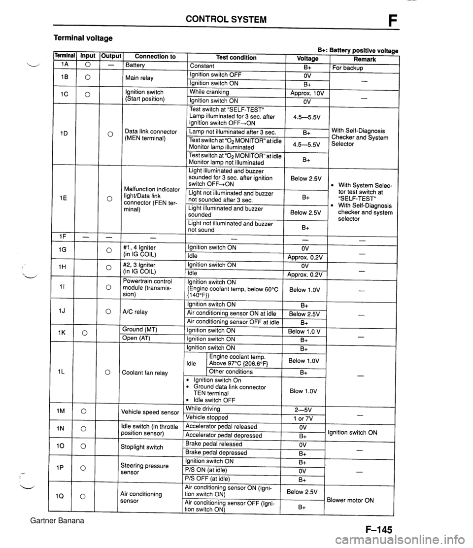
CONTROL SYSTEM F Terminal voltage B+: Battery positive voltage Test condition I Voltage I Remark - - - - - - - - - - - - - - - - - - Connection to Battery Constant Ignition switch OFF Main relay - B+ OV lgnition switch (Start position) For backup - Ignition switch ON While cranking Lamp illuminated for 3 sec. after 1 4.5-5.5V ianition switch OFF+ON 1 B+ Approx. 1 OV Ignition switch ON - - OV Data link connector (MEN terminal) Test switch at "SELF-TEST" .. Lamp not illuminated after 3 sec. Test switch at "02 MONITOR" at idle Monitor lam illuminated & 4.5-5.5v . . I Malfunction indicator IighVData link connector (FEN ter- minal) With Self-Diagnosis Checker and System Selector Test switch at "02 MONITOR" at idle Monitor lamp not illuminated Light illuminated and buzzer sounded for 3 sec. after ignition switch OFF-ON B+ tor tesiswitch at "SELF-TEST" With Self-Diagnosis checker and system selector Below 2.5V 1 Light illuminated and buzzer sounded 1 Below 2.5V I With System Selec- Light not illuminated and buzzer not sounded after 3 sec. I Light not illuminated and buzzer 1 n. 1 B+ not sound I D+ 1 - #I, 4 lgniter (in IG COIL) #2,3 Igniter (in IG COIL) Powertrain control module (transmis- sion) - Ignition switch ON Idle Ignition switch ON Idle lgnition switch ON (Engine coolant temp, below 60°C {I 40°F)) Ignition switch ON AtC relay Air conditioning sensor ON at idle Air conditioning sensor OFF at idle Ground (MT) - OV Approx. 0.2V OV Approx. 0.2V Below 1 .OV B+ Below 2.5V B+ - - - - , * Open (AT) - Ignition switch ON ( Below 1 .O V I Engine coolant temp. I Below .OV I ldle Above 97°C (206.6OF1 Ignition switch ON I I B+ Ignition switch ON Coolant fan relay B+ . - Other conditions lgnition switch On dround data link connector TEN terminal I Blow 1.0" I B+ Vehicle speed sensor ldle switch OFF While driving Vehicle sto~wed ldle switch (in throttle position sensor) 2-5V 1 or 7V . , Accelerator pedal released Accelerator ~edal de~ressed - Stoplight switch OV B+ Brake pedal released Brake ~edal deoressed lgnition switch ON Steering pressure sensor OV B+ I I - Ignition switch ON B+ - PIS ON (at idle) PIS OFF (at idle) Air conditioning sensor Air conditioning sensor ON (Igni- tion switch ON) Air conditioning sensor OFF (Igni- tion switch ON) OV B+ - Below 2.5V B+ Blower motor ON Gartner Banana