ignition MAZDA MX-5 1994 Workshop Manual
[x] Cancel search | Manufacturer: MAZDA, Model Year: 1994, Model line: MX-5, Model: MAZDA MX-5 1994Pages: 1708, PDF Size: 82.34 MB
Page 327 of 1708

IGNITION SYSTEM HIGH-TENSION LEAD Removal l Installation Caution - Reinstall the high-tension leads to their original positions. Incorrect installation can damage the leads and cause power loss, and negatively effect electronic components. Inspection Use an ohmmeter to measure the resistance of each 45uo~x-035 lead. Resistance: 16 kQ per 1 .OO m (3.28 ft) Gartner Banana
Page 328 of 1708

STARTING SYSTEM G STARTING SYSTEM CIRCUIT DIAGRAM I TROUBLESHOOTING Check 1 1 No Magnetic switch gE only clicks when ignition switch is at START Check starter (Refer to page G-23) Check wire harness Check 2 NO MT . . . . 1. Depress clutch pedal 2. Check if voltage between interlock switch (starter side) and ground is approx. 12V AT . . . . 1. Shift into P or N range Check wire harness 2. Check if voltage between parwneutral switch (starter side) and ground is approx. 12v 1. Turn ignition switch to START position 2. Check if voltage between S terminal and ground is approx. 12V Check 3 1 No Check starter magnetic switch (Refer to page G-27) I I Check wire harness I MT . . . . Check if voltage between interlockswitch (igni- tion switch side) and ground is approx. 12V AT . . . . . Check if voltage between parwneutral switch (ignition switch side) and ground is approx. 12v Check starter interlock switch (Refer to page G-28) Check parwneutral switch (Refer to section K) Gartner Banana
Page 335 of 1708

STARTING SYSTEM LIMIT 1 I 45UOGX-043 STARTER INTERLOCK SWITCH (MT) Brush If the brushes are worn beyond the wear limit or if the wear is near the limit, replace the brushes. CONTACT PLATES IGNITION SWITCH mm {in} IG1 ROD Standard Wear limit INTERLOCK SWITCH 62-7 - STARTER MT 17 (0.67) 11.5 (0.45) The clutch pedal must be depressed during starting for battery power to be supplied to the starter. AT 17.5 (0.69) 12.0 (0.47) Inspection 1. Disconnect the interlock switch connector. 2. Check continuity of the switch with an ohmmeter. Pedal Depressed Released Continuity Yes No 1 3. If not as specified, replace the interlock switch. Gartner Banana
Page 412 of 1708

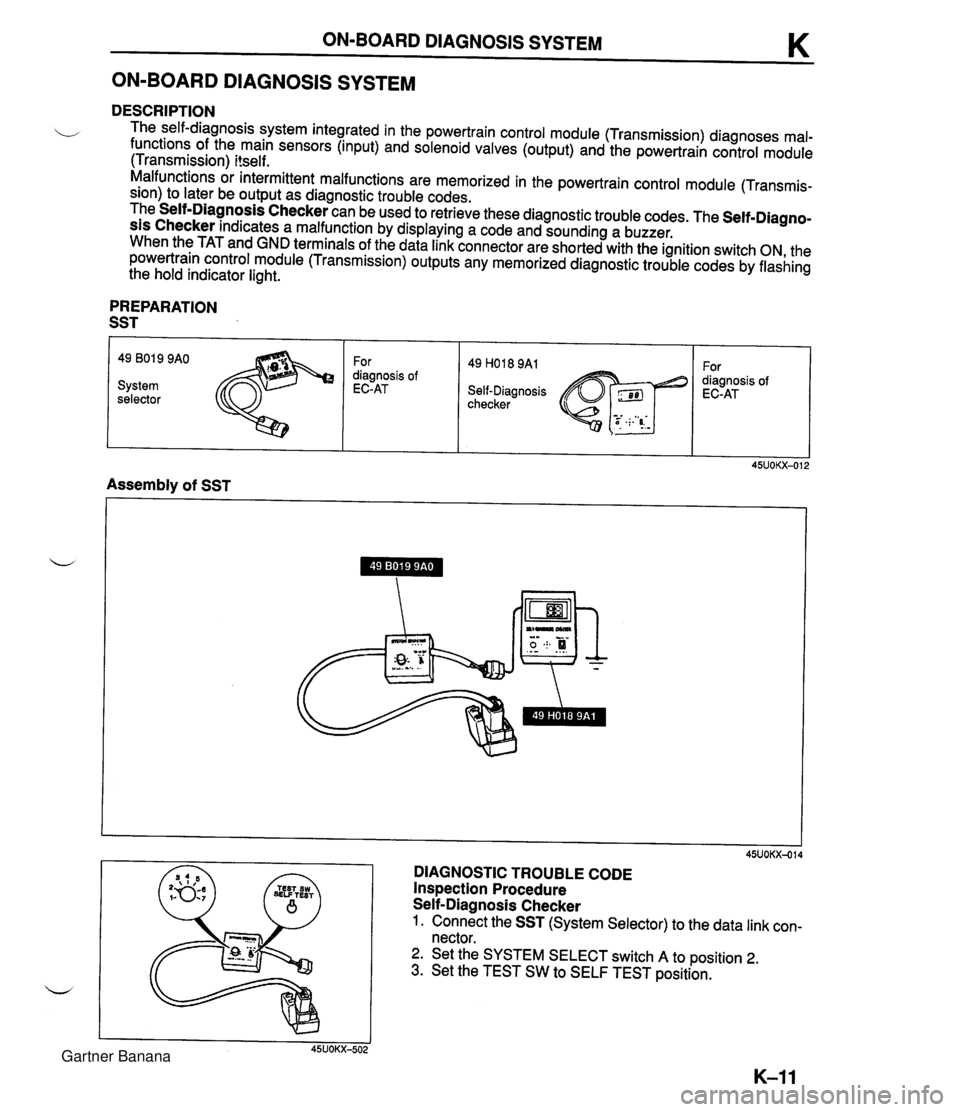
ON-BOARD DIAGNOSIS SYSTEM K ON-BOARD DIAGNOSIS SYSTEM DESCRIPTION The self-diagnosis system integrated in the powertrain control module (Transmission) diagnoses mal- functions of the main sensors (input) and solenoid valves (output) and the powertrain control module (Transmission) itself. Malfunctions or intermittent malfunctions are memorized in the powertrain control module (Transmis- sion) to later be output as diagnostic trouble codes. The Self-Diagnosis Checker can be used to retrieve these diagnostic trouble codes. The Self-Diagno- sis Checker indicates a malfunction by displaying a code and sounding a buzzer. When the TAT and GND terminals of the data link connector are shorted with the ignition switch ON, the powertrain control module (Transmission) outputs any memorized diagnostic trouble codes by flashing the hold indicator light. PREPARATION SST 49 801 9 9AO For 49 H018 9A1 For diagnosis of diagnosis of System EC-AT Self-Diagnosis EC-AT selector checker Assembly of SST DIAGNOSTIC TROUBLE CODE Inspection Procedure Self-Diagnosis Checker 1. Connect the SST (System Selector) to the data link con- nector. 2. Set the SYSTEM SELECT switch A to position 2. 3. Set the TEST SW to SELF TEST position. Gartner Banana
Page 413 of 1708

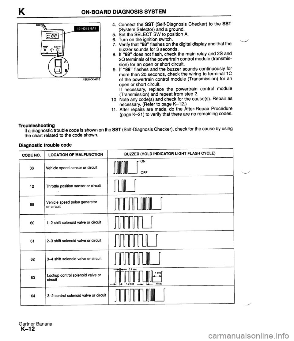
K ON-BOARD DIAGNOSIS SYSTEM Ill I 4. Connect the SST (Self-Diagnosis Checker) to the SST (System Selector) and a ground. 5. Set the SELECT SW to position A. 6. Turn on the ignition switch. ii 7. Verify that "88" flashes on the digital display and that the buzzer sounds for 3 seconds. 8. If "88" does not flash, check the main relay and 2s and 2Q terminals of the powertrain control module (transmis- sion) for an open or short circuit. 9. If "88" flashes and the buzzer sounds continuously for more than 20 seconds, check the wiring to terminal 1C of the powertrain control module (Transmission) for an open or short circuit. If necessary, replace the powertrain control module (Transmission) and repeat from step 2. 10. Note any code(s) and check for the cause(s). Repair as necessary. (Refer to page K-12.) 11. After repairs are made, do the After-Repair Procedure (page K-21) to verify that there are no remaining codes. Troubleshooting If a diagnostic trouble code is shown on the SST (Self-Diagnosis Checker), check for the cause by using the ch&t related to the code shown. Diagnostic trouble code ~U)DE NO. 1 LOCATION OF MALFUNCTION I BUZZER (HOLD INDICATOR LIGHT FLASH CYCLE) Throttle position sensor or circuit 06 Vehicle speed sensor or circuit 55 ON OFF Vehicle speed pulse generator or circuit 60 - 61 1-2 shift solenoid valve or circuit 62 - -- - 3-2 control solenoid valve or circuit 64 T 2-3 shift solenoid valve or circuit 63 - 3-4 shift solenoid valve or circuit -----a Lockup control solenoid valve or circuit -- --i---- - - - audrur - -, -. - 0.4 sec. - --I-& cl.2sec + 2 1.6sec * - 4 sec - - Gartner Banana
Page 415 of 1708

K ON-BOARD DIAGNOSIS SYSTEM - -- )IAGNOSTIC TROUBLE CODE N0.12 THROTTLE POSITION SENSOR ACTION I STEP INSPECTION Are there any poor connections at throttle position sensor and powertrain control module (transmission) connector or termi- nal? Yes Repair or replace connector I Go to next step Go to step 5 Connect a circuit tester to terminal as shown Is input voltage of throttle position sensor (TVO) at powertrain control module (transmission) OK? page K-45 1 (+) term. I (-) term. I Voltage (v)/ Condition 1 Yes No lgnition Go to next step ' 2T Ground valve Approx. closed I 0.8--4.3 position to wide open 1 throttle Go to next step Connect a circuit tester to terminals as shown Is input voltage of throttle position sensor (VREF) at powertrain control module (transmission) OK? page K-44 (+) term. (-) term. Voltage (V) Condition Approx. lgnition 4.55 ;p" 2A Ground Ignition 0 switch OFF Yes Check voltage at terminal 21 of powertrain control module (En- gine) Voltage: 4.5--5.5V (Ignition switch ON) If OK, go to next step If not OK, repair wiring andlor connector Check wiring and connectors form Powertrain control module (transmission) to throttle position sensor If OK, go to next step If not OK, repair wiring andlor connector Is throttle position sensor OK? Section F Yes No Yes Adjust or replace throttle position sensor t@? section F I Replace powertrain control module (transmission) t@? page K-45 is connect the negative battery cable for at least 20 seconds and depress the brake pedal Connect the battery cable and recheck for diagnostic trouble code Is diagnostic trouble code displayed? Daae K-21 Intermittent poor connection Check for cause Gartner Banana
Page 422 of 1708

ON-BOARD DIAGNOSIS SYSTEM K DRIVE AT 50 kmlh (31 mph) I STOP VEHICLE After-Repair Procedure 1. Cancel the memory of diagnostic trouble codes by dis- connecting the negative battery cable for at least 20 se- conds and the depressing the brake pedal. Reconnect the battery cable. 2. Remove the SST (Self-Diagnosis Checker) if con- nected. 3. Drive the vehicle at 50 kmlh (31 mph), and depress the accelerator pedal fully to activate kickdown. Stop the ve- hicle gradually. 4. Connect the SST (Self-Diagnosis Checker) to the data link connector. 5. Turn the ignition switch to ON. 6. Verify that no codes are displayed. Gartner Banana
Page 439 of 1708

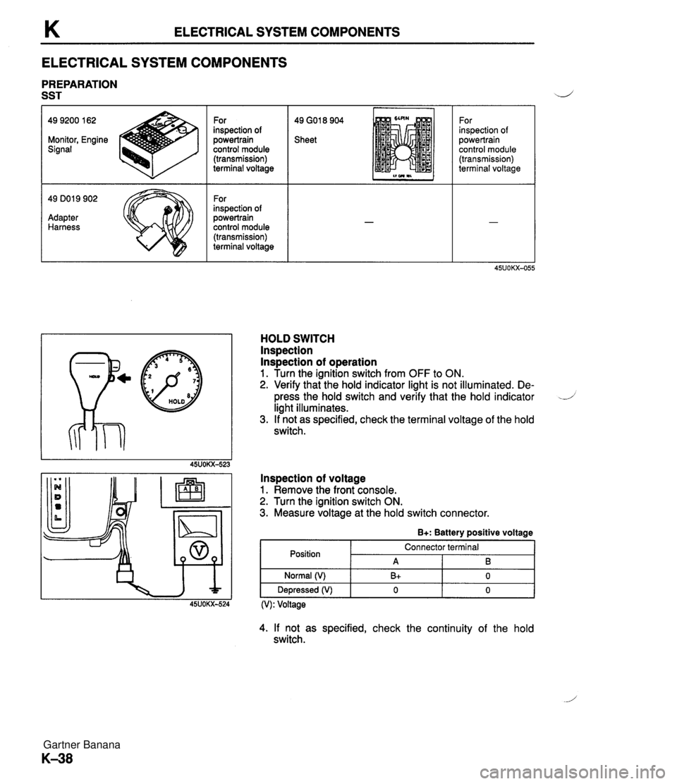
K ELECTRICAL SYSTEM COMPONENTS ELECTRICAL SYSTEM COMPONENTS PREPARATION SST 49 GO1 8 904 Sheet 49 9200 162 Monitor, Engine Signal - 49 DO1 9 902 Adapter Harness For inspection of powertrain control module (transmission) terminal voltage For inspection of powertrain control module (transmission) terminal voltage p@ HOLD For inspection of powertrain control module (transmission) terminal voltage HOLD SWITCH lnspection lnspection of operation 1. Turn the ignition switch from OFF to ON. 2. Verify that the hold indicator light is not illuminated. De- press the hold switch and verify that the hold indicator -J light illuminates. 3. If not as specified, check the terminal voltage of the hold switch. lnspection of voltage 1. Remove the front console. 2. Turn the ignition switch ON. 3. Measure voltage at the hold switch connector. B+: Battery positive voltage Position (V): Voltage Normal (V) Depressed (V) 4. If not as specified, check the continuity of the hold switch. Connector terminal A B+ 0 B 0 0 Gartner Banana
Page 440 of 1708

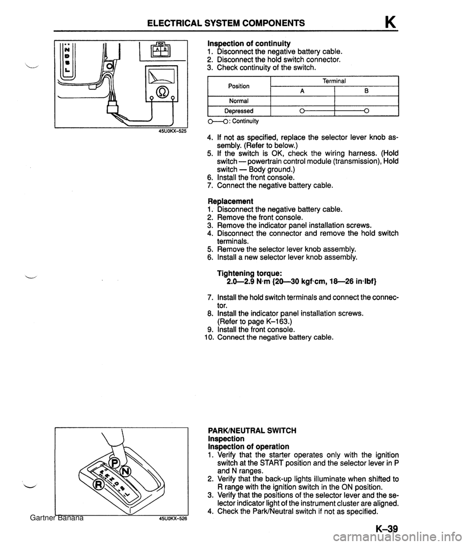
ELECTRICAL SYSTEM COMPONENTS K Replacement 1. Disconnect the negative battery cable. 2. Remove the front console. 3. Remove the indicator panel installation screws. 4. Disconnect the connector and remove the hold switch terminals. 5. Remove the selector lever knob assembly. 6. lnstall a new selector lever knob assembly. lnspection of continuity 1. Disconnect the negative battery cable. 2. Disconnect the hold switch connector. 3. Check continuity of the switch. Tightening torque: 2.0-2.9 N.m (20-30 kgfscm, 18-26 in-lbf) Position Normal Depressed 7. lnstall the hold switch terminals and connect the connec- tor. 8. lnstall the indicator panel installation screws. (Refer to page K-163.) 9. lnstall the front console. 10. Connect the negative battery cable. PARKINEUTRAL SWITCH lnspection lnspection of operation 1. Verify that the starter operates only with the ignition switch at the START position and the selector lever in P and N ranges. 2. Verify that the back-up lights illuminate when shifted to R range with the ignition switch in the ON position. 3. Verify that the positions of the selector lever and the se- lector indicator light of the instrument cluster are aligned. 4. Check the ParkINeutral switch if not as specified. 0--4: Continuity 45UOKX-525 4. If not as specified, replace the selector lever knob as- sembly. (Refer to below.) 5. If the switch is OK, check the wiring harness. (Hold switch - powertrain control module (transmission), Hold switch - Body ground.) 6. lnstall the front console. 7. Connect the negative battery cable. Terminal A 0 B 0 Gartner Banana
Page 444 of 1708

ELECTRICAL SYSTEM COMPONENTS K I POWERTRAIN CONTROL POWERTRAIN CONTROL MODULE (TRANSMISSION) lns~ection 1. kemove the powertrain control module (Transmission). (Refer to page K-45.) 2. Disconnect the control module connectors. 3. Connect the SSTs (Engine Signal Monitor and Adapt- er Harness) to the powertrain control module (Transmis- sion) as shown. 4. Place the SST (sheet) on the Engine Signal Monitor. 5. Turn the ignition switch ON. 6. Measure the terminal voltage at each terminal. 7. If any control module terminal voltage is incorrect, check the related input of output devices and wiring. If no prob- lem is found, replace the powertrain control module (Transmission). Caution Applying voltage to terminals A and B of this SST will damage the SST. Gartner Banana