oil MAZDA MX-5 1994 Owners Manual
[x] Cancel search | Manufacturer: MAZDA, Model Year: 1994, Model line: MX-5, Model: MAZDA MX-5 1994Pages: 1708, PDF Size: 82.34 MB
Page 225 of 1708
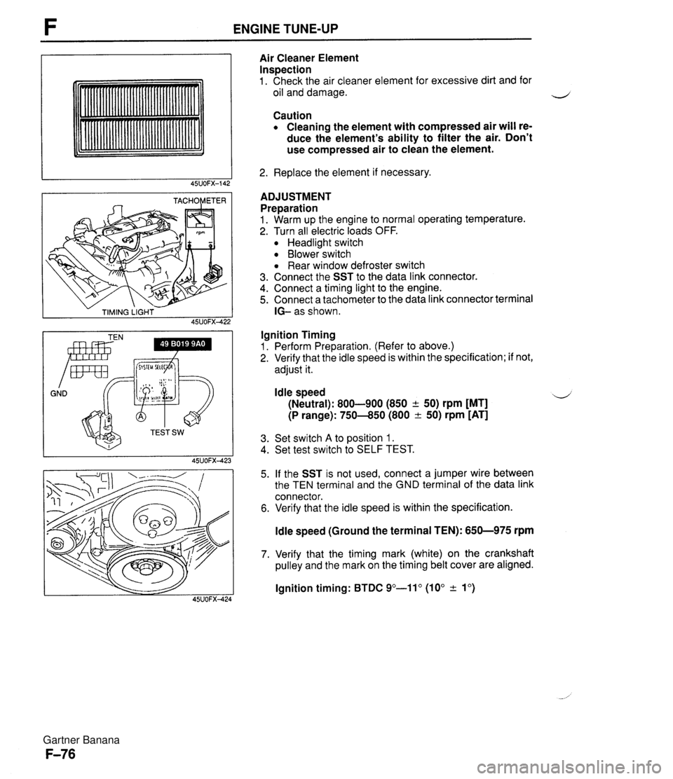
ENGINE TUNE-UP - TIMING LIGHT - 45UOFX422 GND Irnr Air Cleaner Element Inspection 1. Check the air cleaner element for excessive dirt and for oil and damage. Caution Cleaning the element with compressed air will re- duce the element's ability to filter the air. Don't use compressed air to clean the element. 2. Replace the element if necessary. ADJUSTMENT Preparation 1. Warm up the engine to normal operating temperature. 2. Turn all electric loads OFF. Headlight switch Blower switch Rear window defroster switch 3. Connect the SST to the data link connector. 4. Connect a timing light to the engine. 5. Connect a tachometer to the data link connector terminal IG- as shown. Ignition Timing 1. Perform Preparation. (Refer to above.) 2. Verify that the idle speed is within the specification; if not, adjust it. Idle speed 4 (Neutral): 800-900 (850 + 50) rpm [MT] (P range): 750-850 (800 & 50) rpm [AT] 3. Set switch A to position 1. 4. Set test switch to SELF TEST. 5. If the SST is not used, connect a jumper wire between the TEN terminal and the GND terminal of the data link connector. 6. Verify that the idle speed is within the specification. ldle speed (Ground the terminal TEN): 650-975 rpm 7. Verify that the timing mark (white) on the crankshaft pulley and the mark on the timing belt cover are aligned. lgnition timing: BTDC 9"-11" (10" & lo) Gartner Banana
Page 226 of 1708
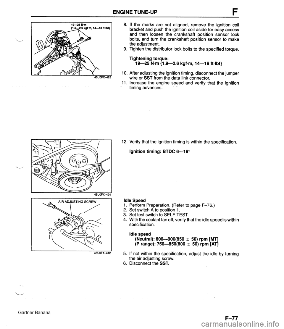
ENGINE TUNE-UP 8. If the marks are not aligned, remove the ignition coil bracket and push the ignition coil aside for easy access and then loosen the crankshaft position sensor lock bolts, and turn the crankshaft position sensor to make the adjustment. 9. Tighten the distributor lock bolts to the specified torque. Tightening torque: 19-25 N-m (1.9-2.6 kgfem, 14--18 ftqlbf) 10. After adjusting the ignition timing, disconnect the jumper wire or SST from the data link connector. 11. Increase the engine speed and verify that the ignition timing advances. 12. Verify that the ignition timing is within the specification. Ignition timing: BTDC 6-18' ldle Speed 1. Perform Preparation. (Refer to page F-76.) 2. Set switch A to position 1. 3. Set test switch to SELF TEST. 4. With the coolant fan off, verify that the idle speed is within specification. ldle speed (Neutral): 800-900(850 + 50) rpm [MT] (P range): 750--850(800 -c 50) rpm [AT] 5. If not within the specification, adjust the idle by turning the air adjusting screw. 6. Disconnect the SST. Gartner Banana
Page 232 of 1708
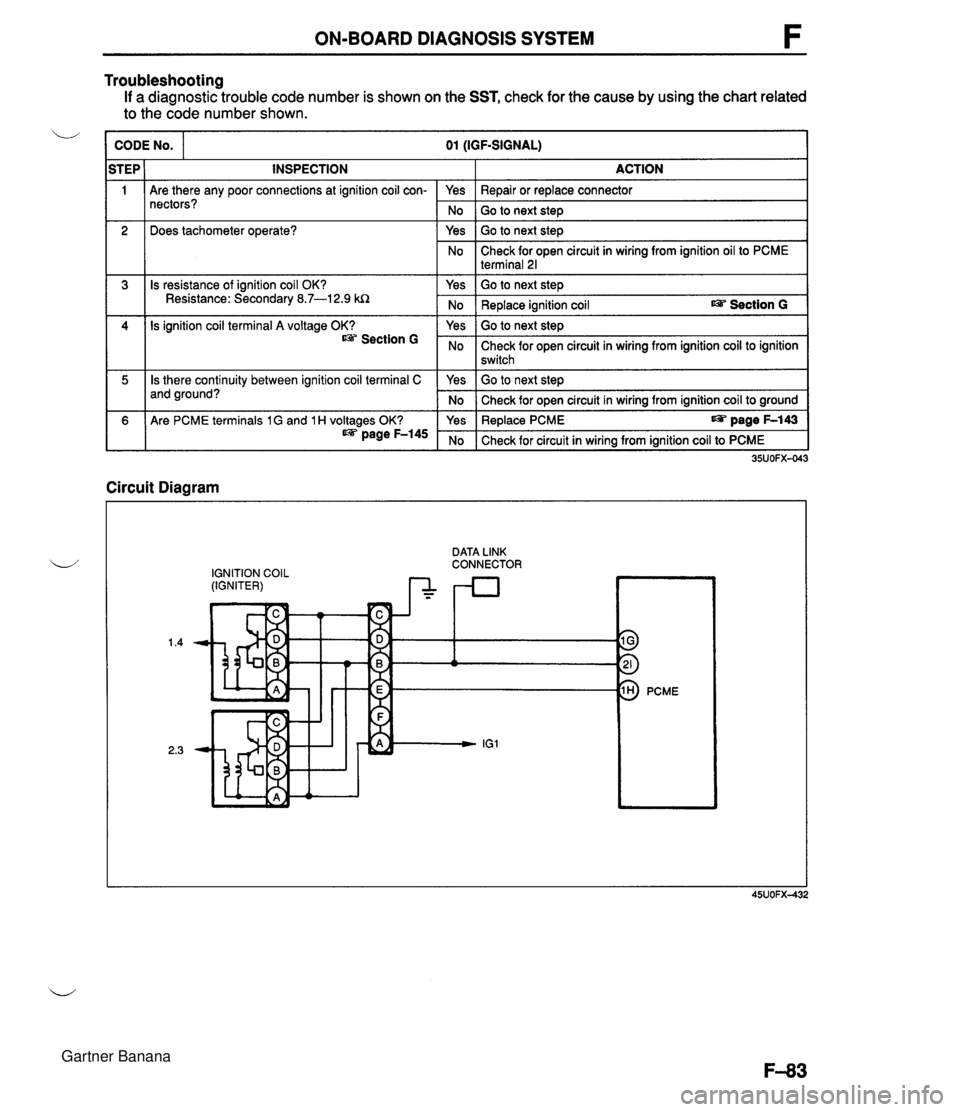
ON-BOARD DIAGNOSIS SYSTEM Troubleshooting If a diagnostic trouble code number is shown on the SST, check for the cause by using the chart related to the code number shown. CODE NO. 01 (IGF-SIGNAL) 1 Are there any poor connections at ignition coil con- nectors? 2 STEP 1 INSPECTION Does tachometer operate? 3 = 1 Is there continuity between ignition coil terminal C and ground? ACTION Is resistance of ignition coil OK? Resistance: Secondary 8.7-1 2.9 kQ 4 1 Are PCME terminals 1 G and 1 H voltages OK? @s page F-145 Is ignition coil terminal A voltage OK? Section G Circuit Diagram IGNITION COIL (IGNITER) Yes 1 Repair or replace connector I No Yes Go to next step Go to next step No Yes Check for open circuit in wiring from ignition oil to PCME terminal 21 Go to next step No Yes Yes I Replace PCME page F-143 I Replace ignition coil rn Section G Go to next step No Yes No - - No I Check for circuit in wiring from ignition coil to PCME I 35UOFX-043 Check for open circuit in wiring from ignition coil to ignition switch Go to next step Check for open circuit in wiring from ignition coil to ground DATA LINK - . . . . . - . . CONNECTOR 9 3 PCME Gartner Banana
Page 265 of 1708
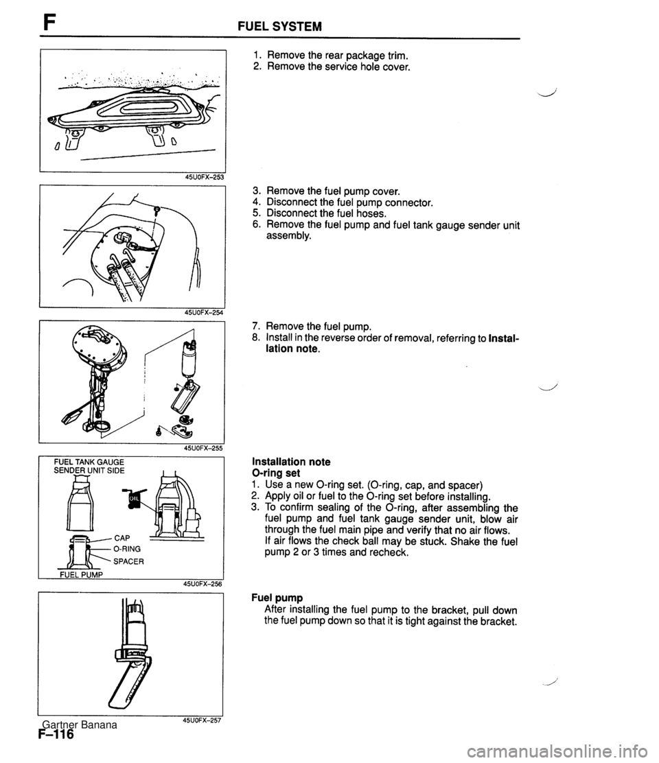
FUEL SYSTEM -- FUEL TANK GAUGE SENDER UNIT SIDE FUEL PUMP 45UOFX-256 1. Remove the rear package trim. 2. Remove the service hole cover. 3. Remove the fuel pump cover. 4. Disconnect the fuel pump connector. 5. Disconnect the fuel hoses. 6. Remove the fuel pump and fuel tank gauge sender unit assembly. 7. Remove the fuel pump. 8. Install in the reverse order of removal, referring to Instal- lation note. Installation note O-ring set 1. Use a new O-ring set. (O-ring, cap, and spacer) 2. Apply oil or fuel to the O-ring set before installing. 3. To confirm sealing of the O-ring, after assembling the fuel pump and fuel tank gauge sender unit, blow air through the fuel main pipe and verify that no air flows. If air flows the check ball may be stuck. Shake the fuel pump 2 or 3 times and recheck. Fuel pump After installing the fuel pump to the bracket, pull down the fuel pump down so that it is tight against the bracket. Gartner Banana
Page 270 of 1708
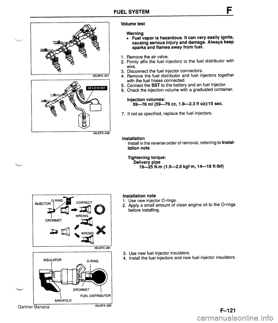
FUEL SYSTEM Volume test Warning Fuel vapor is hazardous. It can very easily ignite, causing serious injury and damage. Always keep sparks and flames away from fuel. 1. Remove the air valve. 2. Firmly affix the fuel injectors to the fuel distributor with wire. 3. Disconnect the fuel injector connectors. 4. Remove the fuel distributor and fuel injectors together with the fuel hoses connected. 5. Connect the SST to the battery and an fuel injector. 6. Check the injection volume with a graduated container. Injection volumes: 59-76 ml (59-76 cc, 1.8-2.3 fl oz}/15 sec. 7. If not as specified, replace the fuel injectors. lnstallation Install in the reverse order of removal, referring to Instal- lation note. Tightening torque: Delivery pipe 19-25 N.m (1 .%2.6 kgfm, 14--18 ft4bf) FUEL DISTRIBUTOR MANIFOLD C 45UOFX-282 Installation note 1. Use new injector O-rings. 2. Apply a small amount of clean engine oil to the O-rings before installing. 45UOFX-281 INSULATOR O-RING 3. Use new fuel injector insulators. 4. Install the fuel injectors and new fuel injector insulators. Gartner Banana
Page 294 of 1708
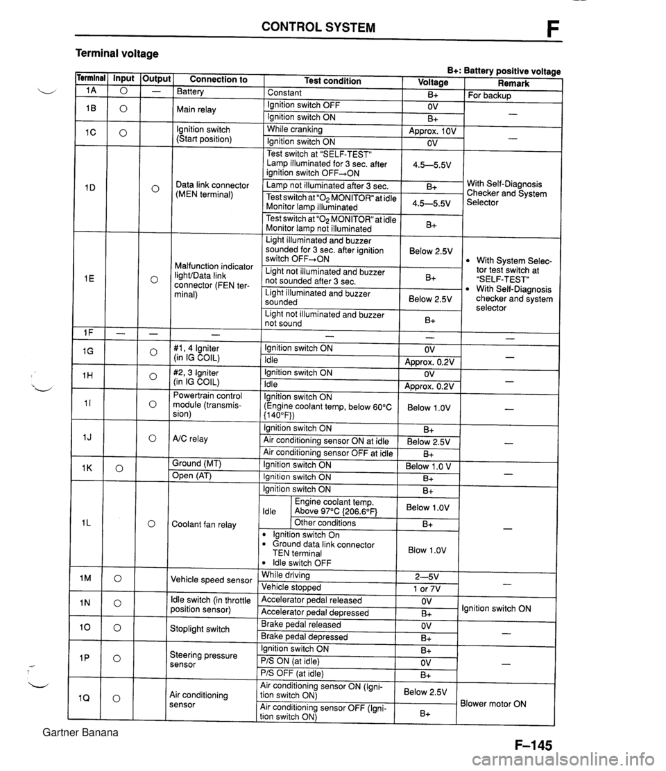
CONTROL SYSTEM F Terminal voltage B+: Battery positive voltage Test condition I Voltage I Remark - - - - - - - - - - - - - - - - - - Connection to Battery Constant Ignition switch OFF Main relay - B+ OV lgnition switch (Start position) For backup - Ignition switch ON While cranking Lamp illuminated for 3 sec. after 1 4.5-5.5V ianition switch OFF+ON 1 B+ Approx. 1 OV Ignition switch ON - - OV Data link connector (MEN terminal) Test switch at "SELF-TEST" .. Lamp not illuminated after 3 sec. Test switch at "02 MONITOR" at idle Monitor lam illuminated & 4.5-5.5v . . I Malfunction indicator IighVData link connector (FEN ter- minal) With Self-Diagnosis Checker and System Selector Test switch at "02 MONITOR" at idle Monitor lamp not illuminated Light illuminated and buzzer sounded for 3 sec. after ignition switch OFF-ON B+ tor tesiswitch at "SELF-TEST" With Self-Diagnosis checker and system selector Below 2.5V 1 Light illuminated and buzzer sounded 1 Below 2.5V I With System Selec- Light not illuminated and buzzer not sounded after 3 sec. I Light not illuminated and buzzer 1 n. 1 B+ not sound I D+ 1 - #I, 4 lgniter (in IG COIL) #2,3 Igniter (in IG COIL) Powertrain control module (transmis- sion) - Ignition switch ON Idle Ignition switch ON Idle lgnition switch ON (Engine coolant temp, below 60°C {I 40°F)) Ignition switch ON AtC relay Air conditioning sensor ON at idle Air conditioning sensor OFF at idle Ground (MT) - OV Approx. 0.2V OV Approx. 0.2V Below 1 .OV B+ Below 2.5V B+ - - - - , * Open (AT) - Ignition switch ON ( Below 1 .O V I Engine coolant temp. I Below .OV I ldle Above 97°C (206.6OF1 Ignition switch ON I I B+ Ignition switch ON Coolant fan relay B+ . - Other conditions lgnition switch On dround data link connector TEN terminal I Blow 1.0" I B+ Vehicle speed sensor ldle switch OFF While driving Vehicle sto~wed ldle switch (in throttle position sensor) 2-5V 1 or 7V . , Accelerator pedal released Accelerator ~edal de~ressed - Stoplight switch OV B+ Brake pedal released Brake ~edal deoressed lgnition switch ON Steering pressure sensor OV B+ I I - Ignition switch ON B+ - PIS ON (at idle) PIS OFF (at idle) Air conditioning sensor Air conditioning sensor ON (Igni- tion switch ON) Air conditioning sensor OFF (Igni- tion switch ON) OV B+ - Below 2.5V B+ Blower motor ON Gartner Banana
Page 302 of 1708
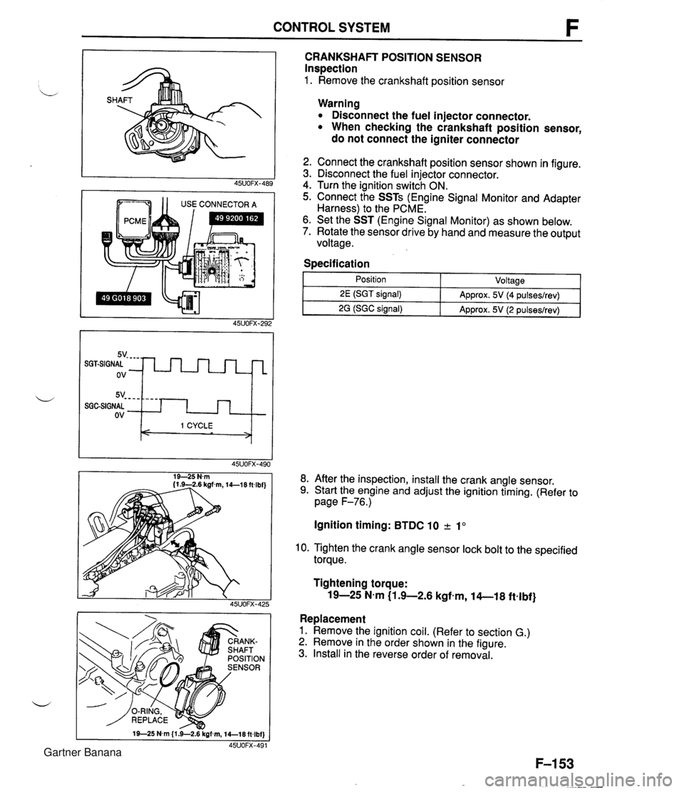
CONTROL SYSTEM 1 1 USE CONNECTOR A CRANKSHAFT POSITION SENSOR Inspection 1. Remove the crankshaft position sensor 5v- - - - SGGSIGNAL ov Warning Disconnect the fuel injector connector. When checking the crankshaft position sensor, do not connect the igniter connector - - - - I 1 CYCLE < > 2. Connect the crankshaft position sensor shown in figure. 3. Disconnect the fuel injector connector. 4. Turn the ignition switch ON. 5. Connect the SSTs (Engine Signal Monitor and Adapter Harness) to the PCME. 6. Set the SST (Engine Signal Monitor) as shown below. 7. Rotate the sensor drive by hand and measure the output voltage. Specification I 1 - Position - ~oltaael 8. After the inspection, install the crank angle sensor. 9. Start the engine and adjust the ignition timing. (Refer to page F-76.) 2E (SGT signal) 2G (SGC signal) Ignition timing: BTDC 10 2 1" Approx. 5V (4 pulseslrev) Approx. 5V (2 pulseslrev) 10. Tighten the crank angle sensor lock bolt to the specified torque. Tightening torque: 19-25 N-m (1 .+2.6 kgfem, 14-1 8 ftelbf} Replacement 1. Remove the ignition coil. (Refer to section G.) 2. Remove in the order shown in the figure. 3. Install in the reverse order of removal. Gartner Banana
Page 303 of 1708
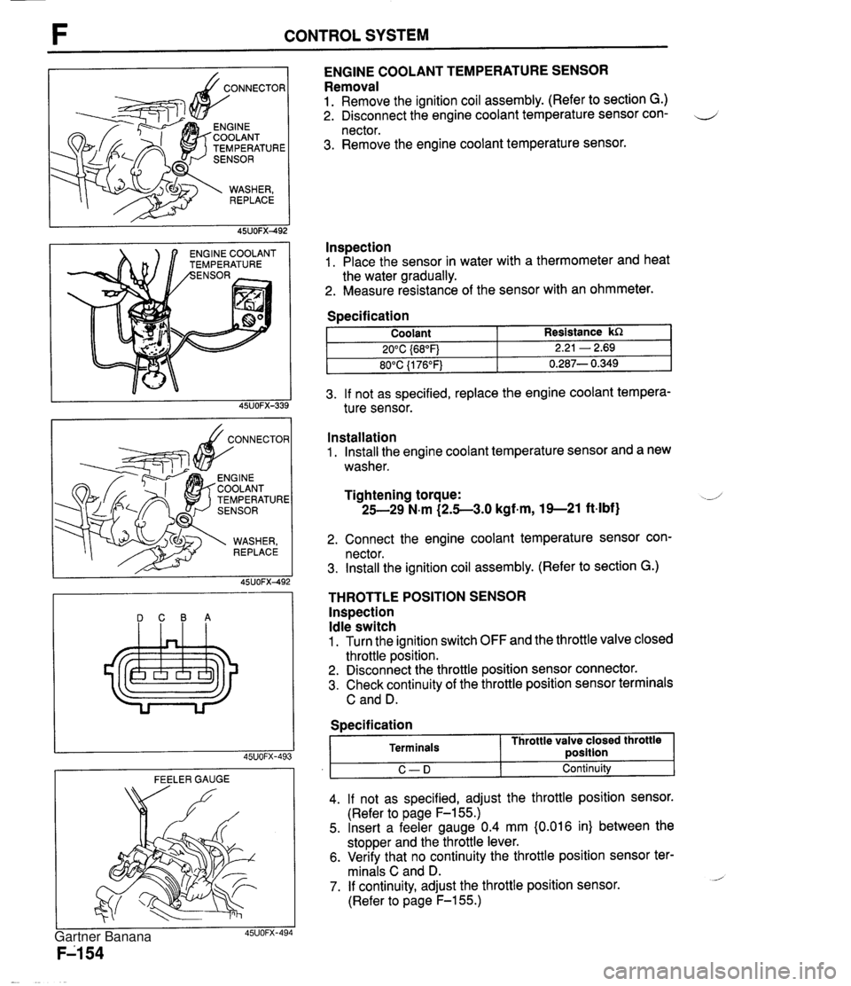
CONTROL SYSTEM TEMPERATURE NGlNE COOLANT EMPERATURE ENGINE COOLANT TEMPERATURE SENSOR Removal 1. Remove the ignition coil assembly. (Refer to section G.) 2. Disconnect the engine coolant temperature sensor con- 4 nector. 3. Remove the engine coolant temperature sensor. lnspection 1. Place the sensor in water with a thermometer and heat the water gradually. 2. Measure resistance of the sensor with an ohmmeter. 3. If not as specified, replace the engine coolant tempera- ture sensor. Specification DCBA Coolant 20°C {68"F) 80°C {I 76°F) FEELER GAUGE Resistance kR 2.21 - 2.69 0.287- 0.349 Installation 1. Install the engine coolant temperature sensor and a new washer. Tightening torque: -J 25-29 N.m (2.5-3.0 kgf-m, 19--21 ft-lbf) 2. Connect the engine coolant temperature sensor con- nector. 3. Install the ignition coil assembly. (Refer to section G.) THROTTLE POSITION SENSOR lnspection Idle switch 1. Turn the ignition switch OFF and the throttle valve closed throttle position. 2. Disconnect the throttle position sensor connector. 3. Check continuity of the throttle position sensor terminals C and D. I C-D I Continuity 4. If not as specified, adjust the throttle position sensor. (Refer to page F-155.) 5. Insert a feeler gauge 0.4 mm {0.016 in) between the stopper and the throttle lever. 6. Verify that no continuity the throttle position sensor ter- minals C and D. - 7. If continuity, adjust the throttle position sensor. (Refer to page F-155.) Specification Terminals Throttle valve closed throttle ~osition Gartner Banana
Page 308 of 1708

Before beginning any service procedure. refer to section T of this manual for air bag system service warnings and audio antitheft system alarm conditions . ENGINE ELECTRICAL SYSTEM INDEX ....................................... G- 2 OUTLINE ..................................... G- 3 SPECIFICATIONS ........................... G- 3 TROUBLESHOOTING GUIDE .................. G- 4 CHARGING SYSTEM .......................... G- 6 PREPARATION ............................. G- 6 CIRCUIT DIAGRAM ......................... G- 6 TROUBLESHOOTING ....................... G- 7 BATTERY .................................. G- 8 ALTERNATOR .............................. G-10 DRIVE BELT ................................ G-13 IGNITION SYSTEM ............................ G-15 PREPARATION ............................. G-15 CIRCUIT DIAGRAM ......................... G-15 TROUBLESHOOTING ....................... G-16 IGNITION TIMING ........................... G-17 SPARK PLUG ............................... G-18 IGNITION COIL ............................. G-19 IGNITER ................................... G-19 HIGH-TENSION LEAD ....................... G-20 STARTING SYSTEM ........................... G-21 CIRCUIT DIAGRAM ......................... G-21 TROUBLESHOOTING ....................... G-21 STARTER .................................. G-22 STARTER INTERLOCK SWITCH (MT) ......... G-28 45UOGX401 Gartner Banana
Page 309 of 1708

G INDEX INDEX 1. Battery lnspection . . . . . . . . . . . . . . . . . page G- 8 Recharging . . . . . . . . . . . . . . . . page G- 9 Replacement . . . . . . . . . . . . . . page G-10 2. Alternator Removal / lnstallation . . . . . . . page G-10 Disassembly / Assembly . . . . page G-11 lnspection . . . . . . . . . . . . . . . . . page G-12 3. Drive belt lnspection . . . . . . . . . . . . . . . . . page G-13 Adjustment . . . . . . . . . . . . . . . . page G-14 4. Spark plug Removal / Installation . . . . . . . page G-18 Spark test . . . . . . . . . . . . . . . . . page G-18 lnspection . . . . . . . . . . . . . . . . . page G-18 5. Ignition coil lnspection . . . . . . . . . . . . . . . . . page G-19 Replacement . . . . . . . . . . . . . . page G-19 6. Igniter (in ignition coil) lnspection . . . . . . . . . . . . . . . . . page G-19 7. High-tension lead Removal / lnstallation . . . . . . . page G-20 lnspection . . . . . . . . . . . . . . . . . page G-20 8. Starter Removal / lnstallation . . . . . . . page G-22 Performance lnspection . . . . . page G-23 Disassembly / Assembly . . . . page G24 -' lnspection . . . . . . . . . . . . . . . . . page G26 9. Starter interlock switch (MT) lnspection . . . . . . . . . . . . . . . . . page G-28 Gartner Banana