transmission MAZDA MX-5 1994 Workshop Manual
[x] Cancel search | Manufacturer: MAZDA, Model Year: 1994, Model line: MX-5, Model: MAZDA MX-5 1994Pages: 1708, PDF Size: 82.34 MB
Page 459 of 1708

K TRANSMISSION 21. Loosen the fourth gear band servo locknut and tighten the piston stem. 22. Mark the fourth gear case and oil pump for proper reas- sembly. 23. Install the SST to the oil pump assembly. 24. Slowly remove the oil pump from the transmission case by evenly sliding the weights of the SST. 25. Remove the SST from the oil pump. 26. Loosen the piston stem of the fourth gear band servo. Remove the fourth gear connecting shell and fourth gear planetary gear unit (fourth gear sun gear, fourth gear planetary pinion carrier, fourth gear clutch hub), and di- rect clutch. 27. Remove the fourth gear brake band, and hold it together with a piece of wire as shown in the figure. 28. Remove the band strut. Gartner Banana
Page 460 of 1708
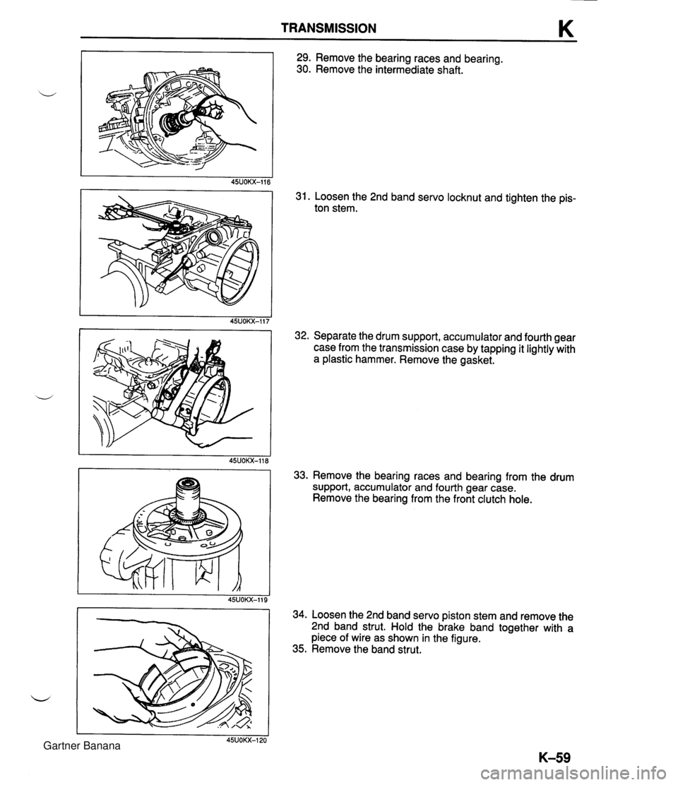
TRANSMISSION K 29. Remove the bearing races and bearing. 30. Remove the intermediate shaft. I 45UOKX-116 31. Loosen the 2nd band servo locknut and tighten the pis- ton stem. I 1 45UOKX-117 32. Separate the drum support, accumulator and fourth gear case from the transmission case by tapping it lightly with a plastic hammer. Remove the gasket. u 45UOKX-118 Remove the bearing races and bearing from the drum support, accumulator and fourth gear case. Remove the bearing from the front clutch hole. Loosen the 2nd band servo piston stem and remove the 2nd band strut. Hold the brake band together with a piece of wire as shown in the figure. Remove the band strut. Gartner Banana
Page 461 of 1708
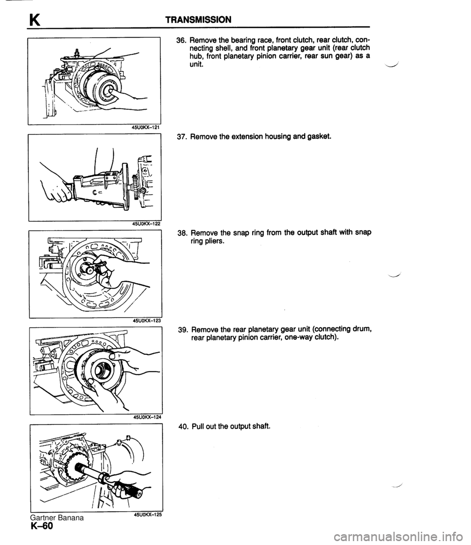
K TRANSMISSION 36. Remove the bearing race, front clutch, rear clutch, con- necting shell, and front planetary gear unit (rear clutch hub, front planetary pinion carrier, rear sun gear) as a unit. d 37. Remove the extension housing and gasket. 38. Remove the snap ring from the output shaft with snap ring pliers. 39. Remove the rear planetary gear unit (connecting drum, rear planetary pinion carrier, one-way clutch). 40. Pull out the output shaft. Gartner Banana
Page 462 of 1708

TRANSMISSION K 41. Remove the oil distributor. 42. Remove the bearing. TORQUE CONVERTER Inspection 1. Check the outside of the converter for damage and cracks, and replace the torque converter if there is any problem. 2. Check for rust on the pilot hub or on the boss, and re- move the rust completely if there is any. Washing inside the converter 1. Drain any ATF remaining in the converter. 2. Pour in solvent (0.5 L, 0.5 US qt, 0.4 Imp qt). 3. Shake the converter to clean the inside. Pour out the sol- vent. 4. Clean the inside of the converter with compressed air so that the inside is completely empty. 5. Pour in ATF. 6. Shake the converter to clean the inside. Pour out the ATF. Gartner Banana
Page 463 of 1708
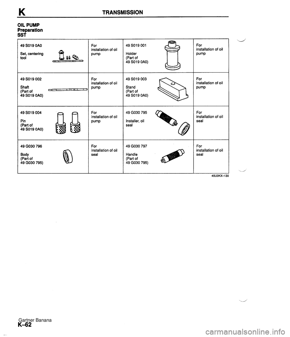
K TRANSMISSION OIL PUMP Preparation SST 49 SO1 9 OAO Set, centering tool Shaft (Part of P 49 SO 1 9 OAO) 49 SO1 9 004 Pin (Part of 49 SO1 9 OAO) Body (Part of 49 GO30 795) For installation of oil P'""P For installation of oil Pump For installation of oil Pu""P For installation of oil seal 49 SO19 001 Holder (Part of 49 SO 1 9 OAO) 49 SO1 9 003 Stand (Part of 49 SO1 9 OAO) 49 GO30 795 Installer, oil seal Handle (Part of 49 GO30 795) For installation of oil Pump For installation of oil Pump For installation of oil seal For installation of oil seal Gartner Banana
Page 464 of 1708

TRANSMISSION K Disassembly I lnspection I Assembly 1. Disassemble in the order shown in the figure, referring to Disassembly Note. 2. Inspect all parts, and repair or replace as necessary. ,, 3. Assemble in the reverse order of disassembly, referring to Assembly procedure. 0 APPLY PETROLEUM JELLY 1. Snap ring 9. Inner gear 2. Sensing rotor Disassembly note .......... page K-64 3. Bearing Inspection ................. page K-64 4. Input shaft 10. Outer gear 5. O-ring Disassembly note .......... page K-64 6. Oil pump cover Inspection ................. page K-64 Disaseembly note .......... page K-64 11. Oil seal Inspection ................. page K-64 12. Roll pin 7. Oil pump housing 13. Plug Inspection ................. page K-64 14. Spring 8. O-ring Inspection ................. page K-65 15. Lockup control valve Gartner Banana
Page 465 of 1708
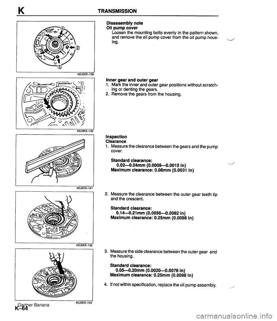
K TRANSMISSION Disassembly note Oil pump cover Loosen the mounting bolts evenly in the pattern shown, and remove the oil pump cover from the oil pump hous- ,-, ing . Inner gear and outer gear 1. Mark the inner and outer gear positions without scratch- ing or denting the gears. 2. Remove the gears from the housing. Inspection Clearance 1. Measure the clearance between the gears and the pump cover. Standard clearance: 0.02-0.04mm (0.0008-0.0015 in) Maximum clearance: 0.08mm (0.0031 in) 2. Measure the clearance between the outer gear teeth tip and the crescent. Standard clearance: 0.1 4-O.21 mm (0.0056-4.0082 in) Maximum clearance: 0.25mm (0.0098 in) 3. Measure the side clearance between the outer gear and the housing. Standard clearance: 0.05--0.20mm (0.0020--0.0078 in) Maximum clearance: 0.25mm (0.0098 in) 4. If not within specification, replace the oil pump assembly. -/' Gartner Banana
Page 466 of 1708
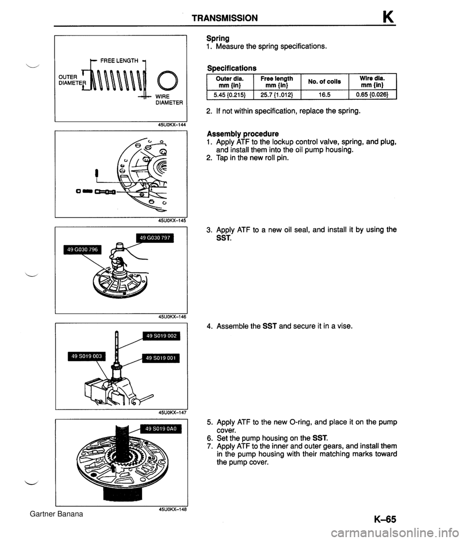
TRANSMISSION K WIRE DIAMETER Spring 1. Measure the spring specifications. Soecifications I Outer dia. I Free Ienpth I cO1ls I :Ired$ mm {in) mm {in) I 2. If not within specification, replace the spring. Assembly procedure 1. Apply ATF to the lockup control valve, spring, and plug, and install them into the oil pump housing. 2. Tap in the new roll pin. 3. Apply ATF to a new oil seal, and install it by using the SST. 4. Assemble the SST and secure it in a vise. 5. Apply ATF to the new O-ring, and place it on the pump cover. 6. Set the pump housing on the SST. 7. Apply ATF to the inner and outer gears, and install them in the pump housing with their matching marks toward the pump cover. Gartner Banana
Page 467 of 1708
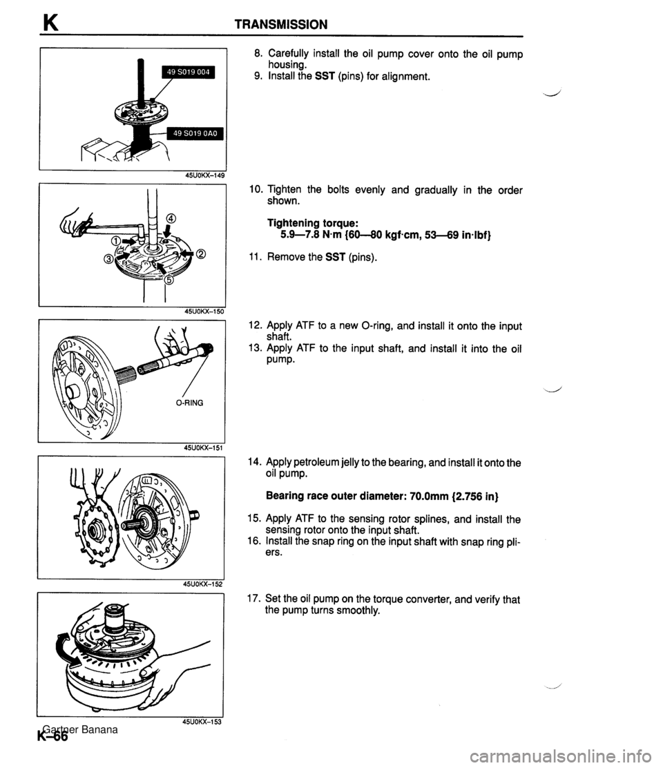
K TRANSMISSION 8. Carefully install the oil pump cover onto the oil pump housing. 9. Install the SST (pins) for alignment. J 10. Tighten the bolts evenly and gradually in the order shown. Tightening torque: 5.9-7.8 N-m (6040 kgf-cm, 53-69 in-lbf) 11. Remove the SST (pins). 12. Apply ATF to a new O-ring, and install it onto the input shaft. 13. Apply ATF to the input shaft, and install it into the oil Pump. 14. Apply petroleum jelly to the bearing, and install it onto the oil pump. Bearing race outer diameter: 70.0mm (2.756 in) 15. Apply ATF to the sensing rotor splines, and install the sensing rotor onto the input shaft. 16. Install the snap ring on the input shaft with snap ring pli- ers. 17. Set the oil pump on the torque converter, and verify that the pump turns smoothly. Gartner Banana
Page 468 of 1708
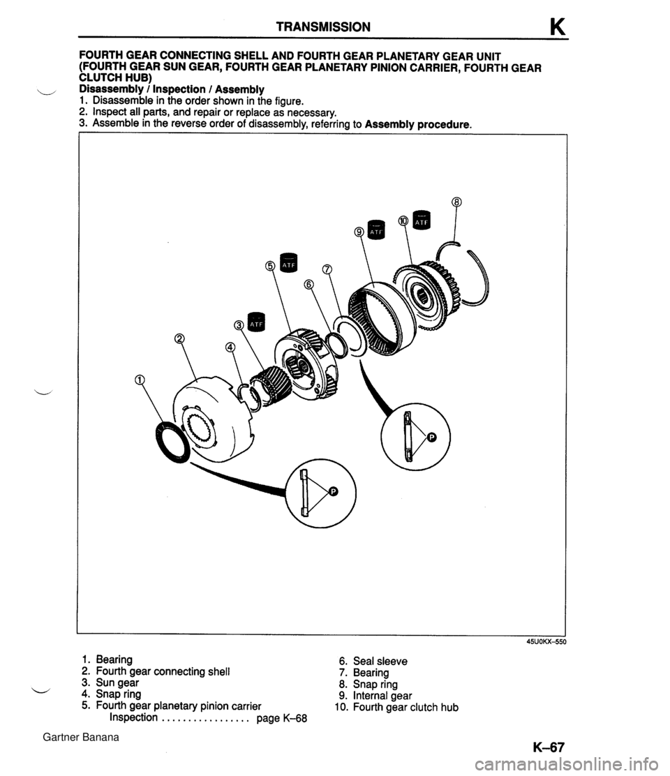
TRANSMISSION K FOURTH GEAR CONNECTING SHELL AND FOURTH GEAR PLANETARY GEAR UNIT (FOURTH GEAR SUN GEAR, FOURTH GEAR PLANETARY PINION CARRIER, FOURTH GEAR CLUTCH HUB) ,, Disassembly / Inspection l Assembly 1. Disassemble in the order shown in the figure. 2. Inspect all parts, and repair or replace as necessary. 3. Assemble in the reverse order of disassembly, referring to Assembly procedure. 1. Bearing 6. Seal sleeve 2. Fourth gear connecting shell 7. Bearing 3. Sun gear 8. Snap ring 4. Snap ring 9. Internal gear 5. Fourth gear planetary pinion carrier 10. Fourth gear clutch hub Inspection . . . . . . . . . . . . . . . . . page K-68 Gartner Banana