oil type MAZDA MX-5 1994 User Guide
[x] Cancel search | Manufacturer: MAZDA, Model Year: 1994, Model line: MX-5, Model: MAZDA MX-5 1994Pages: 1708, PDF Size: 82.34 MB
Page 158 of 1708

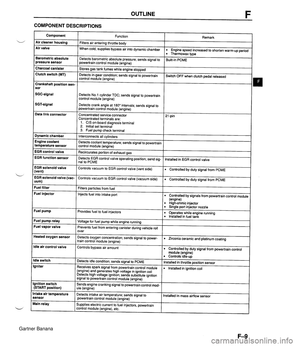
OUTLINE F COMPONENT DESCRIPTIONS Component Air cleaner housing Air valve Remark Function Filters air entering throttle body When cold, supplies bypass air into dynamicchamber w Engine speed increased to shorten warm-up period Thermowax type Barometric absolute pressure sensor Detects barometric absolute pressure; sends signal to powertrain control module (engine) 3uilt-in PCME Charcoal canister Clutch switch (MT) Stores gas tank fumes while engine stopped Detects in-gear condition: sends signal to powertrain control module (engine) --- ~witch OFF when clutch pedal released Crankshaft position sen- sor Detects No.1 cylinder TDC; sends signal to powertrain control module (engine) Detects crank angle at 180" intervals; sends signal to powertrain control module (engine) Data link connector Concentrated service connector Concentrated terminals are: 1. CIS on-board diagnosis terminal 2. Initial set terminal 3. Fuel pump check terminal Dynamic chamber Interconnects all cylinders Detects coolant temperature; sends signal to powertrain control module (engine) Recircurates oortion of exhaust aas Engine coolant temperature sensor EGR control valve lnstalled in EGR control valve EGR function sensor Detects EGR control valve operating position; send sig- nal to PCME EGR solenoid valve (vent) Controls vacuum to EGR control valve (vent side) Controlled by duty signal from PCME . - EGR solenoid valve (vac- Controls vacuum to EGR control valve (vacuum side) 0 Controlled by duty signal from PCME uum) Fuel filter Filters particles from fuel Injects fuel into intake port Fuel injector Controlled by signals from powertrain control module (engine) High-ohmic injector 0 Sinale port injector nozzle Fuel pump Provides fuel to fuel injectors 0 operates while engine running lnstalled in fuel tank Fuel pump relay Voltage for fuel pump while engine running Fuel vapor valve Prevents fuel from entering canister during vehicle roll over Heated oxygen sensor Detects oxygen concentration; sends signal to power- train control module (engine) 0 Zirconia ceramic and platinum coating ldle air control valve Controls bypass air amount Controlled by duty signal from powertrain control module (engine) Controls idle-up lnstalled in throttle position sensor lnstalled in ignition coil ldle switch Igniter Detects idle condition; sends signal to PCME Receives spark signal from powertrain control module (engine) and generates high voltage in ignition coil Detects high voltage ignition; sends substitute ignition signal to powertrain control module (engine) Ignition switch (START position) Sends engine cranking signal to powertrain control mod- ule (engine) Intake air temperature sensor Detects intake air temperature: sends signal to powertrain control module (engine) Installed in mass airflow sensor Main relay Supplies electric current to fuel injectors, powertrain control module (engine), etc. Gartner Banana
Page 310 of 1708

OUTLINE OUTLINE SPECIFICATIONS (i.e. powertrain control module (engine), audio, etc.) *2 With System Selector (49 B019 9AO) test switch at SELF TEST. - Engine Item Starter Ignition system Cylinder Arrangement Battery BP DOHC MT I AT 12, Negative ground S46A24L(S) (32 Ah) Maintenance-free 20.0 A.C. I REAR Voltage V Type and capacity (5-hour rate) 12-65 -. 1 2-70 Drive belt deflection mm {in} Dark current" m A Transistorized (built-in voltage regulator) 14.3-1 4.9 21.5 I0.846) 8 (0.31 1 Ignition timing** BTDC ("CA)lrpm U Alternator 'I Dark current is the constant flow of current while the ignition switch is OFF. 45UoGX-003 New Used 101850 Ignition coil Spark plug FRONT 55-7.0 (0.22-0.27) 6.0-7.5 (0.2H.29) 101800 TY pe Primary coil winding n Secondary coil winding kR Type Plug gap mm {in) Firing order Type Output V-A Regulator type Regulated voltage V TY pe Output V-kW Molded (with igniter) - 8.7-1 2.9 (20°C (68°F)) NGK : BKR5E-11 BKR6E-11 (Standard ... MT) NIPPONDENSO : K16PR-U11 K20PR-U11 (Standard ... MT, AT) 1 .O-1.1 IO.040-0.043) 1-3-4--2 Brush length mm {in) Direct 124.95 17.0 i0.67) 11.5 I0.45) Brush length mm {in} Standard Minimum Coaxial reduction 12-1.4 17.5 i0.69) 12.0 i0.47) Standard Minimum Electronic spark advance (ESA) Powertrain control module (engine) controls spark advance Type Spark advance control Gartner Banana
Page 356 of 1708

J INDEX INDEX OIL SPECIFICATION API SERVICE GL-4 OR GL-5 ALL-SEASON TYPE: SAE 75W-90 ABOVE 10°C {50°F): SAE 80W-90 CAPACITY. 2.0 L {2.1 US qt, 1.8 Imp qt} 1. Transmission Removal . . . . . . . . . . . . . . . . . . . . page J-10 Disassembly . . . . . . . . . . . . . . . . page J-13 Inspection . . . . . . . . . . . . . . . . . . . page J-23 Assembly . . . . . . . . . . . . . . . . . . . page J-26 Installation . . . . . . . . . . . . . . . . . . page J-45 Gartner Banana
Page 404 of 1708

INDEX, OUTLINE K 1. Hold switch lnspection . . . . . . . . . . . . . . . . page K- 38 Replacement . . . . . . . . . . . . . page K- 39 b 2. ParkINeutral switch lnspection . . . . . . . . . . . . . . . . page K- 39 Adjustment . . . . . . . . . . . . . . . page K- 40 3. Vehicle speed pulse generator lnspection . . . . . . . . . . . . . . . . page K- 41 Replacement . . . . . . . . . . . . . page K- 42 4. ATF thermosensor lnspection . . . . . . . . . . . . . . . . page K- 41 Replacement . . . . . . . . . . . . . page K- 41 5. 1-2 shift, 2-3 shift, 3-4 shift, 3-2 control solenoid valves lnspection . . . . . . . . . . . . . . . . page K- 42 6. Lockup control solenoid valve lnspection . . . . . . . . . . . . . . . . page K- 42 7. Powertrain control module (Transmission) lnspection . . . . . . . . . . . . . . . . page K- 43 Replacement . . . . . . . . . . . . . page K- 45 OUTLINE SPECIFICATIONS 8. Automatic transmission Removal . . . . . . . . . . . . . . . . . page K- 46 Disassembly . . . . . . . . . . . . . page K- 50 Assembly . . . . . . . . . . . . . . . . page K-132 lnstallation . . . . . . . . . . . . . . . page K-147 9. Oil cooler Removal 1 Inspection / lnstallation . . . . . . . . . . . . . . page K-151 10. Drive plate Removal 1 Inspection 1 lnstallation . . . . . . . . . . . . . . page K-152 11. P range switch lnspection . . . . . . . . . . . . . . . . page K-159 12. Shift-lock actuator lnspection . . . . . . . . . . . . . . . . page K-159 13. Selector lever lnspection . . . . . . . . . . . . . . . . page K-161 Adjustment . . . . . . . . . . . . . . . page K-160 Removal / Inspection / lnstallation . . . . . . . . . . . . . . page K-163 Disassembly 1 Inspection / Assembly . . . . . . . . . . . . . . . page K-166 - Model Item - Gear ratio NC4A-EL Torque converter stall torque ratio 1 st 1.900 : 1 2.458 4GR Reverse 0.720 2.182 Number of driveldriven plates Servo diameter (Piston outer diameterketainer inner diam- eter) mm{in} Direct clutch Front clutch Rear clutch Automatic transmission fluid (Am 212 315 515 Low and reverse brake Fourth gear band servo 2nd band servo 4/4 56/36 {2.205/1.417} 72/50 {2.835/1.969} Dexron@II or M-111 7.3 {7.7,6.4} 4.0 {4.2,3.5} Type Capacity L {US qt, Imp qtI Total oil pan Gartner Banana
Page 548 of 1708

TRANSMISSION K TRANSMISSION UNIT (INSTALLATION) Preparation SST Wrench d b For installation of torque converter bolts 1. On level ground, raise the vehicle and support it evenly on safety stands. 2. Install in the order shown in figure, referring to Installation Note. 3. Fill the transmission with the specified amount and type of the ATF after installation. 4. Warm up the engine, inspect for oil leakage, and verify correct transmission operation. 49 0259 440 Holder, rnainshaft For prevention of oil leakage Gartner Banana
Page 586 of 1708

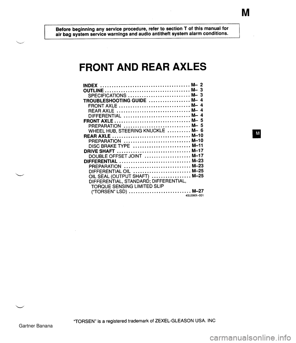
Before beginning any service procedure. refer to section T of this manual for air bag system service warnings and audio antitheft system alarm conditions . FRONT AND REAR AXLES ....................................... INDEX M- 2 ..................................... OUTLINE M- 3 SPECIFICATIONS ........................... M- 3 TROUBLESHOOTING GUIDE .................. M- 4 ............................... FRONT AXLE M- 4 ................................ REAR AXLE M- 4 ............................. DIFFERENTIAL M- 4 ................................. FRONT AXLE M- 5 PREPARATION ............................. M- 5 WHEEL HUB. STEERING KNUCKLE .......... M- 6 .................................. REAR AXLE M-10 PREPARATION ............................. M-10 ......................... DISC BRAKE TYPE M-11 ................................ DRIVE SHAFT M-17 .................... DOUBLE OFFSET JOINT M-17 ............................... DIFFERENTIAL M-23 PREPARATION ............................. M-23 DIFFERENTIAL OIL ......................... M-25 ................. OIL SEAL (OUTPUT SHAFT) M-25 DIFFERENTIAL. STANDARD; DIFFERENTIAL. TORQUE SENSING LIMITED SLIP ("TORSEN" LSD) ........................... M-27 45UOMX-001 "TORSEN" is a registered trademark of ZEXEL-GLEASON USA . INC Gartner Banana
Page 588 of 1708

OUTLINE OUTLINE Front axle Rear axle Differentlal Drive shaft Item I Specifications TY pe Bearing Double-wishbone Angular ball bearing Maximum wheel bearing play mm {in} TY pe Bearing 0.05 {0.002} Double-wishbone Angular ball bearing Maximum wheel bearing play mm {in} Type Reduction gear Reduction ratio Oil I Viscosity 0.05 {0.002} -- ---- Differential gear Ring gear size mm {in} Grade Above -1 8°C {O°F}: SAE 90 Below -1 8°C {O°F}: SAE 80 Standard Hypoid gear Straight-bevel gear 182.88 {7.20) API service GL-5 I Capacity L {US qt. imp qt} I 1 .OO {I .06,0.88) "TORSEN" LSD Worm gear 4.100 TY ~e Length mm {in} Constant velocity (double offset) joint 640.6 I25.220) 45UOMX-00 Gartner Banana
Page 631 of 1708

N OUTLINEIMANUAL STEERING OUTLINE SPECIFICATIONS Steering wheel Steering shaft and joint d Type Steering gear Outer diameter mm {in) I 370 {I 4.6) I Manual steering Power steering Lock-to-lock turns Shaft ~oinr Power assist 3.36 2-cross joint - I Engine speed sensing Gear Gear ratio 2.8 Rack-and-pinion m (infinite) Rack stroke mm {in} Power steering fluid MANUAL STEERING Collapsible, non-tilt 121 .O i4.76) - I ATF DexronBII or M-111 ~luidca~acit~ L~S qt, Imp qt) I - PREPARATION SST 0.8 (0.85, 0.70) Preload attachment 25UONX-003 Hexagon wrench 49 GO30 797 Handle For removal of tie-rod end 49 1243 785 Installer, boot For measurement of pinion torque For installation of bushing 49 0208 701 A Boot air out tool - For removal and installation of adjusting cover For installation of tie-rod end boot 49 DO32 31 6 Protractor For removal of oil seal For tightening of adjusting cover Gartner Banana
Page 730 of 1708

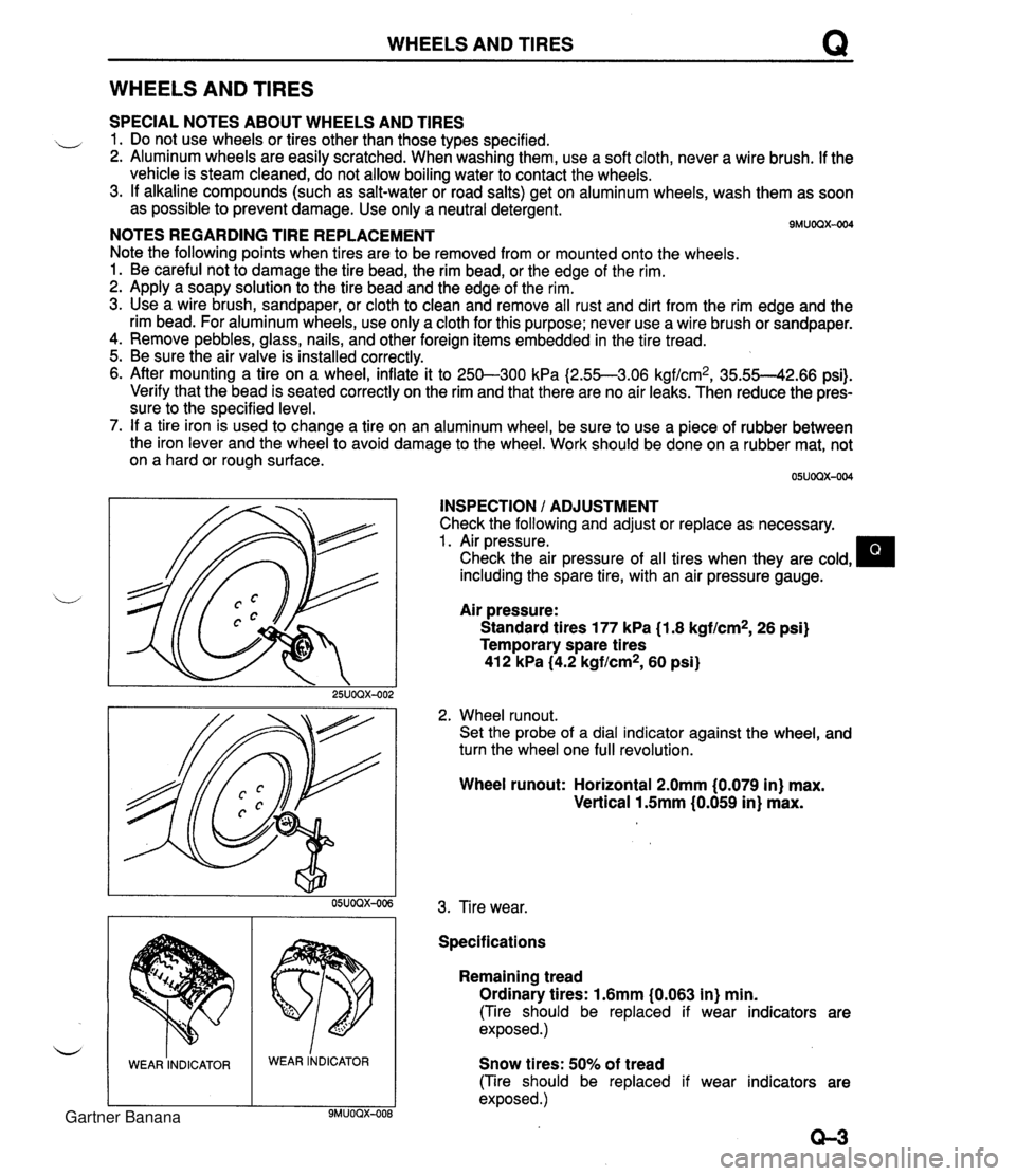
WHEELS AND TIRES Q WHEELS AND TIRES SPECIAL NOTES ABOUT WHEELS AND TIRES ,, 1. Do not use wheels or tires other than those types specified. 2. Aluminum wheels are easily scratched. When washing them, use a soft cloth, never a wire brush. If the vehicle is steam cleaned, do not allow boiling water to contact the wheels. 3. If alkaline compounds (such as salt-water or road salts) get on aluminum wheels, wash them as soon as possible to prevent damage. Use only a neutral detergent. - - 9MUOQX-004 NOTES REGARDING TIRE REPLACEMENT Note the following points when tires are to be removed from or mounted onto the wheels. 1. Be careful not to damage the tire bead, the rim bead, or the edge of the rim. 2. Apply a soapy solution to the tire bead and the edge of the rim. 3. Use a wire brush, sandpaper, or cloth to clean and remove all rust and dirt from the rim edge and the rim bead. For aluminum wheels, use only a cloth for this purpose; never use a wire brush or sandpaper. 4. Remove pebbles, glass, nails, and other foreign items embedded in the tire tread. 5. Be sure the air valve is installed correctly. 6. After mounting a tire on a wheel, inflate it to 250-300 kPa I2.55--3.06 kgf/cm2, 35.55--42.66 psi). Verify that the bead is seated correctly on the rim and that there are no air leaks. Then reduce the pres- sure to the specified level. 7. If a tire iron is used to change a tire on an aluminum wheel, be sure to use a piece of rubber between the iron lever and the wheel to avoid damage to the wheel. Work should be done on a rubber mat, not on a hard or rough surface. INSPECTION / ADJUSTMENT Check the following and adjust or replace as necessary. 1. Air pressure. Check the air pressure of all tires when they are cold, including the spare tire, with an air pressure gauge. u Air pressure: Standard tires 177 kPa (1.8 kgf/cm2, 26 psi) Temporary spare tires 412 kPa (4.2 kgf/cm2, 60 psi) 2. Wheel runout. Set the probe of a dial indicator against the wheel, and turn the wheel one full revolution. WEAR INDICATOR Wheel runout: Horizontal 2.0mm (0.079 in) max. Vertical 1.5mm (0.059 in) max. WEAR lNDICAToR 3. Tire wear. Specifications Remaining tread Ordinary tires: 1.6mm (0.063 in) min. (Tire should be replaced if wear indicators are exposed.) Snow tires: 50% of tread (Tire should be replaced if wear indicators are exposed .) Gartner Banana
Page 736 of 1708

OUTLINE OUTLINE SPECIFICATIONS Front Suspension - Transmission item (Stabilizer Specifications MT I AT - I Susoension tvoe I . , . , I . , Shock absorber Cylindrical double acting, low-pressure-gas charged I Double-wishbone TY pe Torsion bar Coil spring I - Diameter mm linl I 20.0 10.79) Identification mark color 19.0 (0.75) White Wire diameter mm (in) Coil inner diameter mm {in) I Blue Free length mm {in) Coil number 11 .O (0.43) 83 i3.27) 11 .O (0.43) 83 (3.27) 292.5 (1 1 32) 6.32 3 +. 3 (0.12 + 0.12) 0°18' + 18' Total toe-in I - I 35UORX-001 Rear Suspension 302.0 (1 1.89) 6.32 mm {in) degree Total toe-in (per side) 1 degree Front wheel alignment (Unladedt1) 0°09' +. 09' Caster anglee3 4"26' +. 45' Kingpin angle 11 "20' Maximum steering angle Transmission Specifications MT I AT Item Differential - Suspension type Inner Outer "TORSEN" LSD 1 Standard Double-wishbone Coil springs 370 23' a 2" 32" 32' -t 2" Camber anglee2 Torsion bar 12.0 (0.47) 1 11.0 (0.43) 1 11 .O (0.43) Cylindrical double acting, low-pressure-gas charged - Stabilizer Identification mark color Wire diameter mm {in) 0°24' + 45' Type Diameter mm {in) I Coil number I 7.68 I 7.96 I Shock absorber Yellow 10.1 {0.40} Coil inner diameter mm {in) Free length mm {in) Green 10.2 {0.40) 35UORX-002 *I Fuel tank full; radiator coolant and engine oil at specified levels; spare tire, jack, and tools in designated positions. '2 Difference between left and right must not exceed I O. '3 Difference between left and right must not exceed 1'30'. "TORSEN" is a registered trademark of ZEXEL-GLEASON USA.INC 83 I3.27) 348.5 j13.72) Rear wheel alignment (Unladed*') 83 (3.27) 356.5 (1 4.04) Total toe-in Total toe-in (per side) mm (in) degree degree 3 -c 3 (0.12 + 0.121 0°18' + 18' 0°09' + 09' Camber angle*2 -0°43' 2 30' Gartner Banana