MAZDA MX-5 1994 Workshop Manual
Manufacturer: MAZDA, Model Year: 1994, Model line: MX-5, Model: MAZDA MX-5 1994Pages: 1708, PDF Size: 82.34 MB
Page 221 of 1708

TROUBLESHOOTING GUIDE INSPECTION Check if PCME terminal voltages are OK (20,2N, 20,2P, 2Q, 2R, 2U and 2V) page F-146 Check if fuel cut operation is OK during decelera- tion Fuel cut: Above 1,900 rpm after warm-up Check for correct ignition timing at idle page F-76 Ignition timing: 10" 2 lo BTDC Check for correct fuel line pressure at idle page 6118 Fuel line pressure: 216-264 kPa i2.2-2.7 kgf/cm2, 32-48 psi) INSTALL CLAPS ' Run engine at idle and check if fuel line pressure is held after ignition switch turned OFF page F-109 Fuel line pressure: More than 147 kPa {I .5 kgf/cm2, 21 psi) for 5 mln. PRESSURE IGNITION 5 MIN. TIME SWITCH OFF Yes - No Yes No Yes No Yes No - Yes No ACTION Go to next step Check for cause (Refer to "Check Point for Each Terrni- nal") paae F-148 Go to next step Try known good PCME @ page F-144 Go to next step Adjust page M6 Go to next step High pressure Check if vacuum hose to pressure regulator is damaged or poorly connected o If OK, replace pressure regulator * page F-119 O If not OK, repair or replace hose So to next step Check fuel injector for fuel leakage page F-120 Change fuel to another brand Gartner Banana
Page 222 of 1708
![MAZDA MX-5 1994 Workshop Manual TROUBLESHOOTING GUIDE IT- MIL ALWAYS ON I ( DESCRIPTION I Self-Diagnosis Checker does not indicate Diagnostic Trouble Code No. but MIL always ON I I - - [TROUBLESHOOTING HINTS] Short circuit in wiring MAZDA MX-5 1994 Workshop Manual TROUBLESHOOTING GUIDE IT- MIL ALWAYS ON I ( DESCRIPTION I Self-Diagnosis Checker does not indicate Diagnostic Trouble Code No. but MIL always ON I I - - [TROUBLESHOOTING HINTS] Short circuit in wiring](/img/28/57072/w960_57072-221.png)
TROUBLESHOOTING GUIDE IT- MIL ALWAYS ON I ( DESCRIPTION I Self-Diagnosis Checker does not indicate Diagnostic Trouble Code No. but MIL always ON I I - - [TROUBLESHOOTING HINTS] Short circuit in wiring harness PCME malfunction ISTEP l INSPECTION I ACTION I 1 STEP 33 Disconnect (1 E) wire from PCME and check if MIL goes off 1 E MIL NEVER ON Ground (1 E) wire at PCME with jumper wire and check if MIL comes on 1 E Self-Diagnosis Checker indicates Diagnostic Trouble Code No. of input device but MIL never ON DEscR~pT~O~ I : Other indicator and warning lamps OK [TROUBLESHOOTING HINTS] Bulb burned out Open circuit in wiring harness PCME malfunction INSPECTION Yes No ACTION c3 If OK, replace PCME page F-143 I Q If not OK, repair PCME connector Replace PCME page F-143 Check for short circuit in wiring between combination me- ter and PCME page F-7 Yes No Check if bulb is OK I I Check connection condition of PCME connector tw page F-144 I r> If OK, repair (1 E) wire between PCME and combination meter as= page F-7 c3 If not OK, replace bulb Section T Gartner Banana
Page 223 of 1708
![MAZDA MX-5 1994 Workshop Manual F TROUBLESHOOTING GUIDE DESCRIPTION I Blower fan operates but cool air not expelled ITROUBLESHOOTING HINTS] Open or short circuit in wiring harness NC relay malfunction 34 Air conditioning sensor malf MAZDA MX-5 1994 Workshop Manual F TROUBLESHOOTING GUIDE DESCRIPTION I Blower fan operates but cool air not expelled ITROUBLESHOOTING HINTS] Open or short circuit in wiring harness NC relay malfunction 34 Air conditioning sensor malf](/img/28/57072/w960_57072-222.png)
F TROUBLESHOOTING GUIDE DESCRIPTION I Blower fan operates but cool air not expelled ITROUBLESHOOTING HINTS] Open or short circuit in wiring harness NC relay malfunction 34 Air conditioning sensor malfunction Magnetic clutch malfunction PCME malfunction AIC DOES NOT WORK INSPECTION ;round terminal B at NC relay with jumper wire Yes tnd check if condenser fan operates when ignition ;witch is turned ON #C RELAY I ;round terminal B at PCME 1 J terminal with jump- Yes ,r wire and check if condenser fan operates when gnition switch is turned ON - No :heck if Air conditioning sensor is OK Yes Section U ACTION 30 to next step 30 to A/C system Troubleshooting Section U 30 to next step qepair wire between PCME and A/C relay page F-7 Try known good PCME page F-144 ;heck Air conditioning sensor and wiring Section U Gartner Banana
Page 224 of 1708

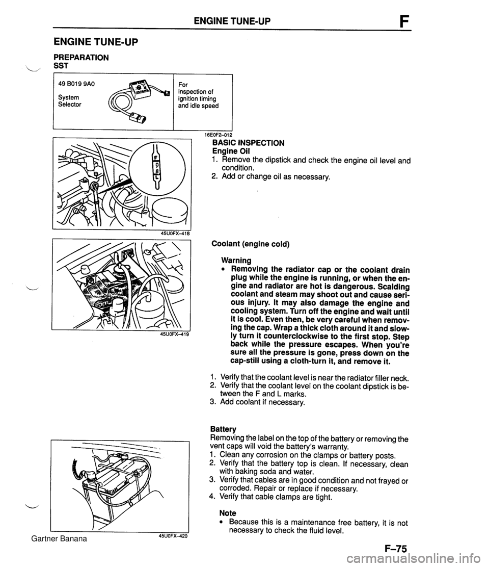
ENGINE TUNE-UP ENGINE TUNE-UP PREPARATION L" SST r I I 16EOF2-012 BASIC INSPECTION Engine Oil 1. Remove the dipstick and check the engine oil level and condition. 2. Add or change oil as necessary. 49 B019 9AO System Selector Coolant (engine cold) For inspection of ignition timing and idle speed Warning Removing the radiator cap or the coolant drain plug while the engine is running, or when the en- gine and radiator are hot is dangerous. Scalding coolant and steam may shoot out and cause seri- ous injury. It may also damage the engine and cooling system. Turn off the engine and wait until it is cool. Even then, be very careful when remov- ing the cap. Wrap a thick cloth around it and slow- ly turn it counterclockwise to the first stop. Step back while the pressure escapes. When you're sure all the pressure is gone, press down on the cap-still using a cloth-turn it, and remove it. 1. Verify that the coolant level is near the radiator filler neck. 2. Verify that the coolant level on the coolant dipstick is be- tween the F and L marks. 3. Add coolant if necessary. Battery Removing the label on the top of the battery or removing the vent caps will void the battery's warranty. 1. Clean any corrosion on the clamps or battery posts. 2. Verify that the battery top is clean. If necessary, clean with baking soda and water. 3. Verify that cables are in good condition and not frayed or corroded. Repair or replace if necessary. 4. Verify that cable clamps are tight. Note Because this is a maintenance free battery, it is not necessary to check the fluid level. Gartner Banana
Page 225 of 1708

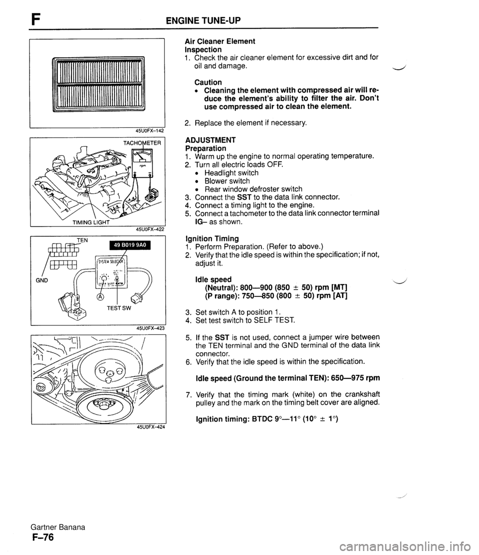
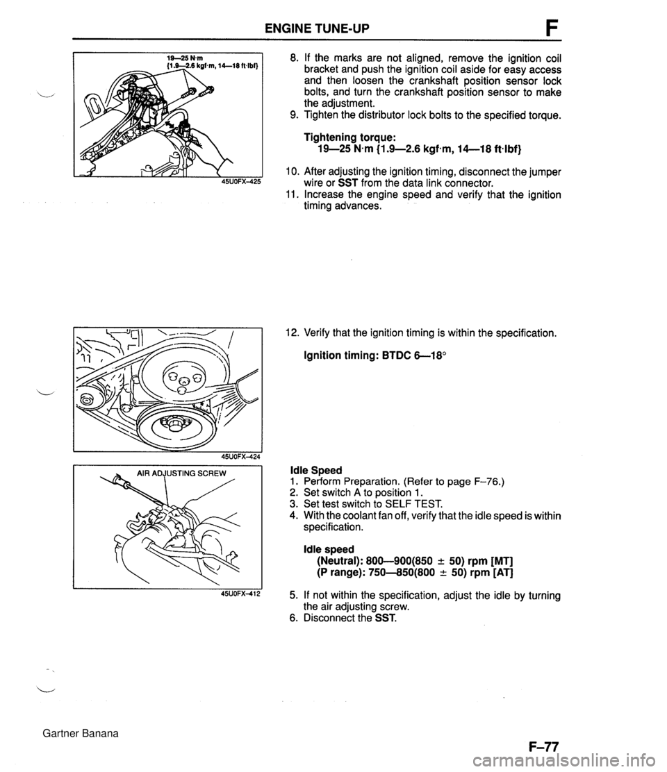
ENGINE TUNE-UP - TIMING LIGHT - 45UOFX422 GND Irnr Air Cleaner Element Inspection 1. Check the air cleaner element for excessive dirt and for oil and damage. Caution Cleaning the element with compressed air will re- duce the element's ability to filter the air. Don't use compressed air to clean the element. 2. Replace the element if necessary. ADJUSTMENT Preparation 1. Warm up the engine to normal operating temperature. 2. Turn all electric loads OFF. Headlight switch Blower switch Rear window defroster switch 3. Connect the SST to the data link connector. 4. Connect a timing light to the engine. 5. Connect a tachometer to the data link connector terminal IG- as shown. Ignition Timing 1. Perform Preparation. (Refer to above.) 2. Verify that the idle speed is within the specification; if not, adjust it. Idle speed 4 (Neutral): 800-900 (850 + 50) rpm [MT] (P range): 750-850 (800 & 50) rpm [AT] 3. Set switch A to position 1. 4. Set test switch to SELF TEST. 5. If the SST is not used, connect a jumper wire between the TEN terminal and the GND terminal of the data link connector. 6. Verify that the idle speed is within the specification. ldle speed (Ground the terminal TEN): 650-975 rpm 7. Verify that the timing mark (white) on the crankshaft pulley and the mark on the timing belt cover are aligned. lgnition timing: BTDC 9"-11" (10" & lo) Gartner Banana
Page 226 of 1708

ENGINE TUNE-UP 8. If the marks are not aligned, remove the ignition coil bracket and push the ignition coil aside for easy access and then loosen the crankshaft position sensor lock bolts, and turn the crankshaft position sensor to make the adjustment. 9. Tighten the distributor lock bolts to the specified torque. Tightening torque: 19-25 N-m (1.9-2.6 kgfem, 14--18 ftqlbf) 10. After adjusting the ignition timing, disconnect the jumper wire or SST from the data link connector. 11. Increase the engine speed and verify that the ignition timing advances. 12. Verify that the ignition timing is within the specification. Ignition timing: BTDC 6-18' ldle Speed 1. Perform Preparation. (Refer to page F-76.) 2. Set switch A to position 1. 3. Set test switch to SELF TEST. 4. With the coolant fan off, verify that the idle speed is within specification. ldle speed (Neutral): 800-900(850 + 50) rpm [MT] (P range): 750--850(800 -c 50) rpm [AT] 5. If not within the specification, adjust the idle by turning the air adjusting screw. 6. Disconnect the SST. Gartner Banana
Page 227 of 1708

ON-BOARD DIAGNOSIS SYSTEM ON-BOARD DIAGNOSIS SYSTEM DESCRIPTION When troubles occur in the main input devices or output devices, check for the cause using the SST. Q Failures of each input and output device are indicated and retrieved from the powertrain control module (engine) as diagnosis trouble code numbers. Note For input devices, the PCME continuously checks for malfunctions. For output devices, it checks for malfunctions only in a three-second period after the ignition switch is turned to ON, or the TEN termi- nal of the data link connector is grounded. - INPUT SIGNALS POWERTRAIN CONTROL MODULE (ENGINE) I- -t INPUT DEVICES FAIL-SAFE FUNCTION . ON-BOARD ,, DIAGNOSIS -+ SYSTEM - - 1 I I MALFUNCTIQN DISPLAY FUNCTION -t b P v C-- MONITOR FUNCTION u SYSTEM SELF-DIAGNOSIS SELECTOR CHECKER I CHECK Gartner Banana
Page 228 of 1708

ON-BOARD DIAGNOSIS SYSTEM PREPARATION SST 1 SELECT SW A STEM SELECT 1 * SYSTEM SEUC . TEST SW - SYSTEM SELECT i # SELF TEST DIAGNOSTIC TROUBLE CODE NUMBER Inspection procedure 1. Connect the SSTs to the data link connector and a ground. 2. Set the select switch to position A. 49 B019 9AO System Selector 3. Set the System Selector to position 1 and SELF TEST as shown. For diagnosis 4. Turn the ignition switch ON. 5. Verify that 88 flashes on the digital display and that the buzzer sounds for 3 sec. after turning the ignition switch ON. 6. If 88 does not flash, check the main relay (Refer to page F-156.), power supply circuit, and check connector wir- mg. 7. If 88 flashes and the buzzer continues for more than 20 sec., check for a short circuit between the powertrain control module (engine) terminal 1 E and the data link connector. Replace the powertrain control module (en- gine) if necessary and perform Steps 3 and 4 again. 8. Note any code numbers and check for the causes by re- ferring to the check sequences shown on pages F-83 to F-93. Repair as necessary. 9. After repairs, cancel the code numbers by performing the "After-repair procedure". (Refer to page F-94.) Gartner Banana
Page 229 of 1708

ON-BOARD DIAGNOSIS SYSTEM Principle of Code Cycle Diagnostic trouble codes are determined as shown below. 1. Code cycle break The time between diagnostic trouble code cycles is 4.0 seconds (the time the lamp is off). 1 CYCLE DIAGNOSTIC I I TROUBLE CODE, CYCLE BREAK I JUU I I C-----------l 4.0 SEC. 2. Second digit of diagnostic trouble code (ones position) The digit in the ones position of the diagnostic trouble code represents the number of times the buzzer sounds 0.4 second during one cycle. I 1 1 CYCLE DIAGNOSTIC DIAGNOSTIC ON TROUBLE CODE I TROUBLE 1 2 3 CYCLE BREAK CODE: 03 UICCl4 4.0 4.0 4.0 SEC. SEC. SEC. 3. First digit of diagnostic trouble code (tens position) The digit in the tens position of the diagnostic trouble code represents the number of times the buzzer is on 1.2 seconds during one cycle. It should also be noted that the light goes off for 1.6 seconds between the long and short pulses of the buzzer. r 1 CYCLE DIAGNOSTIC DIAGNOSTIC . TROUBLE CODE TROUBLE L 12 CODE: 22 - FIRST DIGIT SECOND DIGIT Gartner Banana
Page 230 of 1708

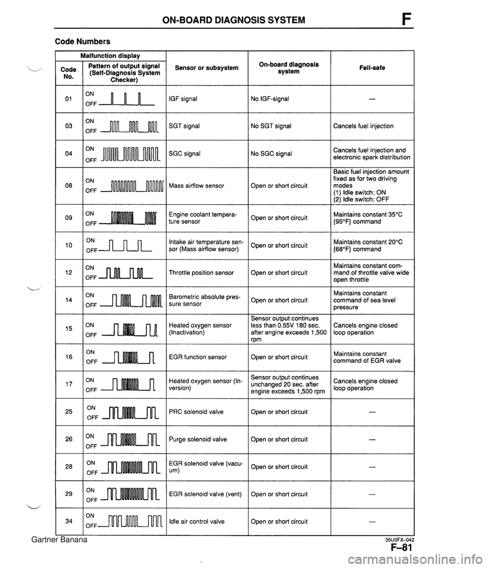
ON-BOARD DIAGNOSIS SYSTEM F Code Numbers Malfunction display On-board diagnosis system Code No. 0 1 03 Pattern of output signal (Self-Diagnosis System Checker) Sensor or subsystem IGF signal SGT signal Fail-safe ON OFF A-n-L ON OFF m No SGT signal ON OFF JuUu Cancels fuel injection No SGC signal Cancels fuel injection and electronic spark distribution SGC signal Basic fuel injection amount fixed as for two driving modes (1) ldle switch: ON (2) ldle switch: OFF ON OFF Mass airflow sensor Open or short circuit Engine coolant tempera- ture sensor ON OFF -JLnn Open or short circuit Intake air temperature sen- sor (Mass airflow sensor) Maintains constant 35°C {95"F} command Maintains constant 20°C {68"F} command Open or short circuit ON OFF -nNLnM- Maintains constant com- mand of throttle valve wide open throttle Throttle position sensor Open or short circuit ON OFF Barometric absolute pres- sure sensor Maintains constant command of sea level pressure Open or short circuit Heated oxygen sensor (Inactivation) EGR function sensor Sensor output continues less than 0.55V 180 sec. after engine exceeds 1,500 rpm Cancels engine closed loop operation ON OFF ON OFF --nMM.A ON OFF --rMMMA Open or short circuit Heated oxygen sensor (In- version) Maintains constant command of EGR valve ON OFF JlnMkm Sensor output continues unchanged 20 sec. after engine exceeds 1,500 rpm PRC solenoid valve Cancels engine closed loop operation Open or short circuit Open or short circuit I - ON OFF m Purge solenoid valve ON OFF EGR solenoid valve (vacu- um) ON OFF Open or short circuit EGR solenoid valve (vent) ldle air control valve - Open or short circuit ON OFF m Open or short circuit I - Gartner Banana