differential MAZDA MX-5 1994 Owner's Guide
[x] Cancel search | Manufacturer: MAZDA, Model Year: 1994, Model line: MX-5, Model: MAZDA MX-5 1994Pages: 1708, PDF Size: 82.34 MB
Page 615 of 1708

M DIFFERENTIAL Installation note Differential 1. Connect the drive shaft to the output shaft with the marks aligned. 2. Install the differential. - JOMX- Tightening torque 0: 83-98 N-m (8.5-10 kgf.m, 61-72 ft4bf) @I: 18-26 N.m (1.8-2.7 kgf.m, 13-20 ft.lbf) 3. Adjust the rear wheel alignment if the upper arm installa- tion bolt and nut were removed. (section R.) Power plant frame (PPF) 1. Install the differential mounting spacer. Tightening torque: 37-52 N-m (3.8-5.3 kgf.m, 27-38 ftdbf} .i 2. Support the transmission with a jack so that it is level. 3. Position the PPF and snugly tighten the transmission- side bolts by hand. 4. Verify that the sleeve is installed into the block. 5. Install the spacer and bolts and snugly tighten them. The reamer bolt should be installed in the forward hole. 6. Snugly install the power plant frame bracket. 7. Tighten the transmission-side bolts. Tightening torque: lO4--123 N.m (1 0.6-1 2.6 kgf.m, 77-91 ft4bf) Gartner Banana
Page 616 of 1708

DIFFERENTIAL M 8. Tighten the differential-side bolts. Tightening torque: lO4--123 N.m (1 0.6-1 2.6 kgf.m, 77-91 ft~lbf) 9. Install the power plant frame bracket. (Manual transmis- sion) Tightening torque 0: 104-123 N-m (10.6-12.6 kgf.m, 77-91 ftlbf) 0: 36-54 N.m I3.7--5.5 kgf-m, 2740 ft-lbf) 10. Remove the jack, and connect the wire harness. Gartner Banana
Page 617 of 1708

M DIFFERENTIAL Overhaul 1. Disassemble in the order shown in the figure, referring to Disassembly Note. 2. Inspect all parts and repair or replace as necessary. 3. Assemble in the reverse order of disassembly, referring to Assembly Note. f - Gartner Banana
Page 618 of 1708

DIFFERENTIAL M 1. Output shafts Disassembly Note .......... page M-34 Assembly Note ............ page M-42 u 2. Differential case Disassembly Note .......... page M-34 Assembly Note ............ page M-42 3. Differential gear assembly Disassembly Note .......... page M-34 4. Lock plates 5. Bearing caps Disassembly Note .......... page M-34 Assembly Note ............ page M-42 6. Adjusting nuts Disassembly Note .......... page M-34 7. Bearing outer races (Side bearing) 8. Gear case assembly ("TORSEN" LSD) 9. Ring gear lnspect individual gear teeth for wear and cracks 10. Knock pin (Standard) Disassembly Note .......... page M-34 11. Pinion shaft (Standard) 12. Pinion gears (Standard) lnspect individual gear teeth for wear and cracks 13. Thrust washers (Standard) 14. Side gears (Standard) lnspect individual gear teeth for wear and cracks b 15. Thrust washers (Standard) Assembly Note ............ page M-40 16. Bearing inner races (Side bearing) Disassembly Note .......... page M-34 lnspect for damage and rough rotation 17. Gear case 18. Locknut (Companion flange) Disassembly Note .......... page M-35 19. Washer 20. Companion flange Disassembly Note .......... page M-35 lnspect splines for wear and damage 21. Oil seal (Companion flange) 22. Washer 23. Drive pinion Disassembly Note .......... page M-35 lnspect splines for wear and damage lnspect individual gear teeth for wear and cracks 24. Spacer Assembly Note ............ page M-37 25. Bearing inner race (Front bearing) lnspect for damage and rough rotation ............ Assembly Note page M-38 26. Collapsible spacer 27. Bearing outer race (Rear bearing) Disassembly Note .......... page M-35 Assembly Note ............ page M-37 28. Bearing outer race (Front bearing) Disassembly Note .......... page M-35 Assembly Note ............ page M-36 29. Bearing inner race (Rear bearing) Disassembly Note .......... page M-35 lnspect for damage and rough rotation Assembly Note ............ page M-37 30. Differential carrier 31. Oil seal (Output shaft) Assembly Note ............ page M-36 32. Baffle 33. Breather 34. Differential mount Disassembly Note .......... page M-36 Assembly Note ............ page M-36 45UOMX-053 Gartner Banana
Page 619 of 1708

M DIFFERENTIAL Disassembly note Output shafts Remove the output shafts with two pry bars as shown in the figure. -J Differential case Caution The differential case is made of aluminum, and is therefore easily dented and scratched by metal tools. When. separating the differential carrier from the case, use only a plastic hammer at the point shown in the figure. Strike the differential carrier with a copper hammer to separate it from the case. Differential gear assembly Mount the differential gear assembly on the SST. Bearing caps Mark one bearing cap and the carrier. Adjusting nuts Mark one adjusting nuts and the carrier. Knock pin Secure the gear case in a vise and tap out the knock pin toward the ring gear side. Bearing inner races (Side bearing) Note Mark the bearings so that they can later be reinstalled in the same position. Remove the bearing inner races (side bearing) from the gear case by using the SST. -1 Gartner Banana
Page 620 of 1708

DIFFERENTIAL id Locknut (Companion flange) Hold the companion flange by using the SST and remove the locknut. Companion flange Pull the companion flange off by using the SST. Drive pinion Push out the drive pinion by attaching a miscellaneous locknut to the drive pinion, and tapping it with a copper hammer. Bearing outer races (Front, and rear bearing) Remove the bearing outer races using the two grooves in the carrier and alternately tapping the sides of the races. Bearing inner race (Rear bearing) While supporting the drive pinion to keep it from falling, remove the bearing inner race (rear bearing) by using the SST. Gartner Banana
Page 621 of 1708

M DIFFERENTIAL Differential mount 1. Drill holes around the differential mount. 2. Hit the edge of the differential mount to remove it. Assembly note Differential mounting rubber 1. Install the new differential mount with the voids facing front and rear. 2. Press in the differential mount by using the SST. Press force: 19600 N (2000 kgf, 4400 Ibf) Oil seal (Output shaft) Apply lithium based grease to the new oil seal lip and install it by using the SST. Bearing outer race (front bearing) Instdl the bearing outer race (front bearing) by using the SST. Gartner Banana
Page 622 of 1708

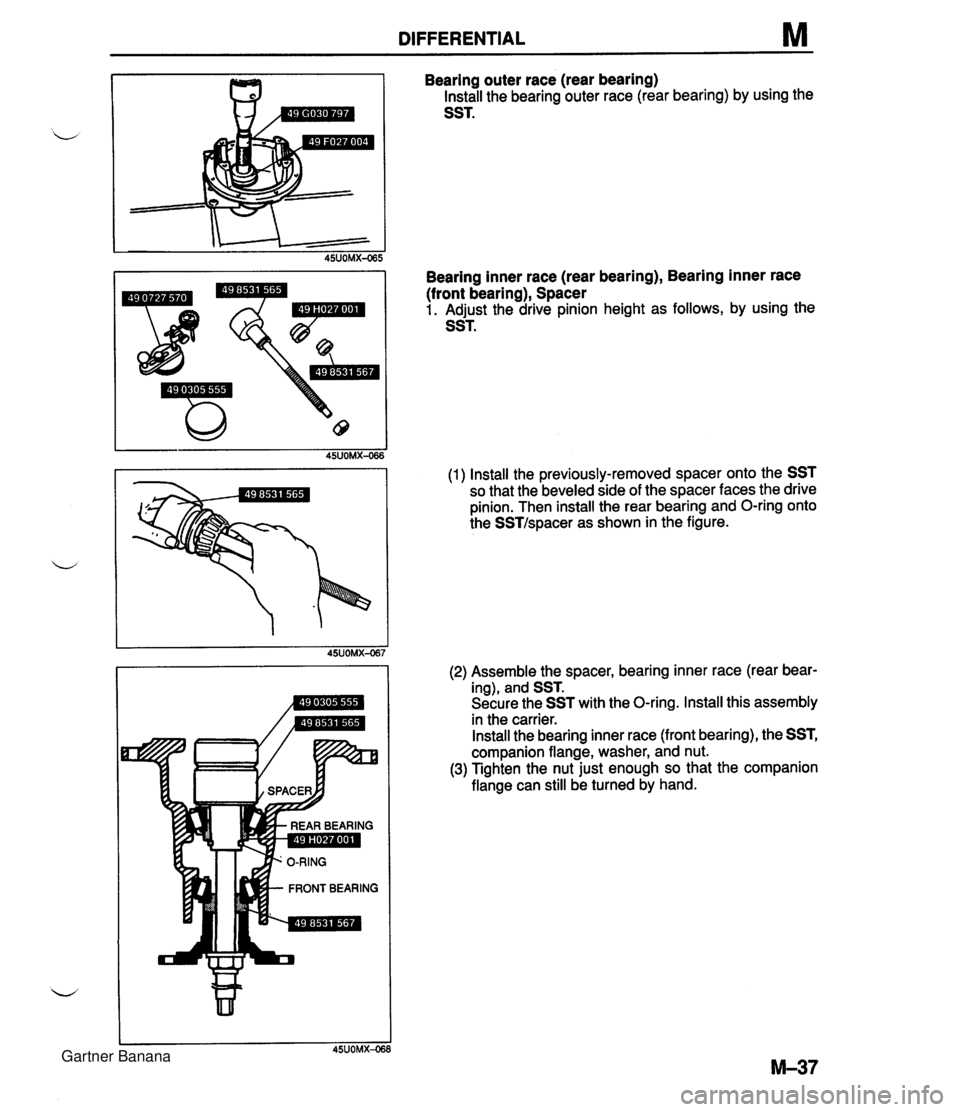
DIFFERENTIAL M Bearing outer race (rear bearing) Install the bearing outer race (rear bearing) by using the SST. Bearing inner race (rear bearing), Bearing inner race (front bearing), Spacer 1. Adjust the drive pinion height as follows, by using the SST. (1) Install the previously-removed spacer onto the SST so that the beveled side of the spacer faces the drive pinion. Then install the rear bearing and O-ring onto the SSTIspacer as shown in the figure. (2) Assemble the spacer, bearing inner race (rear bear- ing), and SST. Secure the SST with the O-ring. Install this assembly in the carrier. Install the bearing inner race (front bearing), the SST, companion flange, washer, and nut. (3) Tighten the nut just enough so that the companion flange can still be turned by hand. Gartner Banana
Page 623 of 1708

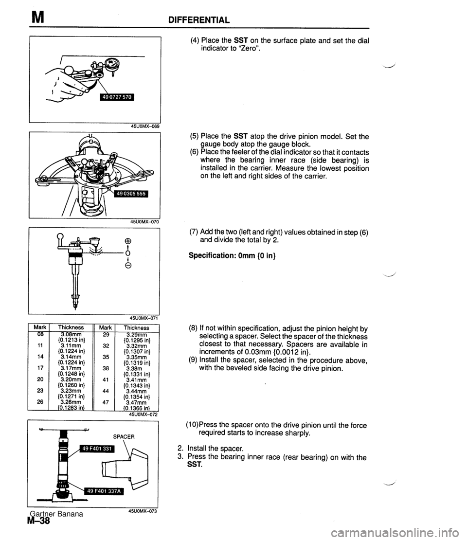
M DIFFERENTIAL (4) Place the SST on the surface plate and set the dial indicator to "Zero". (5) Place the SST atop the drive pinion model. Set the gauge body atop the gauge block. (6) Place the feeler of the dial indicator so that it contacts where the bearing inner race (side bearing) is installed in the carrier. Measure the lowest position on the left and right sides of the carrier. (7) Add the two (left and right) values obtained in step (6) and divide the total by 2. Specification: Omm (0 in) Thickness mm {tP2"13 in} 3.11mm (0.1 224 in} 3.14mm (0.1 224 in} 3.1 7mm (0. I248 in} 3.20mm (0.1260 in} 3.23mm (0.1271 in] 3.26mm 40.1283 in} Thickness rnm {t&5 in} 3.32mm (0.1307 in} 3.35mm (0.1319 in] 3.38m (0.1331 in) 3.41 mm (0.1343 in) 3.44mm {0.1354 in) 3.47rnm (0.1366 in) 45UOMX-47: (8) If not within specification, adjust the pinion height by selecting a spacer. Select the spacer of the thickness closest to that necessary. Spacers are available in increments of 0.03mm (0.001 2 in). (9) Install the spacer, selected in the procedure above, with the beveled side facing the drive pinion. (1 0)Press the spacer onto the drive pinion until the force SPACER required starts to increase sharply. 2. Install the sDacer. 3. Press the bearing inner race (rear bearing) on with the SST. Gartner Banana
Page 624 of 1708

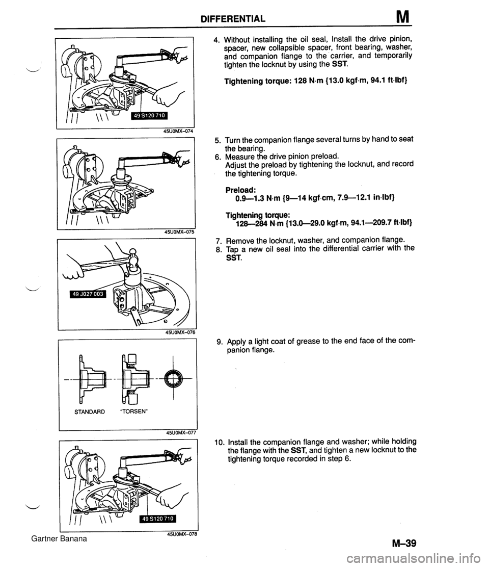
DIFFERENTIAL M 4. Without installing the oil seal, Install the drive pinion, spacer, new collapsible spacer, front bearing, washer, and companion flange to the carrier, and temporarily tighten the locknut by using the SST. Tightening torque: 128 N-m (13.0 kgf-m, 94.1 ft-lbf) 5. Turn the companion flange several turns by hand to seat the bearing. 6. Measure the drive pinion preload. Adjust the preload by tightening the locknut, and record the tightening torque. STANDARD "TORSEN" 45UOMX-07; Preload: 0.9-1.3 N.m (9-1 4 kgf.cm, 7.9-1 2.1 in4bf) Tightening torque: 128-284 N.m (13.0-29.0 kgf.m, 94.1-209.7 ft-lbf) 7. Remove the locknut, washer, and companion flange. 8. T~D a new oil seal into the differential carrier with the 9. Apply a light coat of grease to the end face of the com- panion flange. 10. Install the companion flange and washer; while holding the flange with the SST, and tighten a new locknut to the tightening torque recorded in step 6. Gartner Banana