differential MAZDA MX-5 1994 Service Manual
[x] Cancel search | Manufacturer: MAZDA, Model Year: 1994, Model line: MX-5, Model: MAZDA MX-5 1994Pages: 1708, PDF Size: 82.34 MB
Page 625 of 1708

M DIFFERENTIAL Thrust washers (Standard) 1. Adjust the backlash of the side gears and pinion gear as follows. (Standard) (1) Set a dial gauge against the pinion gear as shown. ,+, (2) Secure one of the side gears. (3) Move the pinion gear, and measure the backlash at the end of it. If not within specification, replace the dif- ferential gear as an assembly. ("TORSEN" LSD) Standard backlash: 04.1 mm (0-0.004 in) (4) If the backlash exceeds the standard, use the select- able thrust washers for adjustment. 2. Install the new knock pin to secure the pinion shaft. Stake the pin with a punch to prevent it from coming out of the case. Thrust washer thickness: 3. Apply thread-locking compound to bolt threads @ and points @I of the gear back face. Apply approximately 0.04 cm3 I0.04 cc, 0.0024 cu in} of thread-locking com- pound at each point and bolt thread. 4. lnstall the ring gear onto the gear case. Identification mark 0 0.5 1 1.5 2 Tightening torque: 69-83 N.m (7.0--8.5 kgf-m, 51-61 ft-lbf) Thickness 2.00mm i0.0787 in} 2.05mm (0.0807 in) 2.10mm {0.0827 in) 2.15mm (0.0846 in} 2.20mm i0.0866 in} 5. Press the bearing inner races (side bearing) on by using the SST. 6. Install the differential gear assembly in the carrier. 7. Note the identification marks on the adjusting nuts, and install them on their respective sides. 8. lnstall the differential bearing caps, making sure that the identification mark on the cap corresponds with the one on the carrier by using the SST. Then temporarily tighten the bolts. Gartner Banana
Page 626 of 1708

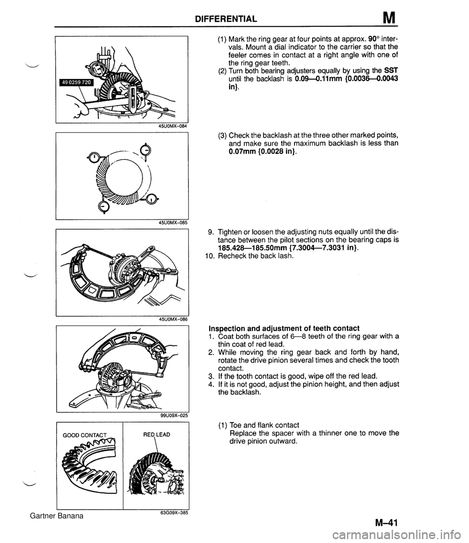
DIFFERENTIAL M (1) Mark the ring gear at four points at approx. 90" inter- vals. Mount a dial indicator to the carrier so that the feeler comes in contact at a right angle with one of the ring gear teeth. (2) Turn both bearing adjusters equally by using the SST until the backlash is 0.09-0.11mm {0.0036-€).0043 in). (3) Check the backlash at the three other marked points, and make sure the maximum backlash is less than 0.07mm (0.0028 in). 9. Tighten or loosen the adjusting nuts equally until the dis- tance between the pilot sections on the bearing caps is 185.428-1 85SOmm (7.3004--7.3031 in). 10. Recheck the back lash. Inspection and adjustment of teeth contact 1. Coat both surfaces of 6-8 teeth of the ring gear with a thin coat of red lead. 2. While moving the ring gear back and forth by hand, rotate the drive pinion several times and check the tooth contact. 3. If the tooth contact is good, wipe off the red lead. 4. If it is not good, adjust the pinion height, and then adjust the backlash. (1) Toe and flank contact Replace the spacer with a thinner one to move the drive pinion outward. Gartner Banana
Page 627 of 1708

M DIFFERENTIAL I HEEL CONTACT FACE CONTACT I (2) Heel and face contact Replace the spacer with a thicker one to bring the drive pinion in. d Bearing caps 1. Tighten the bearing cap bolts. Tightening torque: 37-52 N-m {3.8-5.3 kgf-m, 27-38 ft4bf) 2. Install the lock plates on the bearing caps. Tightening torque: 18-25 N.m (1.8-2.6 kgf-m, 13-19 ft.lbf) Differential case 1. Apply sealant to the housing face. 2. Tighten the bolts. Tightening torque: 23-26 N.m (2.3-2.7 kgf.m, 17-20 ft.lbf) Output shaft 1. Install a new clip. 2. Install the output shafts into the side gears by lightly tap- ping them with a plastic hammer. 3. Verify that the output shafts are hooked into the side gears by pulling them by hand. Gartner Banana
Page 736 of 1708

OUTLINE OUTLINE SPECIFICATIONS Front Suspension - Transmission item (Stabilizer Specifications MT I AT - I Susoension tvoe I . , . , I . , Shock absorber Cylindrical double acting, low-pressure-gas charged I Double-wishbone TY pe Torsion bar Coil spring I - Diameter mm linl I 20.0 10.79) Identification mark color 19.0 (0.75) White Wire diameter mm (in) Coil inner diameter mm {in) I Blue Free length mm {in) Coil number 11 .O (0.43) 83 i3.27) 11 .O (0.43) 83 (3.27) 292.5 (1 1 32) 6.32 3 +. 3 (0.12 + 0.12) 0°18' + 18' Total toe-in I - I 35UORX-001 Rear Suspension 302.0 (1 1.89) 6.32 mm {in) degree Total toe-in (per side) 1 degree Front wheel alignment (Unladedt1) 0°09' +. 09' Caster anglee3 4"26' +. 45' Kingpin angle 11 "20' Maximum steering angle Transmission Specifications MT I AT Item Differential - Suspension type Inner Outer "TORSEN" LSD 1 Standard Double-wishbone Coil springs 370 23' a 2" 32" 32' -t 2" Camber anglee2 Torsion bar 12.0 (0.47) 1 11.0 (0.43) 1 11 .O (0.43) Cylindrical double acting, low-pressure-gas charged - Stabilizer Identification mark color Wire diameter mm {in) 0°24' + 45' Type Diameter mm {in) I Coil number I 7.68 I 7.96 I Shock absorber Yellow 10.1 {0.40} Coil inner diameter mm {in) Free length mm {in) Green 10.2 {0.40) 35UORX-002 *I Fuel tank full; radiator coolant and engine oil at specified levels; spare tire, jack, and tools in designated positions. '2 Difference between left and right must not exceed I O. '3 Difference between left and right must not exceed 1'30'. "TORSEN" is a registered trademark of ZEXEL-GLEASON USA.INC 83 I3.27) 348.5 j13.72) Rear wheel alignment (Unladed*') 83 (3.27) 356.5 (1 4.04) Total toe-in Total toe-in (per side) mm (in) degree degree 3 -c 3 (0.12 + 0.121 0°18' + 18' 0°09' + 09' Camber angle*2 -0°43' 2 30' Gartner Banana
Page 758 of 1708

R REAR SUSPENSION (DOUBLE-WISHBONE) CROSSMEMBER Removal I Inspection I Installation 1. Jack up the vehicle and support it with safety stands. 2. Remove the wheels and tires. d 3. Remove the differential and the power plant frame. (Refer to section M.) 4. Lower the crossmember and other suspension parts as an assembly, and then separate the parts. 5. Remove in the order shown in the figure. 6. lnspect parts and repair or replace as necessary. 7. Install in the reverse order of removal. 8. Loosely tighten the stabilizer bracket, upper arm, and lower arm bolts. Tighten all other nuts and bolts to the specified torques. 9. Lower the vehicle. 10. With the vehicle unloaded, tighten the stabilizer bracket, upper arm, and lower arm bolts to the specified torques. 11. Adjust the rear wheel alignment. (Refer to page R-9.) 12. Bleed the air from the brake system. (Refer to section P.) 13. Adjust the parking brake lever stroke. (Refer to section P.) 1. Differential mounting pipe 6. Shock absorber bolt 2. Parking brake cable 7. Stabilizer bracket Removal / Installation . . . . . . . . . Section P 8. Upper arm bolt 3. Brake pipe 9. Adjusting cam bolt Removal / Installation . . . . . . . . . Section P 10. Rear crossmember assembly 4. Brake pipe joint Inspect for damage 5. Battery cable bracket Gartner Banana
Page 1113 of 1708

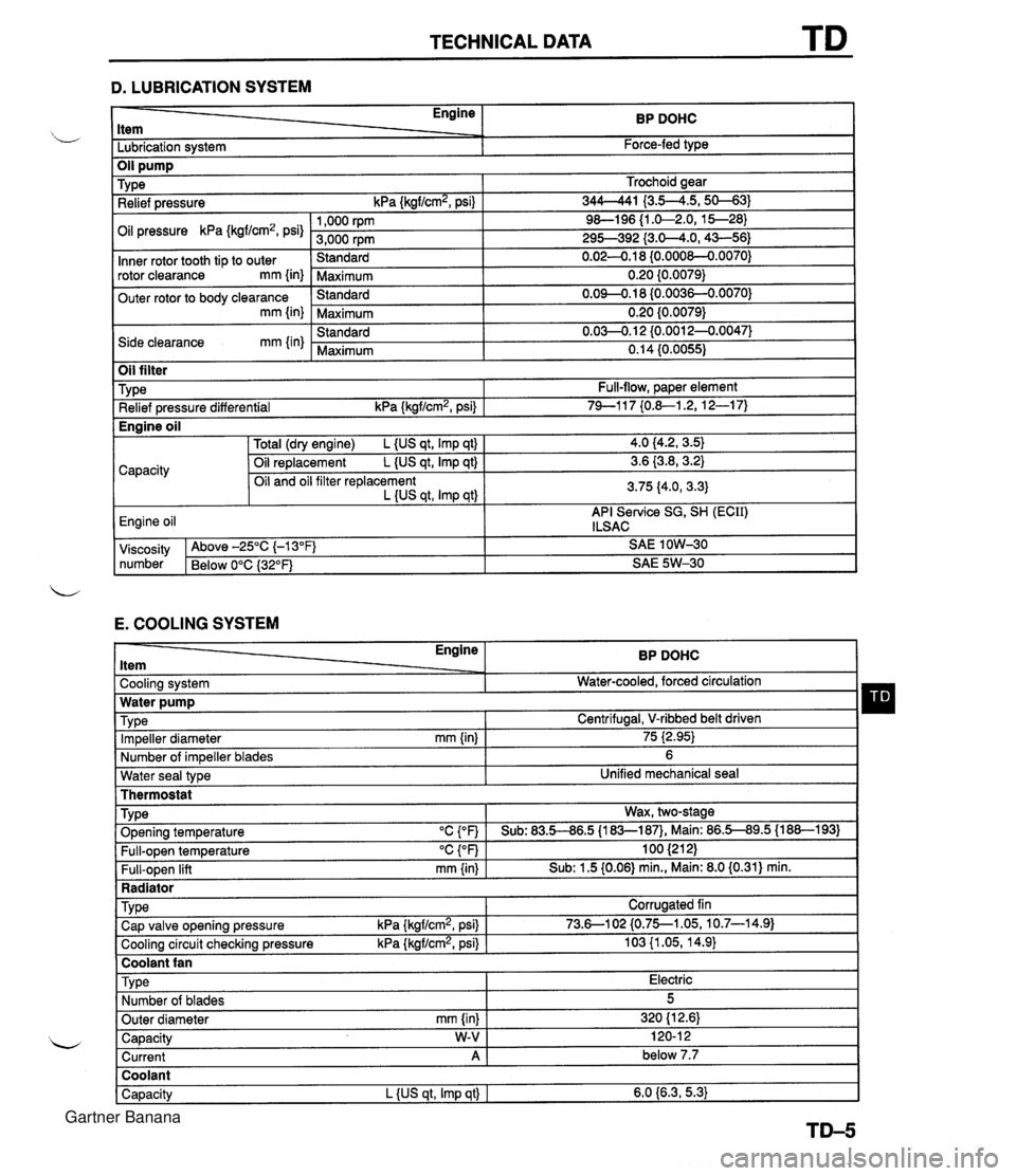
TECHNICAL DATA D. LUBRICATION SYSTEM - Engine ltem BP DOHC - -. Lubrication system Force-fed type E. COOLING SYSTEM Trochoid gear 344-41 I3.5--4.5,s-31 9&l96 {I .&2.0, 15--28) 295-392 {3.0-4.0,43-56) 0.02-0.1 8 {0.000&0.0070) 0.20 {0.0079) 0.09-0.18 (0.0036-0.0070) 0.20 {0.0079) 0.03-0.1 2 {0.0012-0.0047) 0.14 (0.0055) TY pe Relief pressure kPa {kgf/cm2, psi) Oil pressure kPa {kgf/cm2, psi) Inner rotor tooth tip to outer rotor clearance mm {in) Outer rotor to body clearance mm {in) Side clearance mm {in) Water seal type I Unified mechanical seal Thermostat 1,000 rpm 3,000 rpm Standard Maximum Standard Maximum Standard Maximum Oil filter Engine ltem - - Cooling system . . Impeller diameter mm {in) Number of impeller blades Type Relief pressure differential kPa {kgf/cm2, psi) BP DOHC Water-cooled, forced circulation - 75 i2.95) 6 Full-flow, paper element 74-1 17 {0.&1.2, 12-1 7) TY pe . ., . . . - Radiator I Water pump Wax, two-stage v. . . Full-open temperature "c {OF) Full-open lift mm {in) Engine oil TVD~ O~enina tem~erature "C con I Sub: 83.5-86.5 U83-187). Main: 86.5-89.5 (1 88-1 931 100 (21 2) Sub: 1.5 (0.06) min., Main: 8.0 (0.31) min. -. . - . . Cooling circuit checking pressure kPa {kgflcmz, psi) I 103 {I .05, 14.9) I Centrifugal, V-ribbed belt driven TY pe I Coolant fan I 4.0 (4.2, 3.5) 3.6 {3.8,3.2) 3.75 (4.0, 3.3) API Service SG, SH (ECII) ILSAC Capacity Corrugated fin viscosity Above -25°C (-1 3°F) SAE 1 OW-30 number Below 0°C {3Z°F) SAE 5W-30 Total (dry engine) L {US qt, Imp qt) Oil replacement L {US qt, Imp qt) Oil and oil filter replacement L {US qt, Imp qtl Cap valve o~enina pressure kPa {krrf/cm2, psi} 1 73.6--102 {0.75--1.05, 10.7-14.91 Capacity W-V I 120-1 2 Current A 1 below 7.7 Engine oil Type Number of blades Outer diameter mm {in) Coolant Capacity L {US qt, Imp qt) I 6.0 {6.3,5.3) Electric 5 320 (1 2.61 Gartner Banana
Page 1120 of 1708

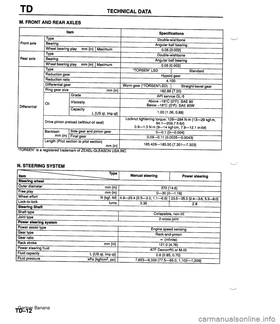
TECHNICAL DATA --- M. FRONT AND REAR AXLES Specifications TY pe Bearing Angular ball bearing 0.05 10.002) Front axle Rear axle - Wheel bearing play mm {in) I Maximum Bearina Anaular ball bearina . .. Wheel bearina plav mm {in) I Maximum " " 0.05 {0.002) 'TORSEN" LSD I Standard TY pe Reduction aear Hvpoid sear Reduction ratio Differential aear 4.100 Worm near ("1ORSEN"LSD) I Straiaht-bevel gear - - Ring gear size mm {in) 1 Grade 182.88 17.201 API service GL-5 Oil 1 Viscosity Above -18°C {O°F): SAE 90 Below -18°C {O°F): SAE 80W Differential Capacity L {US at. Imp at) Locknut tightening torque: 128-284 N.m {I 3-29 kgf.m, 94.1-209.7 ft.lbf) Drive pinion preload (without oil seal) TORSEN" is a Backlash mm {in) . , egistered trademark of ZEXEL-GLEASON US, Side gear and pinion gear Final gear , INC Length (Pilot section to pilot section) mm (in N. STEERING SYSTEM Steering wheel Outer diameter mm {in} 1 370 11 4.6) Type item Free play mm {in) I 630 {O-1.18) Wheel effort N (kaf, Ibfl 14.9--29.4{0.5--3.0, 1.1-4.6) 123.545.3 12.A4.6,5.3--8.0) turns I 3.36 1 2.8 I 1 Manual steering Steering Shaft Shaft type I Collapsible, non-tilt Power steering Joint type I 2-cross joint Power steering system Gear ratio 1 m (infinite) Rack stroke rnm {in) I 121 .O 14.76) Power assist type Engine speed sensing Power steering fluid Fluid capacity L {US qt, Imp qt} Fluid pressure kPa {kgf/cm2, psi) Gear type - - ATF DexrongII oi M-111 0.8 {0.85,0.70) 7,603--8,339 (77.5850, 1 ,I 02-1,209) Rack-and-pinion Gartner Banana
Page 1122 of 1708

TECHNICAL DATA R. SUSPENSION Front sus~ension I i/ Differential - . - ~- Coil springs MT I AT Shock absorbers "TORSEN" LSD TY ~a Cylindrical double-acting, low-pressure gas charged Standard Stabilizer Double-wishbone Torsion bar Wire diameter mm {in) Coil inner diameter mm {in} Rear suspension Tv~e I Double-wishbone TY pe Diameter mm {in) 20.0 (0.79) I Identification color 11 .O {0.43} 83.0 f3.27) . . Free length mm {in) Coil number 19.0 {0.75} . . 292.5 (1 1.52) 1 302.0 {I 1.89) 6.32 I - . I1 . ,I . , I Shock absorbers Cylindrical double-acting, low-pressure gas charged White I I Identification color I Yellow I Green I Blue Torsion bar 12.0 (0.471 1 11 .O 10.43) .a Stabilizer TYPe Diameter mm {in) Coil springs Wheel alignment I Front wheel alignment (Unladen'') I I - Caster angle*3 King pin angle I tun'aoen 'I 1 Camber angle'2 -0°43' 2 30' I I - Wire diameter mm {in) Coil inner diameter mm {in) Free length mm {in} Coil number Maximum steering angle 4O26' -c 45' 11 "20' Rear wheel alignment ,, l-l_A_-*i, *1 Fuel tank full; radiator coolant and engine oil at specified level, and spare tire, jack, and tools in designated position. *2 Difference between left and right must not exceed lo. *3 Difference between left and right must not exceed 1'30'. 10.1 (0.40) Inner Outer 10.2 I0.40) mm (in) Camber ana~e*~ J 3 + 3 10.12 r 0.12) 0°18' 2 18' -. - 3 r 3 {0.12 2 0.12) 0'24' 2 45' 37O23' 2 2" 32O32' 2 2" Total toe-in 83.0 i3.27) U' mm {in} degree 348.5 113.72) Total toe-in 356.5 {I 4.04) dearee 7.68 0'18' & 18' 7.96 Gartner Banana
Page 1124 of 1708

SPECIAL TOOLS .................... GENERAL INFORMATION ST- 2 ..................................... ENGINE ST- 3 CLUTCH AND MANUAL TRANSMISSION ...... ST- 4 ................. AUTOMATIC TRANSMISSION ST- 5 .............................. DIFFERENTIAL ST- 6 ................... FRONT AND REAR AXLES ST- 7 ......................... STEERING SYSTEM ST- 7 .......................... BRAKING SYSTEM ST- 9 ........... FRONT AND REAR SUSPENSIONS ST-1 0 CHECKERS AND OTHER EQUIPMENT ........ ST-10 4SUOTX-001 Gartner Banana
Page 1129 of 1708

ST SPECIAL TOOLS DIFFERENTIAL rooL NUMBER a DESCRIPTION PRIORITY TOOL NUMBER~ DESCRIPTION PRIORITY ILLUSTRATION 49 F027 005 Attachment @62 Hanger, differential carrier Collar Adjustment wrench, side bearing 49 8531 565 Pinion model 49 GO30 338 Attachment E 49 F027 004 Attachment @80 Gauge body, pinion height 49 BOO1 795 Installer, oil seal 49 0305 555 Sauge block 49 U027 003 Installer, oil seal nstaller, rubber wshing Holder, coupling ilange Gartner Banana