air condition MAZDA MX-5 1994 Repair Manual
[x] Cancel search | Manufacturer: MAZDA, Model Year: 1994, Model line: MX-5, Model: MAZDA MX-5 1994Pages: 1708, PDF Size: 82.34 MB
Page 245 of 1708

F ON-BOARD DIAGNOSIS SYSTEM Procedure - Set conditions to deactivate each switch a All accessories OFF a Transmission in neutral a All pedals released Verify that monitor lamp does not illuminate Neutral and Clutch switches (MT) Parklneutral switch (AT) Depress clutch pedal Verify that monitor lamp does not illuminate Return transmission to neutral NO PC: a Neutral or clutch switch malfunction (Refer to F-146) a Open circuit in related wire harness a Powertrain control module (engine) terminal 1V malfunction (Refer to page F-146) - Shift transmission into gear Verify that monitor lamp illuminates with clutch pedal is re- leased PC: a Clutch switch malfunction (Refer to page F-157) 35UOFX-046 I ParWneutral switch OK Shift into P or N range Check each switch and related wire harness a Clutch and Neutral switch :Refer to page F-I57 a Idle switch (in throttle position sensor) :Refer to page F-154 a Stoplight switch :Refer to Section T Headlight switch :Refer to Section T 1 Check each switch as described I I NO - ldle switch (in throttle position sensor) a Blower switch :Refer to Section T a Air conditioning sensor :Refer to Section U a Rear window defroster switch :Refer to Section T a ParWneutral switch :Refer to Section K YES PC: a ParWneutral switch malfunction (Refer to Section K) a Open or short circuit in related wire harness a PCME terminal 1 V voltage incorrect (Refer to page F-I 46) PCME malfunction - Shift transmission into L, S, D, or P range Check that monitor lamp illuminates 35UOFX-06 NO + YES I 1 I ldle switch OK I L I PC: Throttle position sensor malfunction (Refer to page F-144) a Short circuit in wire harness from throttle position sensor to PCME a PCME terminal 1 N voltage incorrect (Refer to page F-145) a PCME malfunction - Depress accelerator pedal and check that monitor lamp illu- minates f NO --c YES PC: a Throttle position sensor malfunction (Refer to page F-144) Open circuit in wire harness from throttle position sensor to PCME PCME terminal 2M voltage incorrect (Refer to page F-146) Release acceleration pedal and check that monitor lamp does not illuminate 2 YES I I Gartner Banana
Page 246 of 1708

ON-BOARD DIAGNOSIS SYSTEM Stoplight switch OK Release brake pedal Stoplight switch (MT) Headlight switch PC: Stoplight switch malfunction (Refer to Section T) 0 Open circuit in wire harness from stoplight switch to powertrain control module (engine) Powertrain control module (engine) terminal 10 malfunction (Refer to page F-145) Headlight switch OK Turn OFF headlight switch I I NO ---c L, Blower switch YES Depress brake pedal and verify that monitor lamp illuminates PC: Headlight switch malfunction (Refer to section T) Open circuit in wire harness from headlight switch to powertrain control module (engine) Powertrain control module (engine) terminal 1 U malfunction (Refer to page F-146) Turn ON headlight switch Verify that monitor lamp illuminates Verify that monitor lamp illuminates NO - I YES YES Blower switch OK Turn OFF blower switch Air conditioning sensor PC: Blower switch malfunction (Refer to section T) 0 Open circuit in wire harness from blower switch to powertrain control module (engine) 0 Powertrain control module (engine) terminal IS malfunction (Refer to page F-146) 1 I YES I ' Set fan speed control to low position Turn air conditioning sensor ON, and verify that monitor lamp illuminates PC: Air conditioning sensor malfunction (Refer to Section U) Blower switch malfunction Open circuit in wire harness from air conditioning sensor to blower switch Powertrain control module (engine) terminal 1Q malfunction (Refer to page F-146) NO' 4 Air conditioning sensor OK Turn air conditioning sensor and blower switch OFF Rear window defroster switch Turn rear window defroster switch ON Is monitor lamp illuminated? NO PC: Rear window defroster switch malfunction (Refer to Section T) Open circuit in wire harness (Rear window defroster switch - PCME) PCME terminal 2L voltage incorrect (Refer to page F-146) PCME malfunction YES Turn rear window defroster switch OFF u Rear window defroster switch OK Gartner Banana
Page 271 of 1708

PRESSURE REGULATOR CONTROL SYSTEM PRESSURE REGULATOR CONTROL SYSTEM DATA LINK CONNECTOR - CLUTCH SWITCH (MT) (TEN TERMINAL) PARKINEUTRAL SWITCH (PCMT) (AT) THROTTLE POSITION SENSOR L 1 ,,,, INTAKE AIR TEMPERATURE 1 SENSOR (IN MASS AIRFLOW SENSOR) -;- ENGINE COOLANT TEMPERATURE SENSOR PRC SOLENOID VALVE CRANKSHAFT POSITION SENSOR PRESSURE REGULATOR PCME I Above 90°C {194OF} ( Above 70°C {158'F} I Throttle valve closed throttle position or no load condition I Approx. 150 1 I Operating condition Coolant temperature I Intake air temperature I Engine condition I I To prevent percolation of the fuel during hot restart idle, vacuum to the pressure regulator is momentarily cut, and the fuel injection pressure is increased to slightly more than 284 kPa (2.9 kgf/cm2, 41.2 psi}. Operating time (sec) Gartner Banana
Page 274 of 1708

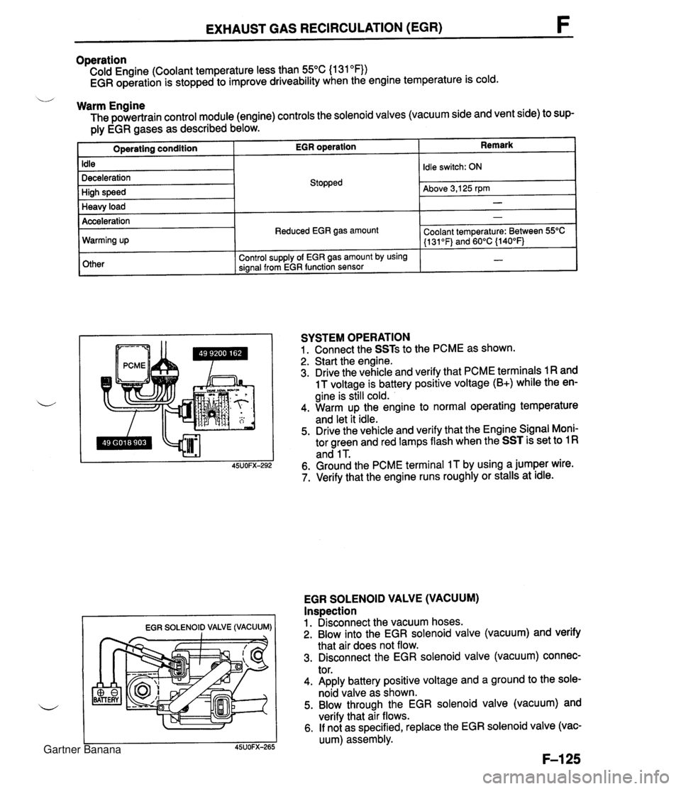
EXHAUST GAS RECIRCULATION (EGR) Operation Cold Engine (Coolant temperature less than 55°C (1 31 OF)) EGR operation is stopped to improve driveability when the engine temperature is cold. u Warm Engine The powertrain control module (engine) controls the solenoid valves (vacuum side and vent side) to sup- ply EGR gases as described below. Remark Operating condition Idle Deceleration High speed Heavy load EGR SOLENOID VALVE (VACUUM) I I EGR operation Acceleration Warming up Other SYSTEM OPERATION 1. Connect the SSTs to the PCME as shown. 2. Start the engine. 3. Drive the vehicle and verify that PCME terminals 1 R and 1 T voltage is battery positive voltage (B+) while the en- gine is still cold. 4. Warm up the engine to normal operating temperature and let it idle. 5. Drive the vehicle and verify that the Engine Signal Moni- tor green and red lamps flash when the SST is set to 1 R and 1 T. 6. Ground the PCME terminal IT by using a jumper wire. 7. Verify that the engine runs roughly or stalls at idle. Stopped EGR SOLENOID VALVE (VACUUM) Inspection 1. Disconnect the vacuum hoses. 2. Blow into the EGR solenoid valve (vacuum) and verify that air does not flow. 3. Disconnect the EGR solenoid valve (vacuum) connec- tor. 4. Apply battery positive voltage and a ground to the sole- noid valve as shown. 5. Blow through the EGR solenoid valve (vacuum) and verify that air flows. 6. If not as specified, replace the EGR solenoid valve (vac- uum) assembly. Idle switch: ON Above 3,125 rpm - Reduced EGR gas amount Control supply of EGR gas amount by using signal from EGR function sensor - Coolant temperature: Between 55OC (1 31 OF) and 60°C {140°F) - Gartner Banana
Page 280 of 1708

FUEL EVAPORATIVE SYSTEM FUEL EVAPORATIVE SYSTEM DESCRIPTION The fuel evaporative system consists of the fuel vapor valve, the two-way check valve, the charcoal can- ister, the purge solenoid valve, the powertrain control module (engine), and the input devices. The amount of evaporative fumes introduced into the engine and burned is controlled by the solenoid valve in relation to the engine's operating conditions. To maintain the best engine performance, the solenoid valve is controlled by the powertrab control module (engine). THROTTLE 1-1 POSITION SENSOR I1 I I (IDLE SWITCH) 7 BAROMETIC ABSOLUTE PRESSURE SENSOR PARWNEUTRAL SWITCH (AT) MASS AIRFLOW SENSOR CRANKSHAFT POSITION SENSOR (SGT-SIGNAL) n - DUTY - LOW HIGH (ENGINE) CHARCOAL PURGE SOLENOID VALVE CANISTER HEATED OXYGEN SENSOR ENGINE COOLANT POWERTRAIN TEMPERATURE SENSOR CONTROL MODULE CHECK VALVE # 11 FUEL VAPOR VALVE Operation The purge solenoid valve is controlled by duty signals from the powertrain control module (engine) to per- form purging of the charcoal canister. Purging is done when these conditions are met: i/ 1. After warm-up. 2. Driving in gear. 3. Accelerator pedal depressed (idle switch OFF). 4. Heated oxygen sensor functioning normally. Gartner Banana
Page 285 of 1708

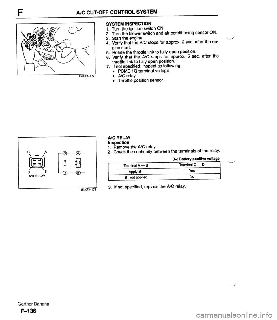
F A/C CUT-OFF CONTROL SYSTEM D B AIC RE LAY SYSTEM INSPECTION 1. Turn the ignition switch ON. 2. Turn the blower switch and air conditioning sensor ON. 3. Start the engine. d 4. Verify that the A/C stops for approx. 2 sec. after the en- gine start. 5. Rotate the throttle link to fully open position. 6. Verify that the A/C stops for approx. 5 sec. after the throttle link to fully open position. 7. If not specified, inspect as following. PCME 1Q terminal voltage A/C relay Throttle position sensor AIC RELAY Inspection 1. Remove the A/C relay. 2. Check the continuity between the terminals of the relay. 3. If not specified, replace the A/C relay. B+: Battery positive voltage Terminal A - B Apply B+ B+ not applied Terminal C - D Yes No Gartner Banana
Page 288 of 1708

COOLANT FAN CONTROL F COOLANT FAN The coolant fan rotates at a constant velocity. 'L / Operation Condition TEN TERMINAL (DATA LINK CONNECTOR) IDLE SWITCH -----' OFF EXCEPT AT STARTING 'I ENGINE COOLANT TEMPERATURE ABOVE 97C0 (206.6F0) 1 COOLANT FAN - - ENGINE COOLANT TEMPERATURE SENSOR FAILED I A/C OPERATING CONDENSER FAN The condenser fan is operated by PCME. r The condenser fan rotates at a constant velocity. Operation Condition Except during acceralation Except at starting Other than wide open throttle Air conditioner is operating The condenser fan operates when above-mentioned conditions are satisfied. Engine coolant temperature is above 108°C (226.4OFj. TEN terminal grounded and idle switch off. Gartner Banana
Page 294 of 1708

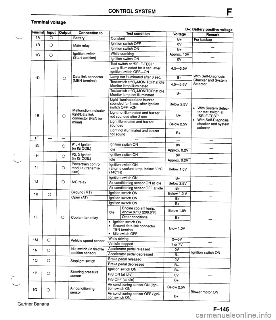
CONTROL SYSTEM F Terminal voltage B+: Battery positive voltage Test condition I Voltage I Remark - - - - - - - - - - - - - - - - - - Connection to Battery Constant Ignition switch OFF Main relay - B+ OV lgnition switch (Start position) For backup - Ignition switch ON While cranking Lamp illuminated for 3 sec. after 1 4.5-5.5V ianition switch OFF+ON 1 B+ Approx. 1 OV Ignition switch ON - - OV Data link connector (MEN terminal) Test switch at "SELF-TEST" .. Lamp not illuminated after 3 sec. Test switch at "02 MONITOR" at idle Monitor lam illuminated & 4.5-5.5v . . I Malfunction indicator IighVData link connector (FEN ter- minal) With Self-Diagnosis Checker and System Selector Test switch at "02 MONITOR" at idle Monitor lamp not illuminated Light illuminated and buzzer sounded for 3 sec. after ignition switch OFF-ON B+ tor tesiswitch at "SELF-TEST" With Self-Diagnosis checker and system selector Below 2.5V 1 Light illuminated and buzzer sounded 1 Below 2.5V I With System Selec- Light not illuminated and buzzer not sounded after 3 sec. I Light not illuminated and buzzer 1 n. 1 B+ not sound I D+ 1 - #I, 4 lgniter (in IG COIL) #2,3 Igniter (in IG COIL) Powertrain control module (transmis- sion) - Ignition switch ON Idle Ignition switch ON Idle lgnition switch ON (Engine coolant temp, below 60°C {I 40°F)) Ignition switch ON AtC relay Air conditioning sensor ON at idle Air conditioning sensor OFF at idle Ground (MT) - OV Approx. 0.2V OV Approx. 0.2V Below 1 .OV B+ Below 2.5V B+ - - - - , * Open (AT) - Ignition switch ON ( Below 1 .O V I Engine coolant temp. I Below .OV I ldle Above 97°C (206.6OF1 Ignition switch ON I I B+ Ignition switch ON Coolant fan relay B+ . - Other conditions lgnition switch On dround data link connector TEN terminal I Blow 1.0" I B+ Vehicle speed sensor ldle switch OFF While driving Vehicle sto~wed ldle switch (in throttle position sensor) 2-5V 1 or 7V . , Accelerator pedal released Accelerator ~edal de~ressed - Stoplight switch OV B+ Brake pedal released Brake ~edal deoressed lgnition switch ON Steering pressure sensor OV B+ I I - Ignition switch ON B+ - PIS ON (at idle) PIS OFF (at idle) Air conditioning sensor Air conditioning sensor ON (Igni- tion switch ON) Air conditioning sensor OFF (Igni- tion switch ON) OV B+ - Below 2.5V B+ Blower motor ON Gartner Banana
Page 295 of 1708

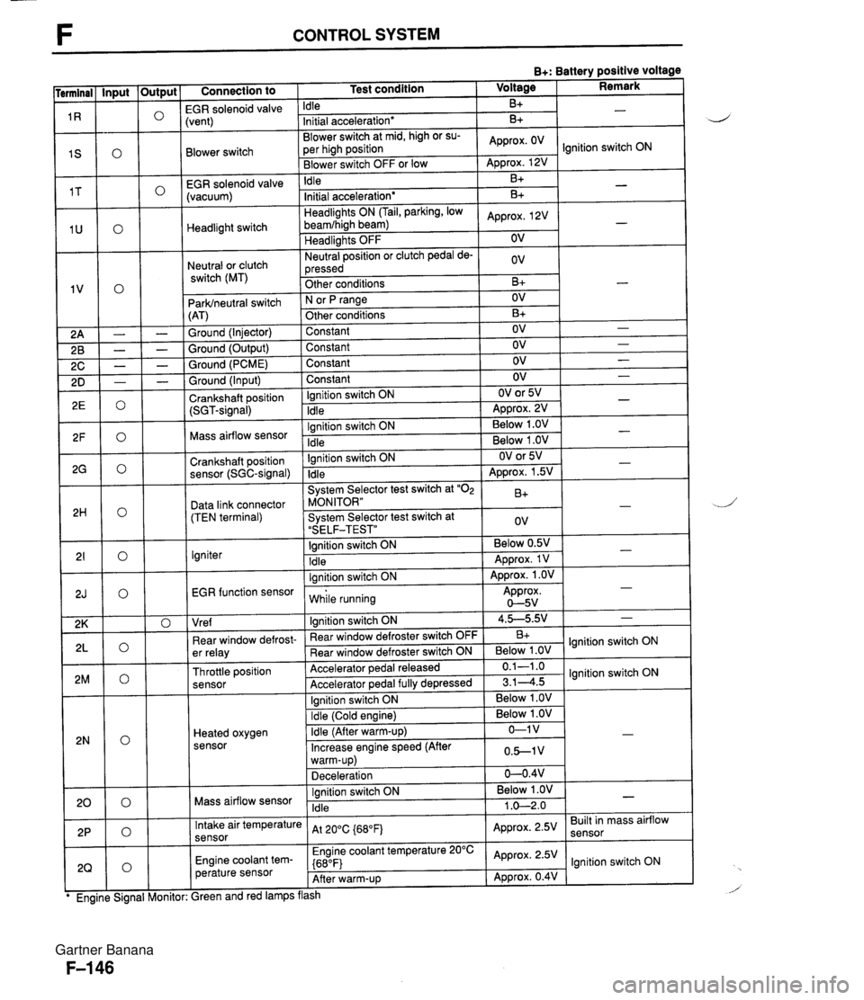
F CONTROL SYSTEM B+: Battery positive voltage Connection to 1 Test condition 1 Voltage I Remark I -- EGR solenoid valvi Idle B+ Blower switch -- EGR solenoid valve (vacuum) :vent) Initial acceleration* Blower switch at mid, high or su- per high position Blower switch OFF or low Headlight switch Neutral or clutch switch (MT) B+ Idle ParWneutral switch (AT) Ground (Injector) Ground (Output) Ground (PCME) Approx. OV - Approx. 12V B+ Headlights ON (Tail, parking, low beamfhigh beam) Headlights OFF Neutral position or clutch pedal de- pressed Other conditions Ground (Input) Crankshaft position (SGT-signal) Ignition switch ON N or fJ range Other conditions Constant Constant Constant -. Mass airflow sensor .. . . EGR function sensor I while running Approx. 0-5v Initial acceleration* Approx, 2V OV ov B+ Constant Ignition switch ON Idle Crankshaft position sensor (SGC-signal) Data link connector (TEN terminal) Igniter I I I Vre f I lanition switch ON 1 4.5-5.9.' 1 - B+ - OV B+ OV OV OV Ignition switch ON Idle - - - OV OV or 5V ADD~OX. 2V - - Ignition switch ON Idle System Selector test switch at "02 MONITOR" System Selector test switch at "SELF-TEST" Ignition switch ON Idle lanition switch ON I . . I I 1 Ignition switch ON I Below 1 .OV I I - - . . Below 1 .OV Below 1 .OV ear window defrost- er relay Throttle position sensor Heated oxygen sensor - OV or 5V Approx. 1.5V B+ ov Below 0.5V Approx. 1 V Approx. 1 .OV - - - " Rear window defroster switch OFF Rear window defroster switch ON Accelerator pedal released Accelerator ~edal fullv de~ressed Mass airflow sensor B+ Below 1 .OV 0.1-1 .o 3.14.5 Intake air temperature sensor Engine coolant tem- perature sensor lgnition switch ON lgnition switch ON Ignition switch ON Idle ireen and red lamps flash At 200C {680Fj Engine coolant temperature 20°C {680F) After warm-up Below 1 .OV 1 .O-2.0 - Approx. 2.5V Approx. 2.5V Approx. 0.4V Built in mass airflow lgnition switch ON Gartner Banana
Page 296 of 1708

CONTROL SYSTEM F Connection to I Test condition I Hot condition: Enaine coolant Input - temp. above 70°C (1 58"~) and in- PRC solenoid valve take air temp. above 50°C (122°F) for 150 sec. after enaine startina Output 0 0 0 0 0 0 0 0 0 " " Other conditions lanition switch On - Condenser fan relay Engine coolant temp. Idle above 108°C 1226°F) I I Other conditions ' I lgnition switch ON Fuel pump relay ldle I I lanition switch ON Fuel injector No.1 1,900 rpm (After warm-UD) I lgnition switch ON Fuel injector No.2 ldle Deceleration from 3,000 rprn to 1,900 rpm (After warm-up) lgnition switch ON IAC valve ldle lgnition switch ON Purge solenoid valve ldle Fuel injector No.3 lgnition switch ON ldle Deceleration from 3,000 rpm to 1,900 rpm (After warm-up) lanition switch ON Fuel injector No.4 Idle Deceleration from 3,000 rpm to 1,900 rpm (After warm-up) Below 1 .OV -1 Below 1 .OV B+ - Approx. OV Engine Signal Moni- * Engine Signal Moni- tor: Green and red Approx. 12V I lamps flash B+: Battery positive voltage Voltage I Remark * Engine Signal Moni- tor: Green and red Engine Signal Moni- Gartner Banana