engine oil MAZDA MX-5 1994 Manual PDF
[x] Cancel search | Manufacturer: MAZDA, Model Year: 1994, Model line: MX-5, Model: MAZDA MX-5 1994Pages: 1708, PDF Size: 82.34 MB
Page 410 of 1708

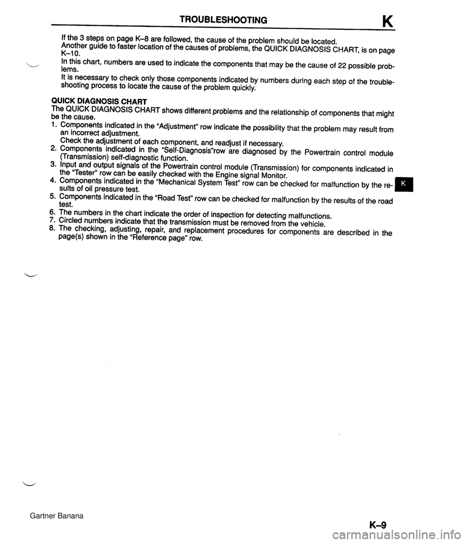
TROUBLESHOOTING If the 3 steps on page K-8 are followed, the cause of the problem should be located. Another guide to faster location of the causes of problems, the QUICK DIAGNOSIS CHART, is on page K-1 0. b In this chart, numbers are used to indicate the components that may be the cause of 22 possible prob- lems. It is necessary to check only those components indicated by numbers during each step of the trouble- shooting process to locate the cause of the problem quickly. QUICK DIAGNOSIS CHART The QUICK DIAGNOSIS CHART shows different .problems and the relationship of components that might be the cause. 1. Components indicated in the "Adjustment" row indicate the possibility that the problem may result from an incorrect adjustment. Check the adjustment of each component, and readjust if necessary. 2. Components indicated in the "Self-DiagnosisWrow are diagnosed by the Powertrain control module (Transmission) self-diagnostic function. 3. Input and output signals of the Powertrain control module (Transmission) for components indicated in the "Tester" row can be easily checked with the Engine signal Monitor. 4. Components indicated in the "Mechanical System Test" row can be checked for malfunction by the re- sults of oil pressure test. 5. Components indicated in the "Road Test" row can be checked for malfunction by the results of the road test. 6. The numbers in the chart indicate the order of inspection for detecting malfunctions. 7. Circled numbers indicate that the transmission must be removed from the vehicle. 8. The checking, adjusting, repair, and replacement procedures for components are described in the page(s) shown in the "Reference page" row. Gartner Banana
Page 423 of 1708

K MECHANICAL SYSTEM TEST MECHANICAL SYSTEM TEST PREPARATION SST STALL TEST 49 0378 400A Gauge set, oil pressure 49 801 9 901 Gauge, oil pressure For oil pressure test For oil pressure test This test is performed to determine if there is slippage of the friction elements or malfunction of the hy- draulic components. Preparation 1. Check the engine coolant, engine oil, and ATF levels before testing. 2. Warm the engine thoroughly to raise the ATF temperature to operating level (50--80°C, 122-176°F). 3. Engage the parking brake and use wheel chocks at the front and rear of the wheels. ENGAGE PARKING BRAKE WARM UP ENGINE COOLANT LEVEL ENGINE OIL LEVEL TEMPERATURE 60-70°C (1 40-1 58°F) ATF LEVEL Gartner Banana
Page 425 of 1708

K MECHANICAL SYSTEM TEST Evaluation of Stall Test 4bove specification Nithin specification In all ranges In D (Normal), and L ranges In D (Normal) range only In R range only 3elow specification Possible cause I Worn oil Dumo Oil leakage from oil pump, control Insufficient line pressure Direct clutch and overdrive one-way clutch sli~~ina Rear clutch slipping One-way clutch slipping Low and reverse brake slipping Front clutch slipping Perform road test to determine if this is caused by low and reverse brake or front clutch as follows: a) Effective engine braking in L range . . . . . . . . . . Front clutch b) No enaine brakina in L range . . . . . Low and reverse brake All ~hiftcont~elements within transmission are functioning normally Engine out of tune One-wav clutch sli~~ina within toraue converter Gartner Banana
Page 427 of 1708

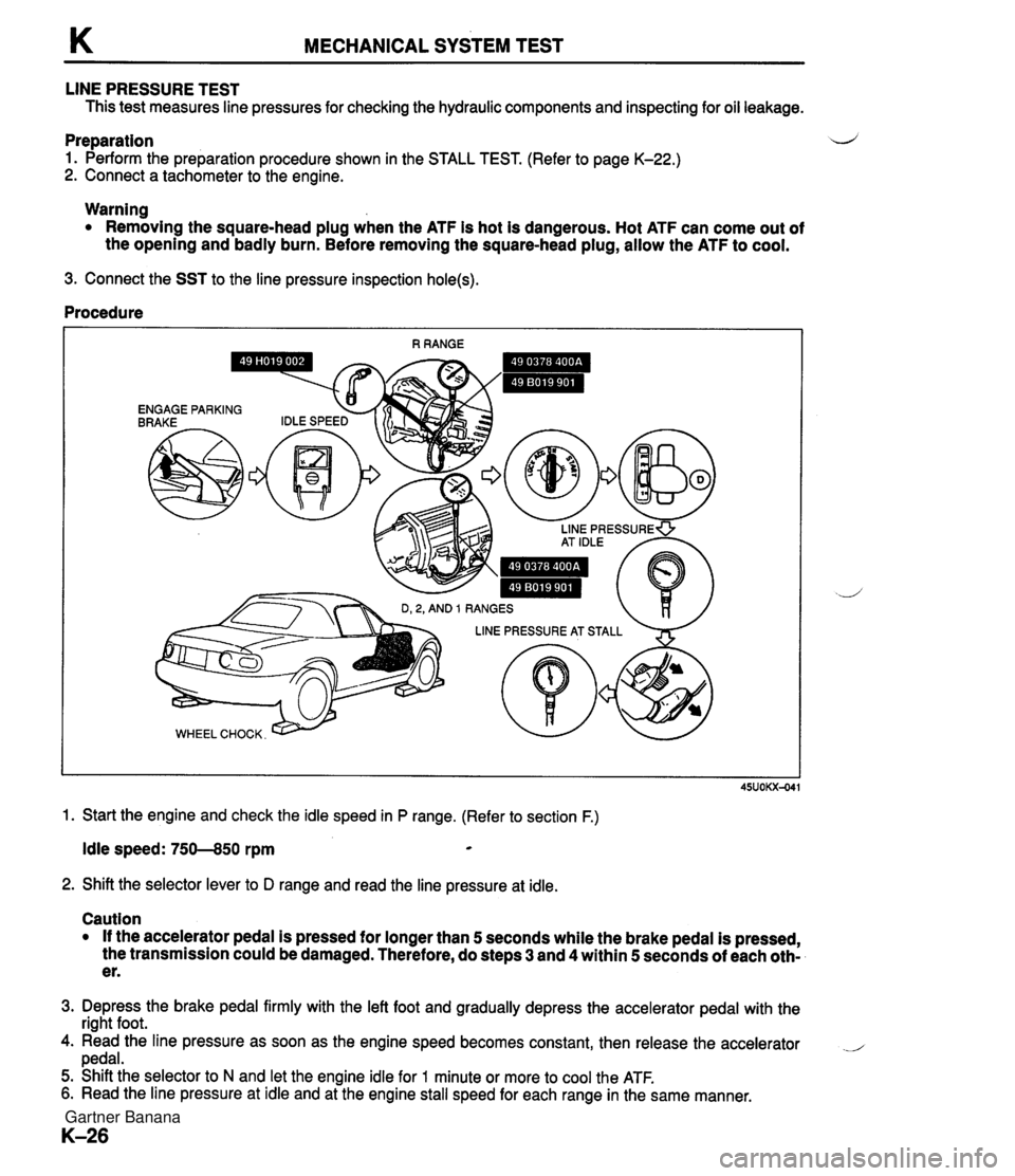
K MECHANICAL SYSTEM TEST LINE PRESSURE TEST This test measures line pressures for checking the hydraulic components and inspecting for oil leakage. Preparation d 1. Perform the preparation procedure shown in the STALL TEST. (Refer to page K-22.) 2. Connect a tachometer to the engine. Warning Removing the square-head plug when the ATF is hot is dangerous. Hot ATF can come out of the opening and badly burn. Before removing the square-head plug, allow the ATF to cool. 3. Connect the SST to the line pressure inspection hole(s). Procedure 1. Start the engine and check the idle speed in P range. (Refer to section F.) Idle speed: 750--850 rpm * 2. Shift the selector lever to D range and read the line pressure at idle. Caution If the accelerator pedal is pressed for longer than 5 seconds while the brake pedal is pressed, the transmission could be damaged. Therefore, do steps 3 and 4 within 5 seconds of each oth- er. 3. Depress the brake pedal firmly with the left foot and gradually depress the accelerator pedal with the right foot. 4. Read the line pressure as soon as the engine speed becomes constant, then release the accelerator .- pedal. 5. Shift the selector to N and let the engine idle for 1 minute or more to cool the ATF. 6. Read the line pressure at idle and at the engine stall speed for each range in the same manner. Gartner Banana
Page 430 of 1708

ROAD TEST K ROAD TEST A road test is necessary to inspect for problems in the different gear ranges. If a range or function tar- b geted by the road test is found to have any problem, refer to the ELECTRONIC SYSTEM COMPONENT segment or the TRANSMISSION, OIL COOLER, DRIVE PLATE, and SHIFT MECHANISM segments of this section. Do the road test only when the ATF is 50-80°C (1 22-1 76°F). D-RANGE TEST Shift Point, Shift Pattern, and Shift Shock 1. Shift the selector lever to D range and select the Normal mode. 2. Accelerate the vehicle with half-and wide open throttle opening. 3. Verify that 1-2, 2-3, and 3-4 upshifts, downshifts, and lockup are obtained. The shift points must be as shown in the D range (Normal) shift diagram. Note There is fourth gear is any of the following conditions. A The cruise control is operating, and there is an 8kmIh (5 mph} difference between the preset cruise speed and the vehicle speed. B The SET or RESUME switch is ON. There is no lockup when water temperature is below 50°C (1 22°F) or in the throttle valve closed posi- tion. 4. Check the upshifts for shift shock or slippage in the same manner. 5. While driving in overdrive, shift the selector lever to S range and verify that 4-3 downshift immediately occurs, then decelerate and verify that engine braking effect is felt in only third gear and 2nd gears. D-range (Normal) shift diagram p'yJ ..,,*sw.. LOCKUP AVAILABLE WHEN ACCELERATING AND CRUSING LOCKUP AVAILABLE WHEN COASTING 0 20 (1 2) 40 (25) 60 (37) 80 {50) 100 (63) 1 20 (75) 140 (87) 1 60 (99) VEHICLE SPEED kmlh {mph) Gartner Banana
Page 548 of 1708

TRANSMISSION K TRANSMISSION UNIT (INSTALLATION) Preparation SST Wrench d b For installation of torque converter bolts 1. On level ground, raise the vehicle and support it evenly on safety stands. 2. Install in the order shown in figure, referring to Installation Note. 3. Fill the transmission with the specified amount and type of the ATF after installation. 4. Warm up the engine, inspect for oil leakage, and verify correct transmission operation. 49 0259 440 Holder, rnainshaft For prevention of oil leakage Gartner Banana
Page 583 of 1708

L OUTLINE, TROUBLESHOOTING GUIDE, PROPELLER SHAFT OUTLINE SPECIFICATIONS TROUBLESHOOTING GUIDE Enginefrransmission Problem I Possible Cause BP DOHC Vibration Worn universal joint Bent propeller shaft Worn slip yoke splines Runout of propeller shaft Unbalanced propeller shaft Item MI 5M-D Abnormal noise NC4A-EL Worn or damaged universal joint Worn slip yoke splines PROPELLER SHAFT PREPARATION SST 1,001 (39.41) 816 (32.1) 60.5 ( 2.38) Length mm {in) Outer diameter mm{in) Holder, main shaft Ll L2 D For prevention of oil leakage Action 1 Page Replace Replace Replace Replace Replace Replace Replace Gartner Banana
Page 608 of 1708

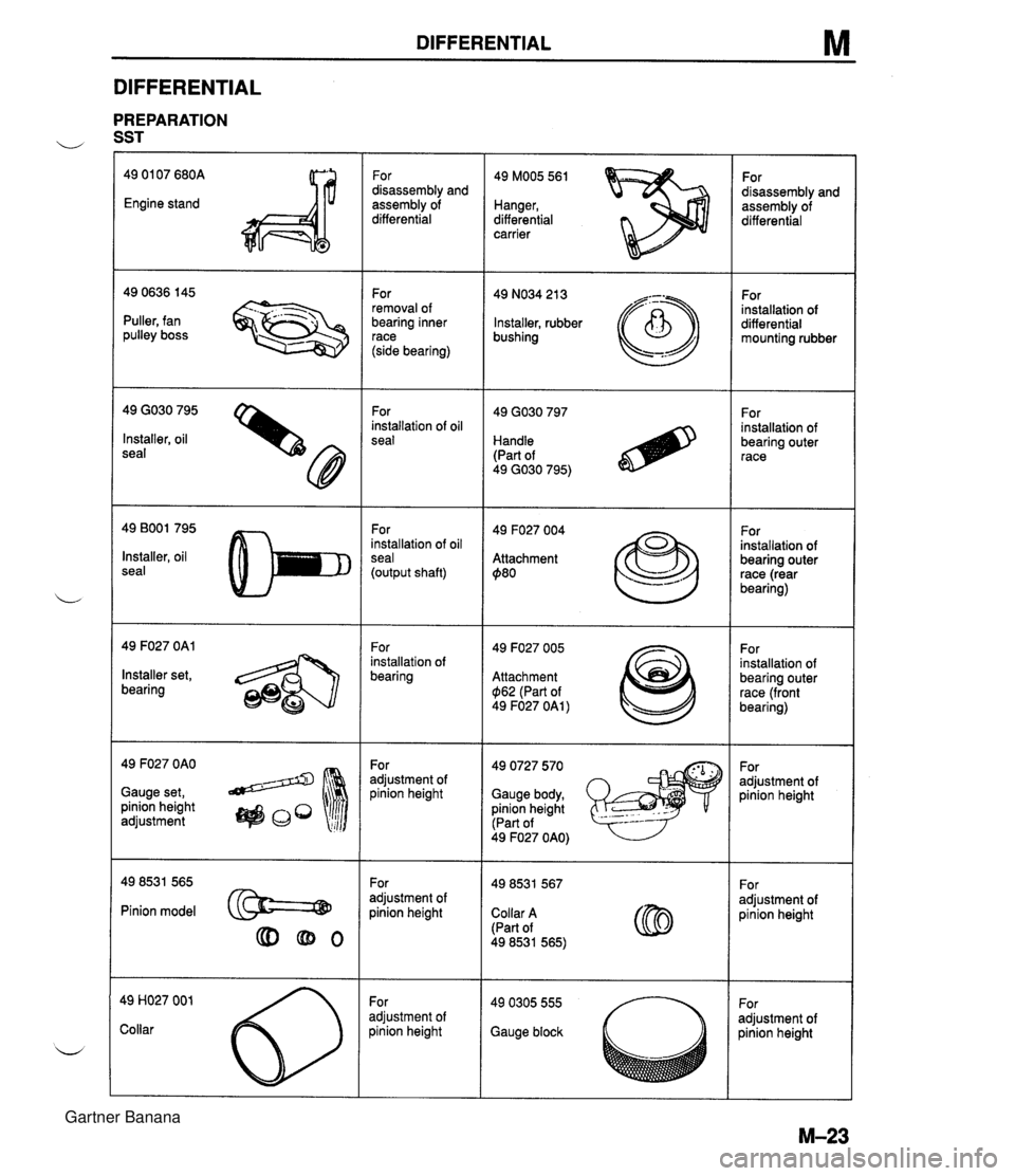
DIFFERENTIAL M DIFFERENTIAL PREPARATION u SST 49 01 07 680A Engine stand For disassembly and assembly of differential 49 MOO5 561 Hanger, differential carrier For disassembly and assembly of differential For removal of bearing inner race (side bearing) 49 NO34 21 3 Installer, rubber bushing For installation of differential mounting rubber - --.. - Puller, fan pulley boss 49 GO30 795 Installer, oil seal For installation of oil seal For installation of bearing outer race Handle (Part of 49 GO30 795) 49 BOO1 795 Installer, oil seal For installation of oil seal (output shaft) 49 F027 004 Attachment $80 For installation of bearing outer race (rear bearing) 49 F027 OAl For installation of bearing 49 F027 005 Attachment $I62 (Part of 49 F027 OAl ) For installation of bearing outer race (front bearing) Installer set, bearing 49 F027 OAO Gauge set, pinion height adjustment 49 0727 570 Gauge body, pinion height (Part of For adjustment of pinion height For adjustment of pinion height 49 F027 OAO) For adjustment of pinion height For adjustment of oinion height Pinion model @==@ Collar A (Part of 49 8531 565) For adjustment of oinion height adjustment of )inion height Gauge block Gartner Banana
Page 628 of 1708

Before beginning any service procedure. refer to section T of this manual for I air bag system service warnings and audio antitheft system alarm conditions . STEERING SYSTEM INDEX ....................................... N- 2 OUTLINE ..................................... N- 4 SPECIFICATIONS ........................... N- 4 MANUAL STEERING .......................... N- 4 PREPARATION ............................. N- 4 ................ TROUBLESHOOTING GUIDE N- 5 BOOT ...................................... N- 6 STEERING WHEEL AND COLUMN ........... N- 8 ............. STEERING GEAR AND LINKAGE N-12 ENGINE SPEED SENSING POWER STEERING .......................... N-18 PREPARATION ............................. N-18 TROUBLESHOOTING GUIDE ................ N-20 AIR BLEEDING ............................. N-21 POWER STEERING FLUID ................... N-22 STEERING WHEEL AND COLUMN ........... N-24 STEERING GEAR AND LINKAGE ............. N-25 POWER STEERING OIL PUMP ............... N-33 DRIVE BELT ................................ N-37 25UONX-001 Gartner Banana
Page 631 of 1708

N OUTLINEIMANUAL STEERING OUTLINE SPECIFICATIONS Steering wheel Steering shaft and joint d Type Steering gear Outer diameter mm {in) I 370 {I 4.6) I Manual steering Power steering Lock-to-lock turns Shaft ~oinr Power assist 3.36 2-cross joint - I Engine speed sensing Gear Gear ratio 2.8 Rack-and-pinion m (infinite) Rack stroke mm {in} Power steering fluid MANUAL STEERING Collapsible, non-tilt 121 .O i4.76) - I ATF DexronBII or M-111 ~luidca~acit~ L~S qt, Imp qt) I - PREPARATION SST 0.8 (0.85, 0.70) Preload attachment 25UONX-003 Hexagon wrench 49 GO30 797 Handle For removal of tie-rod end 49 1243 785 Installer, boot For measurement of pinion torque For installation of bushing 49 0208 701 A Boot air out tool - For removal and installation of adjusting cover For installation of tie-rod end boot 49 DO32 31 6 Protractor For removal of oil seal For tightening of adjusting cover Gartner Banana