engine oil MAZDA MX-5 1994 Owner's Guide
[x] Cancel search | Manufacturer: MAZDA, Model Year: 1994, Model line: MX-5, Model: MAZDA MX-5 1994Pages: 1708, PDF Size: 82.34 MB
Page 108 of 1708

ASSEMBLY Cylinder Head Gasket 1. Remove all foreign material from the top of the cylinder block. 2. Place the new cylinder head gasket in position. Cylinder Head 1. Install the cylinder head. 2. Apply clean engine oil to the bolt threads and seat faces. 3. Tighten the cylinder head bolts in two or three steps in the order shown. Tightening torque: 76-81 N-m (7.7--8.3 kgf.m, 56-60 ft4bf) Thermostat Housing 1. Remove all foreign material from the thermostat housing mounting surface. 2. Install a new O-ring and the thermostat housing. Tightening torque: 19-25 N.m (1.9-2.6 kgf.m, 14--18 ft-lbf) Seal Plate Install the seal plate on the cylinder head. Tightening torque: 7.9-10.7 N-m (80-110 kgfem, 70-95.4 in4bf) HLA 1. Apply clean engine oil to the friction surfaces. 2. If the HLA are being reused, install them in the position from which they were removed. 3. Verify that the HLA move smoothly in their bores. Gartner Banana
Page 109 of 1708

ASSEMBLY Camshaft Note The rear end of exhaust camshaft is grooved for the L/ crankshaft position sensor drive. 1. Apply clean engine oil to the camshaft journals and bear- ings. 2. Install the camshaft in position. CRANKSHAFT POSITION SENSOR DRIVE GROOVE 45UOBX-151 3. Apply silicone sealant to the shaded areas shown in the figure. Do not let any sealant get on the journal surfaces. 4. Install the camshaft caps according to the cap number and arrow mark. 5. Install the camshaft cap bolts, and tighten them in two or three steps in the order shown. Tightening torque: Il.3--14.2 N.m {ll5-l4S kgfem, 100-125 in4bf) ij 6. Apply a small amount of clean engine oil to the lip of a new camshaft oil seal. 7. Push the oil seal slightly in by hand. 8. Using a pipe and hammer, tap the oil seal in evenly until it is flush with the edge of the camshaft cap. Note Oil seal outer diameter: 48mm (1.89 in) Oil seal inner diameter: 34mm (1.34 in) Camshaft Pulley 1. Turn the camshafts until the camshaft dowel pins face straight up. 2. lnstall the camshaft pulleys with the I mark (intake side) or the E mark (exhaust side) straight up. Gartner Banana
Page 114 of 1708

ASSEMBLY B AUXILIARY PARTS Torque Specifications I FRONT OIL COOLER INSTALLATION REFER TO SECTION D Engine Hanger Install the front and rear engine hangers. Tightening torque: 38-51 N.m (3.8-5.3 kgf.m, 28-38 ft4bf) Gartner Banana
Page 115 of 1708

ASSEMBLY Dipstick, Dipstick Pipe 1. Apply a small amount of clean engine oil to the new 0- ring. 2. Push the dipstick pipe into the oil pan. u 3. Tighten the dipstick pipe bracket nut. Tightening torque: 7.9-10.7 N.m (80-1 10 kgfem, 70-95.4 in4bf) 4. lnstall the dipstick. Spark Plug lnstall the spark plugs. Tightening torque: 15-22 N.m (1 .%2.3 kgf-m, 11-1 6 ft4bf) Water Outlet Pipe 1. Remove all foreign material from the water outlet pipe mounting surface. 2. lnstall a new gasket and the water outlet pipe. Tightening torque: 19-25 N.m (1.9-2.6 kgf.m, 14--18 ft4bf) Oil Pressure Switch lnstall the oil pressure switch. Tightening torque: 12-17 N.m (1.2-1.8 kgf-m, 9-13 ft4bf) Gartner Banana
Page 116 of 1708

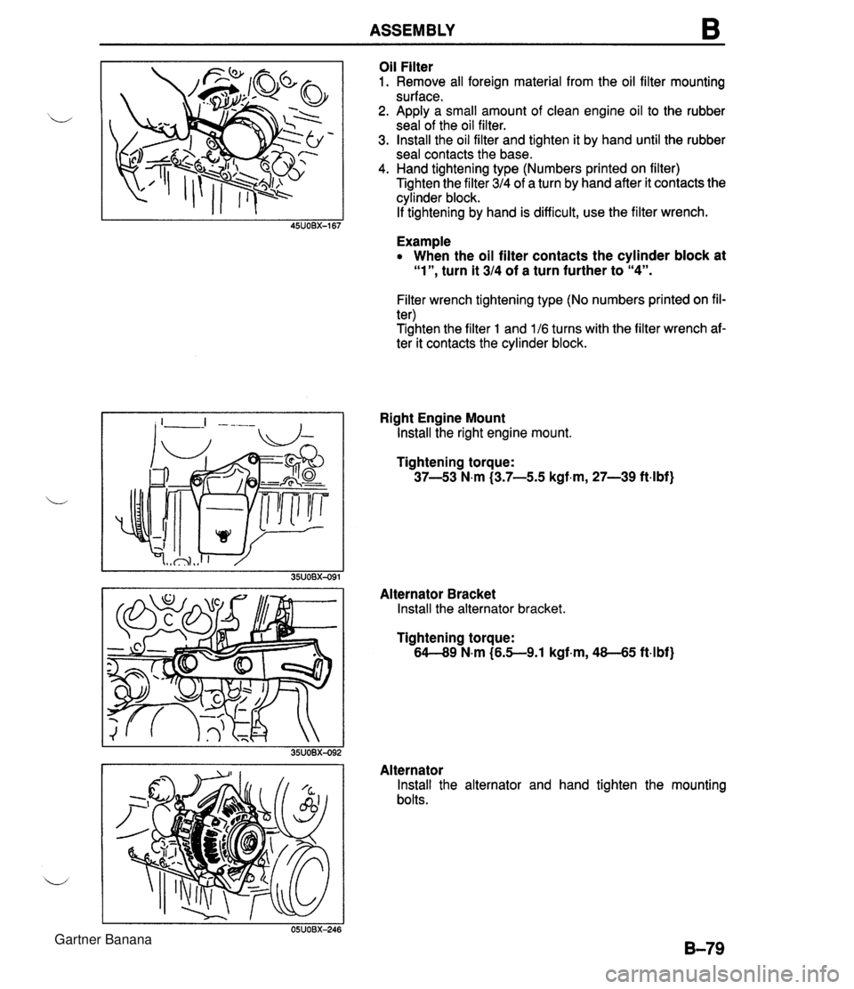
ASSEMBLY B Oil Filter 1. Remove all foreign material from the oil filter mounting surface. 2. Apply a small amount of clean engine oil to the rubber seal of the oil filter. 3. Install the oil filter and tighten it by hand until the rubber seal contacts the base. 4. Hand tightening type (Numbers printed on filter) Tighten the filter 314 of a turn by hand after it contacts the cylinder block. If tightening by hand is difficult, use the filter wrench. Example When the oil filter contacts the cylinder block at "l", turn it 314 of a turn further to "4". Filter wrench tightening type (No numbers printed on fil- ter) Tighten the filter 1 and 116 turns with the filter wrench af- ter it contacts the cylinder block. Right Engine Mount Install the right engine mount. Tightening torque: 37-53 N-m (3.7-5.5 kgf.m, 27-39 ft.lbf) Alternator Bracket Install the alternator bracket. Tightening torque: 64-49 N-m (6.5--9.1 kgf-m, 48-45 ft4bf) Alternator Install the alternator and hand tighten the mounting bolts. Gartner Banana
Page 119 of 1708

B ENGINE STAND DISMOUNTING PIS Oil Pump Bracket lnstall the PIS oil pump bracket. Tightening torque: 38-51 N.m (3.8-5.3 kgf-m, 28-38 ft-lbf) Idler lnstall the A/C idler. Tightening torque: 38-51 N.m (3.8-5.3 kgf-m, 2U8 ft4bf) Water Inlet Pipe and Bypass Pipe 1. Remove all foreign material from the water inlet pipe mounting surface. 2. lnstall a new gasket and the water inlet pipe. Tightening torque: 19-25 N.m (1.9-2.6 kgf.m, 14--18 ftlbf) 3. Apply a small amount of engine coolant to the new 0- ring. 4. lnstall the water bypass pipe. AIC Compressor Bracket lnstall the A/C compressor bracket. Tightening torque @: 19-25 N.m (1.9-2.6 kgf.m, 14--18 ftlbf) 0: 38-51 N.m (3.8-5.3 kgf-m, 28-38 ft-lbf) Exhaust Manifold 1. Remove all foreign material from the exhaust manifold contact surface. 2. lnstall a new gasket and the exhaust manifold. Tightening torque: 3-6 N-m (3.9-4.7 kgf-m, 29--33 ft-lbf) Exhaust Manifold Insulator lnstall the exhaust manifold insulator. Tightening torque: 7.9-10.7 N.m (80-110 kgf.cm, 70-95.4 in4bf) Gartner Banana
Page 123 of 1708

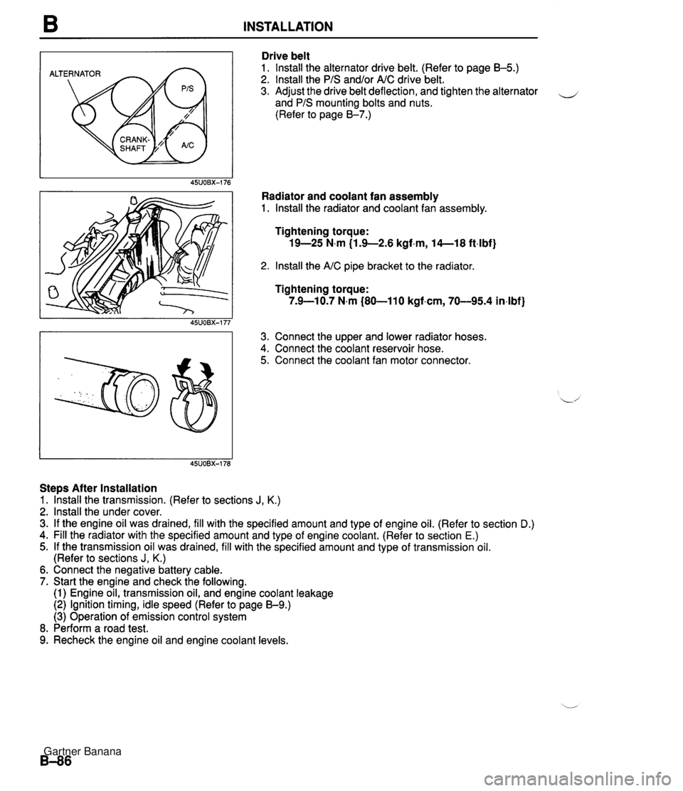
B INSTALLATION ALTERNATOR Drive belt 1. lnstall the alternator drive belt. (Refer to page B-5.) 2. lnstall the PIS and/or AIC drive belt. 3. Adjust the drive belt deflection, and tighten the alternator - and PIS mounting bolts and nuts. (Refer to page 8-7.) Radiator and coolant fan assembly 1. lnstall the radiator and coolant fan assembly. Tightening torque: 19-25 N.m (1.9-2.6 kgf.m, 14--18 ft4bf) 2. lnstall the AIC pipe bracket to the radiator Tightening torque: 7.9-10.7 N.m (80-110 kgf.cm, 70-95.4 in4bf) 3. Connect the upper and lower radiator hoses. 4. Connect the coolant reservoir hose. 5. Connect the coolant fan motor connector. Steps After Installation 1. lhstall the transmission. (Refer to sections J, K.) 2. lnstall the under cover. 3. If the engine oil was drained, fill with the specified amount and type of engine oil. (Refer to section D.) 4. Fill the radiator with the specified amount and type of engine coolant. (Refer to section E.) 5. If the transmission oil was drained, fill with the specified amount and type of transmission oil. (Refer to sections J, K.) 6. Connect the negative battery cable. 7. Start the engine and check the following. (1) Engine oil, transmission oil, and engine coolant leakage (2) Ignition timing, idle speed (Refer to page 59.) (3) Operation of emission control system 8. Perform a road test. 9. Recheck the engine oil and engine coolant levels. Gartner Banana
Page 124 of 1708

Before beginning any service procedure. refer to section T of this manual for air bag system service warnings and audio antitheft system alarm conditions . LUBRICATION SYSTEM INDEX ....................................... D- 2 ..................................... OUTLINE D- 3 ........................... SPECIFICATIONS D- 3 TROUBLESHOOTING GUIDE .................. D- 3 OIL PRESSURE .............................. D- 4 PREPARATION ............................. D- 4 INSPECTION ............................... D- 4 ENGINE OIL .................................. D- 5 INSPECTION ............................... D- 5 REPLACEMENT ............................ D- 5 OIL FILTER ................................... D- 6 REPLACEMENT ............................ D- 6 OIL COOLER ................................. D- 7 REMOVAL / INSTALLATION .................. D- 7 OIL PAN ..................................... D- 8 REMOVAL / INSTALLATION .................. D- 8 OIL PUMP .................................... D-11 DISASSEMBLY / ASSEMBLY ................. D-11 INSPECTION ............................... D-12 45UODX401 Gartner Banana
Page 125 of 1708

INDEX INDEX HYDRAULIC LASH ADJUSTER (HLA) REMOVAL / INSPECTION I INSTALLATION, SECTION B ENGINE OIL SPECIFICATION API SERVICE SG, SH (ECII) ILSAC TOTAL CAPACITY 4.0 L (4.2 US qt, 3.5 Imp qt) 1. Oil pressure 4. Oil cooler Inspection ................. page D- 4 Removal I Installation ....... page D- 7 2. Engine oil 5. Oil pan Inspection ................. page D- 5 Removal / Installation ....... page D- 8 Replacement .............. page D- 5 6. Oil pump _-' 3. Oil filter Disassembly I Assembly .... page D-11 .............. Replacement page D- 6 Inspection ................. page D-12 Gartner Banana
Page 126 of 1708

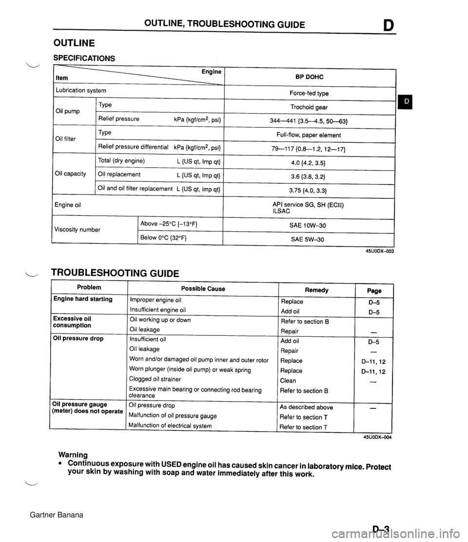
OUTLINE, TROUBLESHOOTING GUIDE D OUTLINE SPECIFICATIONS Engine BP DOHC Lubrication system Oil capacity Engine oil Force-fed type Trochoid gear 344--441 {3.5-4.5,50--63) Full-flow, paper element 79--117 {0.&1.2, 12-1 7) Oil pump Oil filter Oil and oil filter replacement L {US qt, Imp qt) API service SG, SH (ECII) l LSAC TY pe Relief pressure kPa {kgf/cm2, psi) Type Relief pressure differential kPa {kgf/cm2, psi) Total (dry engine) L (US qt, Imp qt} Oil replacement L {US qt, Imp qt} 3.75 (4.0, 3.3) 4.0 f4.2, 3.5) 3.6 (3.8,3.2) I TROUBLESHOOTING GUIDE Problem SAE 1 OW-30 SAE 5W-30 Viscosity number Engine hard starting 45UODX-003 Above -25°C (-1 3°F) Below 0°C {32"F} Excessive oil consumption Oil pressure drop Oil pressure gauge (meter) does not operate Warning Possible Cause Improper engine oil Insufficient engine oil Oil working up or down Oil leakage Insufficient oil Oil leakage Worn and/or damaged oil pump inner and outer rotor Worn plunger (inside oil pump) or weak spring Clogged oil strainer Excessive main bearing or connecting rod bearing clearance Oil pressure drop Malfunction of oil pressure gauge Malfunction of electrical system Remedy Replace Add oil Refer to section 6 Repair Add oil Repair Replace Replace Clean Refer to section B As described above Refer to section T Refer to section T Page D-5 D-5 - 0-5 - D-11,12 D-ll,12 - - 45UODX-004 Conthuous exposure with USED engine oil has caused skin cancer in laboratory mice. Protect your skin by washing with soap and water immediately after this work. Gartner Banana