engine oil MAZDA MX-5 1994 Repair Manual
[x] Cancel search | Manufacturer: MAZDA, Model Year: 1994, Model line: MX-5, Model: MAZDA MX-5 1994Pages: 1708, PDF Size: 82.34 MB
Page 157 of 1708
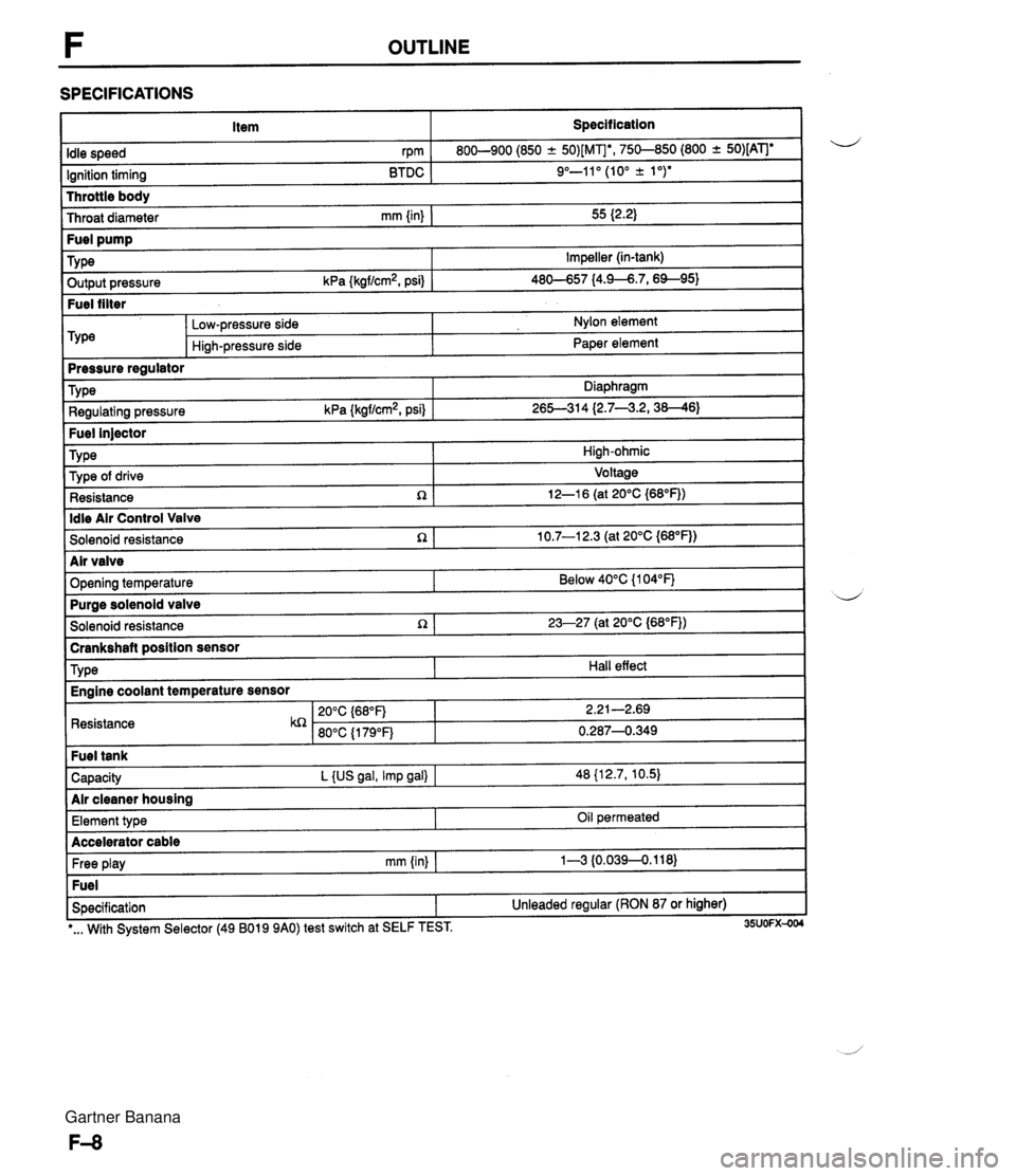
F OUTLINE SPECIFICATIONS Item Specification I Throttle body Throat diameter mm {in) I 55 I2.2) Idle speed rpm Ignition timing BTDC 800-900 (850 -+ 50)[MIb, 750-850 (800 + 50)[ATJe 9"-11" (10" k 1 ")* ~ut~~~ressure kPa {kgf/cm2, psi) 1 46-57 14.9--6.7,6%95) Fuel filter Fuel pump TY pe -- m&e regulator Impeller (in-tank) Low-pressure side Hi~h-pressure side Nylon element Paper element Fuel injector TY pe I High-ohmic Type Regulating pressure kPa {kgf/cm2, psi) Diaphragm 26S314 (2.7--3.2,38--46) ldle Air Control Valve Solenoid resistance n 1 10.7-1 2.3 (at 20°C {M°F)) Type of drive Resistance R Voltage 12-1 6 (at 20°C {68"F)) I Solenoid resistance 1 23-27 (at 20°C (68"FJ) I -- brankshaft position sensor d Air valve Opening temperature I Resistance Below 40°C {I 04°F) TY pe Capacity L {US gal, Imp gal) I 48 {12.7, 10.5) Air cleaner housing Purae solenoid valve Hall effect Engine coolant temperature sensor Free play mm (in) I 1-3 {0.0394.118) Fuel Specification 1 Unleaded regular (RON 87 or higher) Element type I I -. I *... With System Selector (49 B019 9AO) test switch at SELF TEST. 35UOFX-004 Oil permeated Accelerator cable Gartner Banana
Page 158 of 1708
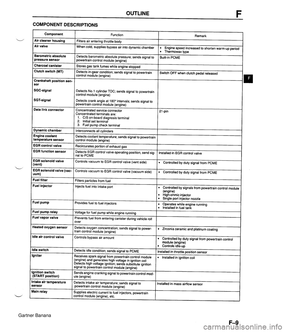
OUTLINE F COMPONENT DESCRIPTIONS Component Air cleaner housing Air valve Remark Function Filters air entering throttle body When cold, supplies bypass air into dynamicchamber w Engine speed increased to shorten warm-up period Thermowax type Barometric absolute pressure sensor Detects barometric absolute pressure; sends signal to powertrain control module (engine) 3uilt-in PCME Charcoal canister Clutch switch (MT) Stores gas tank fumes while engine stopped Detects in-gear condition: sends signal to powertrain control module (engine) --- ~witch OFF when clutch pedal released Crankshaft position sen- sor Detects No.1 cylinder TDC; sends signal to powertrain control module (engine) Detects crank angle at 180" intervals; sends signal to powertrain control module (engine) Data link connector Concentrated service connector Concentrated terminals are: 1. CIS on-board diagnosis terminal 2. Initial set terminal 3. Fuel pump check terminal Dynamic chamber Interconnects all cylinders Detects coolant temperature; sends signal to powertrain control module (engine) Recircurates oortion of exhaust aas Engine coolant temperature sensor EGR control valve lnstalled in EGR control valve EGR function sensor Detects EGR control valve operating position; send sig- nal to PCME EGR solenoid valve (vent) Controls vacuum to EGR control valve (vent side) Controlled by duty signal from PCME . - EGR solenoid valve (vac- Controls vacuum to EGR control valve (vacuum side) 0 Controlled by duty signal from PCME uum) Fuel filter Filters particles from fuel Injects fuel into intake port Fuel injector Controlled by signals from powertrain control module (engine) High-ohmic injector 0 Sinale port injector nozzle Fuel pump Provides fuel to fuel injectors 0 operates while engine running lnstalled in fuel tank Fuel pump relay Voltage for fuel pump while engine running Fuel vapor valve Prevents fuel from entering canister during vehicle roll over Heated oxygen sensor Detects oxygen concentration; sends signal to power- train control module (engine) 0 Zirconia ceramic and platinum coating ldle air control valve Controls bypass air amount Controlled by duty signal from powertrain control module (engine) Controls idle-up lnstalled in throttle position sensor lnstalled in ignition coil ldle switch Igniter Detects idle condition; sends signal to PCME Receives spark signal from powertrain control module (engine) and generates high voltage in ignition coil Detects high voltage ignition; sends substitute ignition signal to powertrain control module (engine) Ignition switch (START position) Sends engine cranking signal to powertrain control mod- ule (engine) Intake air temperature sensor Detects intake air temperature: sends signal to powertrain control module (engine) Installed in mass airflow sensor Main relay Supplies electric current to fuel injectors, powertrain control module (engine), etc. Gartner Banana
Page 164 of 1708

TROUBLESHOOTING GUIDE DIAGNOSTIC INDEX Cranks normally but will not start (No com- Engine cranks at normal speed but shows no sign of bustion) I #firingN I F-17 I No. 1 TROUBLESHOOTING ITEM Will not crank or cranks slowly -- -- Cranks normally but will not start (Partial combustion) -When engine is cold Cranks normally but will not start (Partial combustion) - After warm-up Cranks normally but hard to start - Always Cranks normally but hard to start - When engine is cold - Engine cranks at normal speed but shows partial com- bustion and will not continue to run Engine cranks at normal speed but shows partial com- bustion and will not continue to run after running and hot soaked Engine cranks at normal speed but requires excessive cranking time (more than 5 sec.) before starting Same condition as No.5 when engine is cold Restarts OK after warm-up 8 DESCRIPTION Refer to Engine Electrical System Low idle speed1Rough idle - Before warm- UP Low idle speed/Rough idle -After warm-up PAGE SECTION G Cranks normally but hard to start - After warm-up Rough idle - Always Engine speed low or engine vibrates excessively at idle during warm-up Engine runs normally at idle during warm-up but vi- brates excessively after warm-up High idle speed - After warm-up Low idle speed - When NC, PIS, or EIL ON l5 1 Engine stalls at idle - Always Engine starts normally but vibrates excessively and stalls at idle in every condition I F40 1 13 14 Same condition as No.5 after running and hot soaked Starts normally when cold Engine vibrates excessively at idle in every condition Engine idle excessive for operation mode Engine speed decreases at idle when NC, PIS, or EIL is ON 18 1 Engine stalls during start-up 1 Engine unexpectedly stops running while starting I F-45 F-26 F-27 F-34 F-36 Rough idle just after starting Idle moves up and down 16 17 l9 1 Engine stalls on deceleration I Engine unexpectedly stops running while decelerating or after deceleration Engine starts normally but vibrates excessively only just after starting Engine speed up and down periodically at idle Engine stalls at idle - Before warm-up Engine stalls at idle - After warm-up Engine stalls at idle -When AIC, PIS, or EIL running at idle when 1 20 1 ON I F-50 1 F-37 F-38 I I . . I 21 1 Engine stalls suddenly (Intermittent) I Engine intermittently stops running I F-52 Engine starts normally but vibrates excessively and stalls at idle before warm-up Engine runs normally at idle during warm-up but be- comes rouclh and stalls after warm-up F-43 F-44 24 1 Lack of power Performance is poor under load Maximum speed re- 1 duced I F-57 I Hesitates/Stumbles on acceleration Surges while cruising I I I 25 / Poor acceleration I Performance is poor while accelerating 1 F-61 I Flat spot occurs just after accelerator is depressed or mild jerking occurs during acceleration Unexpected, usually repetitive change in engine speed Knocking F-53 F-55 Runs rough on deceleration1Afterburn Abnormal combustion accompanied by audible "ping- ing" noise I F-67 I Engine runs rough while decelerating and abnormal combustion in exhaust system 1 30 1 High oil consumption I Oil consumption excessive I F-70 1 F-65 28 1 Fuel odor 29 / Exhaust sulfur smell 1 31 1 Poor fuel economy I Fuel economy unsatisfactory I F-71 I Gasoline odor in cabin Exhaust gas smells abnormal (rotten egg smell) F-69 F-70 Gartner Banana
Page 207 of 1708

TROUBLESHOOTING GUIDE INSPECTION :heck for correct ignition timing at idle page F-76 gnition timing: 10" .t lo BTDC ;heck if spark plugs are OK RBON BUILDUP PLUG GAP 1 .O-l.lmrn b.040--0.043 in} DAMAGE AND DETERIORATION DAMAGE :heck if resistance of high-tension leads are OK lesistance: 16 k!2 per 1 m (3.28 ft) :heck if resistance of ignition coil is OK Section G lesistance (at 20°C (66°F)): Secondary coil ... 8.7-12.9 'heck for correct engine compression Section B ngine compression: 1,255483 kPa (12.8-9.0 kgf/cm2, 182-128 psiE.300 rpm Yes No Yes No - Yes Yes No - Yes - No ACTION Check if ignition timing advances when accelerating s, If advances, go to next step +, If no advance, replace PCME terminal voltages page F-143 Adjust page F-76 Go to next step Repair, clean, or replace us Section G Go to next step Replace w Section G Go to next step Replace Section G 30 to next step Zheck engine condition w Section B D Worn piston, piston rings or cylinder wall D Defective cylinder head gasket Distorted cylinder head Improper valve seating B Valve sticking in guide Gartner Banana
Page 211 of 1708
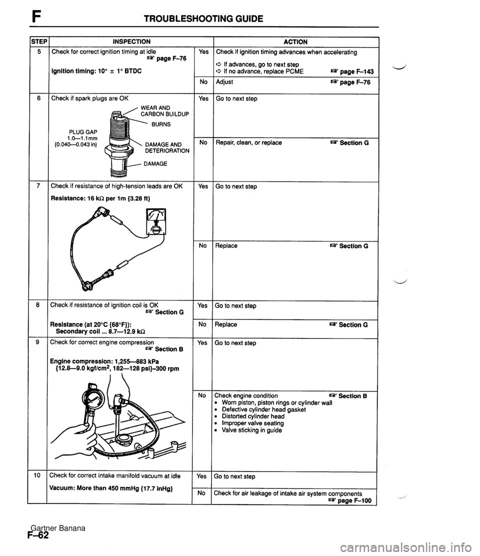
TROUBLESHOOTING GUIDE INSPECTION Check for correct ignition timing at idle t@= page F-76 Ignition timing: 10" +. lo BTDC Check if spark plugs are OK WEAR AND CARBON BUILDUP BURNS PLUG GAP 1 .+I .I mm (0.04C-O.043 in) DAMAGE AND DETERIORATION DAMAGE Check if resistance of high-tension leads are OK Resistance: 16 kR per lm {3.28 ft} Check if resistance of ignition coil is OK Section G Resistance (at 20°C {68"F)): Secondary coil ... 8.7-12.9 kC2 Check for correct engine compression Section 8 Engine compression: 1,255-883 kPa (12.8-9.0 kgf/cm2, 182-128 psi)-300 rpm :heck for correct intake manifold vacuum at idle Vacuum: More than 450 mmHg (17.7 inHg) - Yes - No Yes - No - Yes - No - Yes - No - Yes - No - Yes ACTION Check if ignition timing advances when accelerating o If advances, go to next step o If no advance, replace PCME page F-143 Adjust page F-76 Go to next step Repair, clean, or replace Ojp Section G Go to next step ~eplace as? Section G Go to next step Replace Section G - -- Go to next step :heck engine condition I@= Section B B Worn piston, piston rings or cylinder wall B Defective cylinder head gasket B Distorted cylinder head B Improper valve seating B Valve sticking in guide Check for air leakage of intake air system components as? page F-1 00 Gartner Banana
Page 219 of 1708
![MAZDA MX-5 1994 Repair Manual F TROUBLESHOOTING GUIDE I [TROUBLESHOOTING HINTS] Hinh sulfur content fuel used 29 ISTEP l INSPECTION I ACTION I EXHAUST SULFUR SMELL I 1 I Chanae fuel to another brand I DESCRIPTION I Exhaust gas sme MAZDA MX-5 1994 Repair Manual F TROUBLESHOOTING GUIDE I [TROUBLESHOOTING HINTS] Hinh sulfur content fuel used 29 ISTEP l INSPECTION I ACTION I EXHAUST SULFUR SMELL I 1 I Chanae fuel to another brand I DESCRIPTION I Exhaust gas sme](/img/28/57072/w960_57072-218.png)
F TROUBLESHOOTING GUIDE I [TROUBLESHOOTING HINTS] Hinh sulfur content fuel used 29 ISTEP l INSPECTION I ACTION I EXHAUST SULFUR SMELL I 1 I Chanae fuel to another brand I DESCRIPTION I Exhaust gas smells abnormal (Rotten egg smell) 30 I HIGH OIL CONSUMPTION TROUBLESHOOTING HINTS] D PCV system malfunction ne malfunction (Oil working up, working down, or leakage) INSPECTION Check if PCV hose, ventilation hose or their attach- ing nipples are separated, damaged, clogged, or restricted L@? page F-130 Check if air pressure or oil is present at ventilation hose VENTILATION Check if vacuum is felt at PCV valve at idle page F-130 Yes - No - Yes No - Yes ACTION Repair or replace e page F-122 Go to next step Go to next step Check engine condition Oil leakage Worn valve seal Worn valve stem Worn valve guide Section B Check engine condition Section B Worn piston ring groove Stuck piston ring Worn piston or cylinder Replace PCV valve page F-130 Gartner Banana
Page 224 of 1708
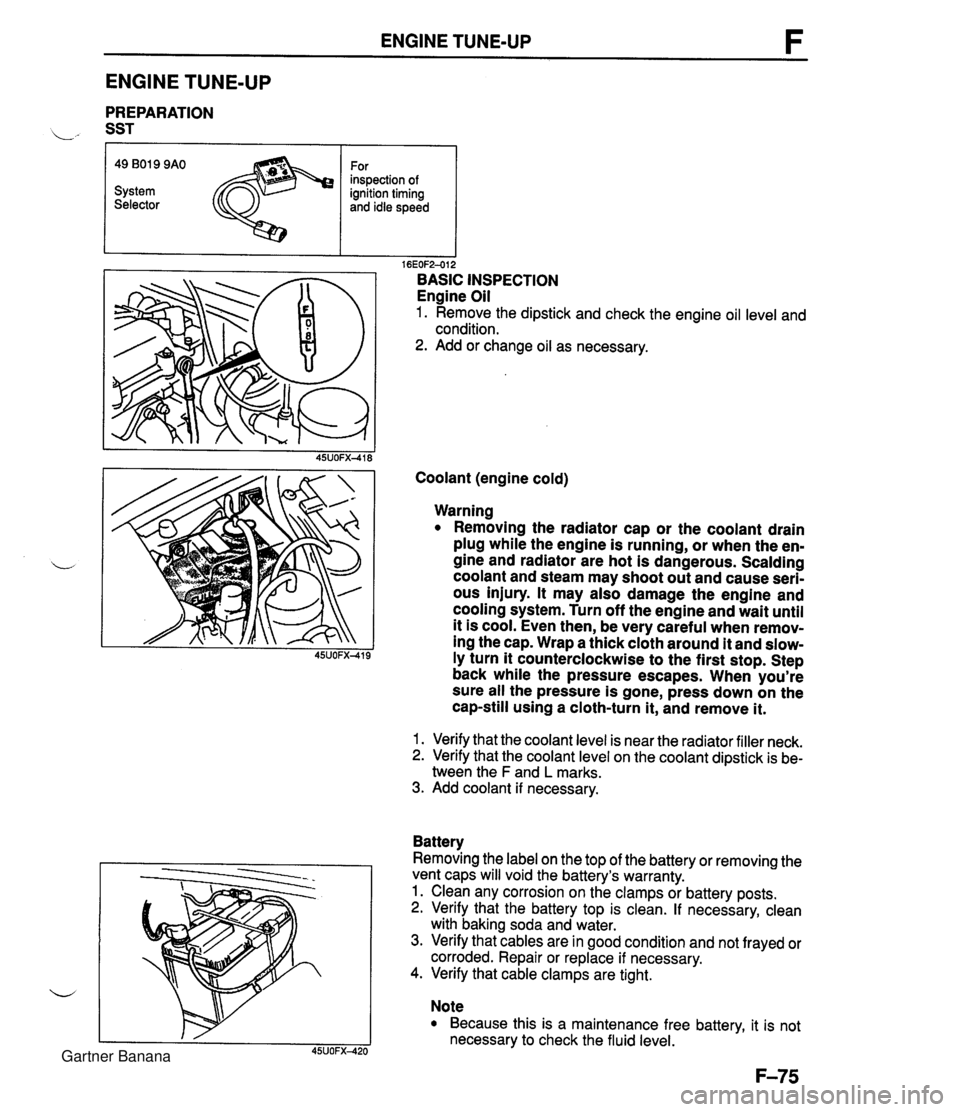
ENGINE TUNE-UP ENGINE TUNE-UP PREPARATION L" SST r I I 16EOF2-012 BASIC INSPECTION Engine Oil 1. Remove the dipstick and check the engine oil level and condition. 2. Add or change oil as necessary. 49 B019 9AO System Selector Coolant (engine cold) For inspection of ignition timing and idle speed Warning Removing the radiator cap or the coolant drain plug while the engine is running, or when the en- gine and radiator are hot is dangerous. Scalding coolant and steam may shoot out and cause seri- ous injury. It may also damage the engine and cooling system. Turn off the engine and wait until it is cool. Even then, be very careful when remov- ing the cap. Wrap a thick cloth around it and slow- ly turn it counterclockwise to the first stop. Step back while the pressure escapes. When you're sure all the pressure is gone, press down on the cap-still using a cloth-turn it, and remove it. 1. Verify that the coolant level is near the radiator filler neck. 2. Verify that the coolant level on the coolant dipstick is be- tween the F and L marks. 3. Add coolant if necessary. Battery Removing the label on the top of the battery or removing the vent caps will void the battery's warranty. 1. Clean any corrosion on the clamps or battery posts. 2. Verify that the battery top is clean. If necessary, clean with baking soda and water. 3. Verify that cables are in good condition and not frayed or corroded. Repair or replace if necessary. 4. Verify that cable clamps are tight. Note Because this is a maintenance free battery, it is not necessary to check the fluid level. Gartner Banana
Page 225 of 1708
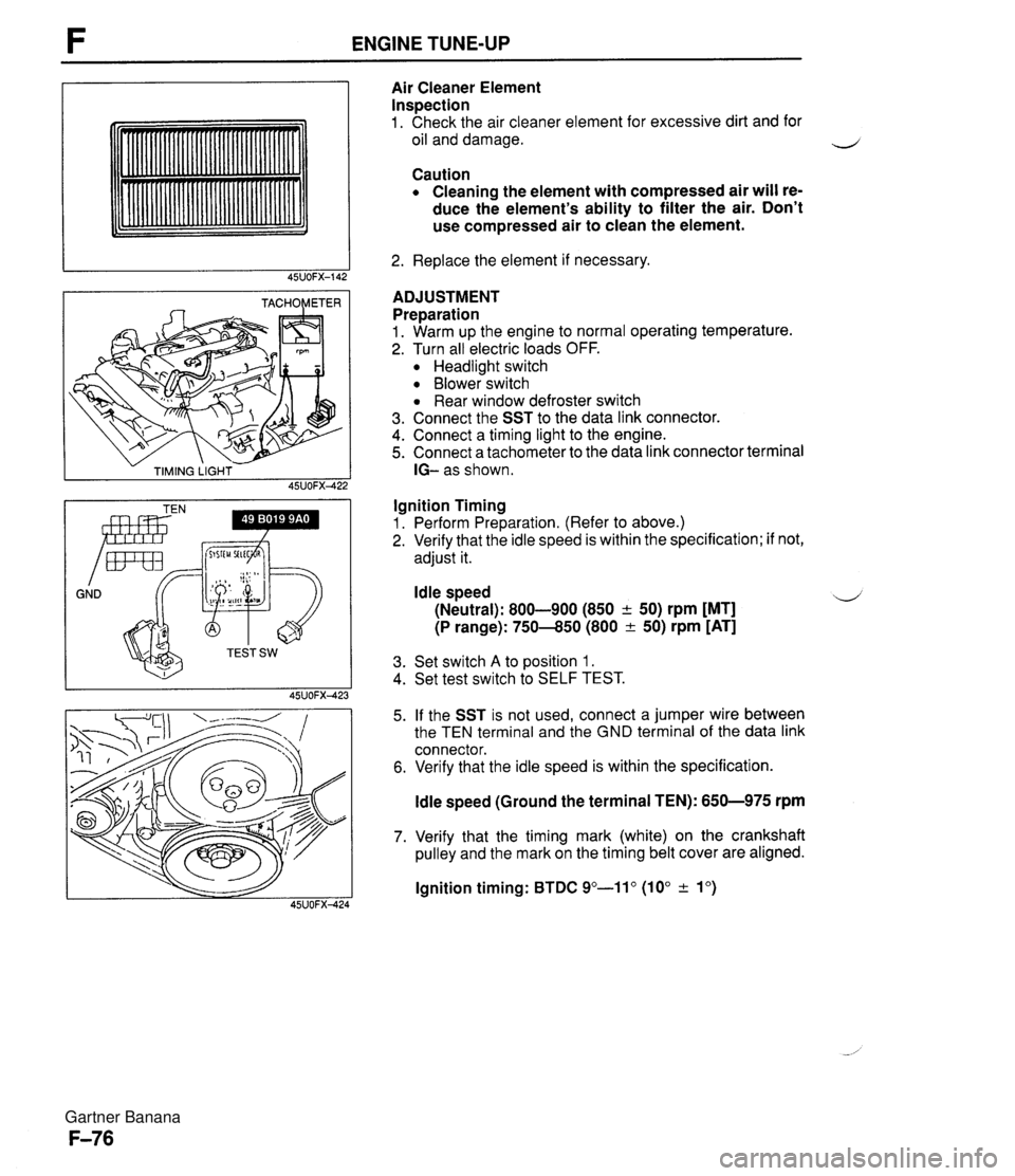
ENGINE TUNE-UP - TIMING LIGHT - 45UOFX422 GND Irnr Air Cleaner Element Inspection 1. Check the air cleaner element for excessive dirt and for oil and damage. Caution Cleaning the element with compressed air will re- duce the element's ability to filter the air. Don't use compressed air to clean the element. 2. Replace the element if necessary. ADJUSTMENT Preparation 1. Warm up the engine to normal operating temperature. 2. Turn all electric loads OFF. Headlight switch Blower switch Rear window defroster switch 3. Connect the SST to the data link connector. 4. Connect a timing light to the engine. 5. Connect a tachometer to the data link connector terminal IG- as shown. Ignition Timing 1. Perform Preparation. (Refer to above.) 2. Verify that the idle speed is within the specification; if not, adjust it. Idle speed 4 (Neutral): 800-900 (850 + 50) rpm [MT] (P range): 750-850 (800 & 50) rpm [AT] 3. Set switch A to position 1. 4. Set test switch to SELF TEST. 5. If the SST is not used, connect a jumper wire between the TEN terminal and the GND terminal of the data link connector. 6. Verify that the idle speed is within the specification. ldle speed (Ground the terminal TEN): 650-975 rpm 7. Verify that the timing mark (white) on the crankshaft pulley and the mark on the timing belt cover are aligned. lgnition timing: BTDC 9"-11" (10" & lo) Gartner Banana
Page 226 of 1708
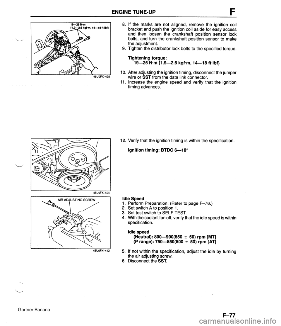
ENGINE TUNE-UP 8. If the marks are not aligned, remove the ignition coil bracket and push the ignition coil aside for easy access and then loosen the crankshaft position sensor lock bolts, and turn the crankshaft position sensor to make the adjustment. 9. Tighten the distributor lock bolts to the specified torque. Tightening torque: 19-25 N-m (1.9-2.6 kgfem, 14--18 ftqlbf) 10. After adjusting the ignition timing, disconnect the jumper wire or SST from the data link connector. 11. Increase the engine speed and verify that the ignition timing advances. 12. Verify that the ignition timing is within the specification. Ignition timing: BTDC 6-18' ldle Speed 1. Perform Preparation. (Refer to page F-76.) 2. Set switch A to position 1. 3. Set test switch to SELF TEST. 4. With the coolant fan off, verify that the idle speed is within specification. ldle speed (Neutral): 800-900(850 + 50) rpm [MT] (P range): 750--850(800 -c 50) rpm [AT] 5. If not within the specification, adjust the idle by turning the air adjusting screw. 6. Disconnect the SST. Gartner Banana
Page 270 of 1708
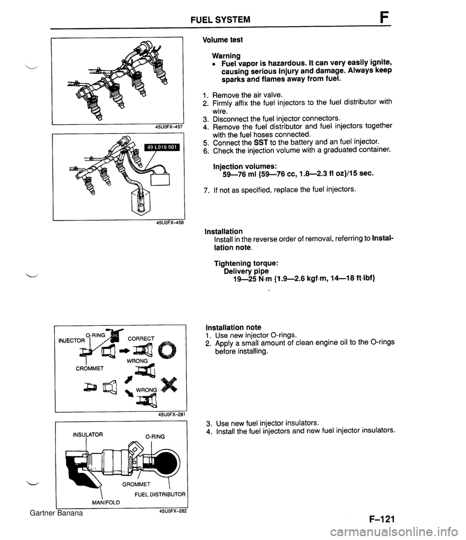
FUEL SYSTEM Volume test Warning Fuel vapor is hazardous. It can very easily ignite, causing serious injury and damage. Always keep sparks and flames away from fuel. 1. Remove the air valve. 2. Firmly affix the fuel injectors to the fuel distributor with wire. 3. Disconnect the fuel injector connectors. 4. Remove the fuel distributor and fuel injectors together with the fuel hoses connected. 5. Connect the SST to the battery and an fuel injector. 6. Check the injection volume with a graduated container. Injection volumes: 59-76 ml (59-76 cc, 1.8-2.3 fl oz}/15 sec. 7. If not as specified, replace the fuel injectors. lnstallation Install in the reverse order of removal, referring to Instal- lation note. Tightening torque: Delivery pipe 19-25 N.m (1 .%2.6 kgfm, 14--18 ft4bf) FUEL DISTRIBUTOR MANIFOLD C 45UOFX-282 Installation note 1. Use new injector O-rings. 2. Apply a small amount of clean engine oil to the O-rings before installing. 45UOFX-281 INSULATOR O-RING 3. Use new fuel injector insulators. 4. Install the fuel injectors and new fuel injector insulators. Gartner Banana