no spark MAZDA PROTEGE 1992 User Guide
[x] Cancel search | Manufacturer: MAZDA, Model Year: 1992, Model line: PROTEGE, Model: MAZDA PROTEGE 1992Pages: 1164, PDF Size: 81.9 MB
Page 142 of 1164

B2 COMPRESSION
COMPRESSION
If the engine exhibits low power, poor fuel economy, or poor idle, check the following:
1, Ignition system (Refer to Section G.)
2. Compression
3. Fuel system (Refer to Section F.)
23UOB2-013
13UOl32.004
2311087-014
-_
B2-10
2311082-012
INSPECTION
1. Check that the battery is fully charged. Recharge it if neces-
sary. (Refer to Section G.)
2. Warm up the engine to normal operating temperature.
3. Turn the engine OFF.
4. Remove all spark plugs.
5, Disconnect the ignition coil connector.
6. Connect a compression gauge to the No.1 spark plug hole.
7. Fully depress the accelerator pedal and crank the engine.
8. Record the maximum gauge reading.
9. Check each cylinder.
Compression:
1,256 kPa (12.6 kg/cm’, 182 psi)-300 rpm
Minimum:
883 kPa (9.0 kg/cm2, 128 psi)-300 rpm
Max. difference between cylinders:
196 kPa (2.0 kg/cm2, 28 psi)
10. If the compression in one or more cylinders is low, pour a
small amount of engine oil into the cylinder and recheck
the compression.
(1) If the compression increases, the piston, piston rings,
or cylinder wall may be worn.
(2) If the compression stays low, the valve may be stuck
or seating improperly.
(3) If the compression in adjacent cylinders stays low, the
cylinder head gasket may be defective or the cylinder
head distorted.
Il. Connect the ignition coil connector.
12. Install the spark plugs.
05UOBX-020
Tightening torque:
15-23 N*m (1.5-2.3 m-kg, 11-17 ft-lb)
Page 144 of 1164

B2 ON-VEHICLE MAINTENANCE
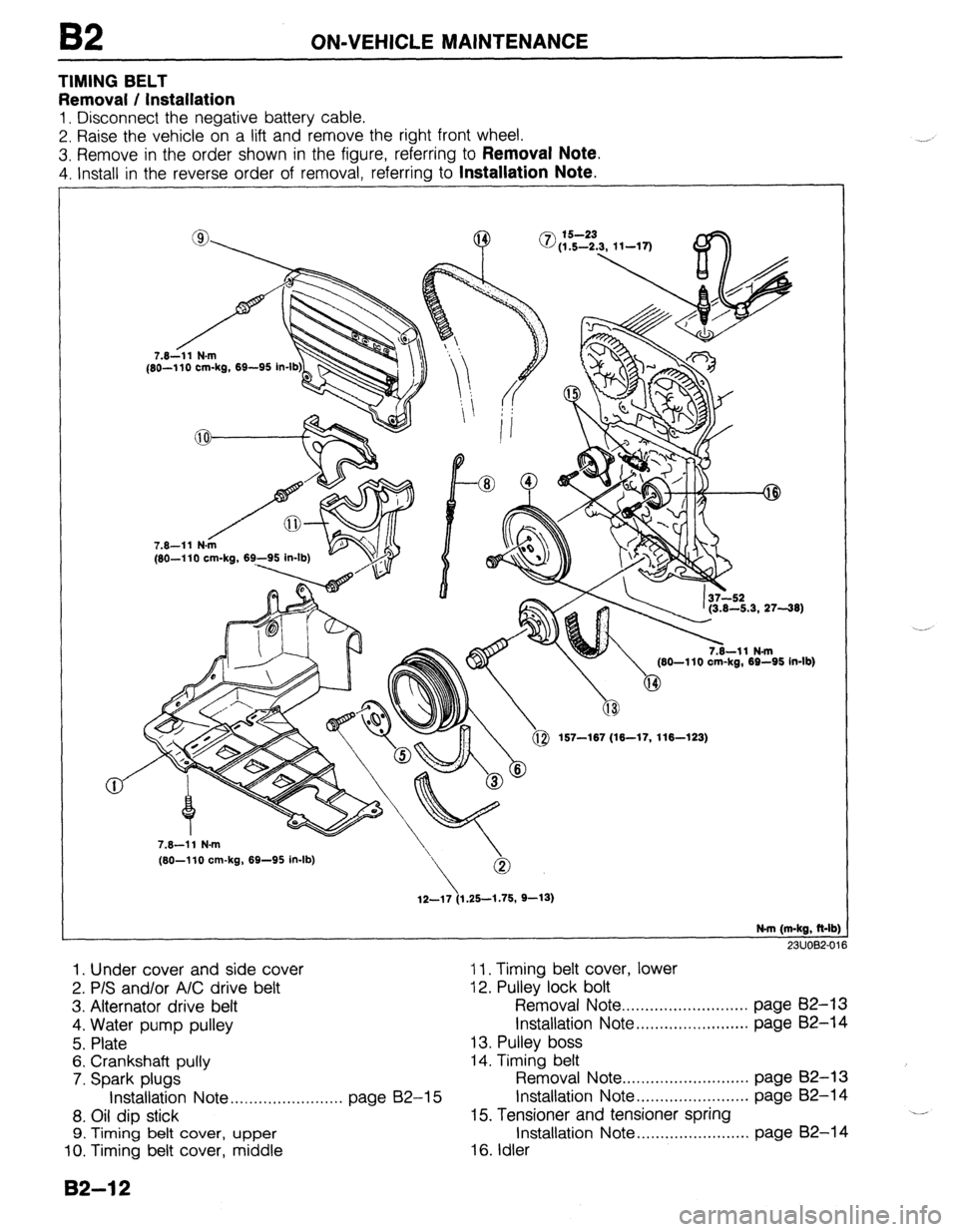
TIMING BELT
Removal / Installation
1. Disconnect the negative battery cable.
2. Raise the vehicle on a lift and remove the right front wheel.
3. Remove in the order shown in the figure, referring to
Removal Note.
4. Install in the reverse order of removal, referring to Installation Note.
/ 7.8-11 N.m
(80-l 10 Cm-kg, 69-95 in-lb
1p1\ ’ (3.8-6.3, 2738)
, (80-l 10 cm-kg, 69-95 in-lb)
167--187 (X-17, 116-123)
/ 7.8--11 N-m
(80-110 MI-kg,
7.8-11 N-m
\-
(80-110 Cm-kg, 69-95 in-lb)
12-17 (1.25-1.75, 9-13)
N-m (m-kg, &lb
23UOl32-0
1. Under cover and side cover 11. Timing belt cover, lower
2. P/S and/or A/C drive belt 12. Pulley lock bolt
3. Alternator drive belt Removal Note . . ..*..........*.*......... page 82-13
4. Water pump pulley Installation Note . . . . . . . . . . . . . . . . . . . . . . . . page B2-14
5. Plate 13. Pulley boss
6. Crankshaft pully 14. Timing belt
7. Spark plugs Removal Note . . . . . . . . . . . . . . . . . . . . . . . . . . . page 62-13
Installation Note . . . . . . . . . . . . . . . . . . . . . . . . page 62-15 Installation Note . . . . . . . . . . . . . . . . . . . . . . . . page B2-14
8. Oil dip stick 15. Tensioner and tensioner spring ..l
9. Timing belt cover, upper Installation Note ..,..................... page B2-14
10. Timing belt cover, middle 16. Idler
B2-12
Page 147 of 1164

ON-VEHICLE MAINTENANCE
13EOB2-015
DEFLECTION CHECKING POINT
13EOE2-011
23UOB2-017
23UOB2-018
Steps After Installation
1. Connect the negative battery cable.
2. Start the engine and check as follows:
l Ignition timing. (Refer to page B2-8.) 10. Loosen the tensioner lock bolt to apply spring tension to
the timing belt.
11. Tighten the tensioner lock bolt.
Tightening torque:
37-52 Narn (3.8-5.3 m-kg, 27-38 ft-lb)
12. Install the pulley boss and pulley lock bolt.
13. Turn the crankshaft 2 and 116 turns clockwise and verify
that the timing marks are correctly aligned.
14. Measure the timing belt deflection by applying moderate
pressure (98 N,
10 kg, 22 lb) midway between the cam-
shaft pulleys.
If the deflection is not correct, repeat from Step 10 above.
Deflection:
9.0-11.5mm (0.35-0.45 In) at 98 N (10 kg, 22 lb)
Spark plug
1. Install the spark plugs.
Tightening torque:
15-23 Nern (1.5-2.3 m-kg, 11-17 ft-lb)
Pulley lock bolt
1, Hold the crankshaft with the SST and tighten the pulley lock
bolt.
Tightening torque:
157-187 N*rn (18-17 m-kg, 118-123 ft-lb)
23UOB2-019
82-l 5
Page 148 of 1164

82 ON-VEHICLE MAINTENANCE
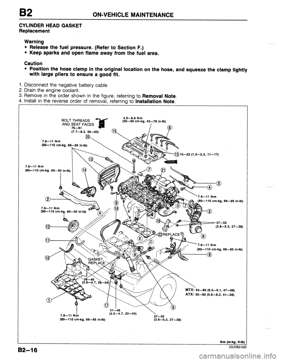
CYLINDER HEAD GASKET
Replacement
Warning
l Release the fuel pressure. (Refer to Section F.)
l Keep sparks and open flame away from the fuel area.
Caution
l Position the hose clamp in the original location on the hose, and squeeze the clamp lightly
with large pliers to ensure a good fit.
1. Disconnect the negative battery cable.
2. Drain the engine coolant.
3. Remove in the order shown in the figure, referring to
Removal Note.
4. install in the reverse order of removal, referrina to Installation Note.
BOLT THREADS ?&d 4.9-8.8 N.m
fsn-an om.h 41-‘71( ir
AND SEAT FACES ,-- -- -... ..=, _” . _ ..I-lb)
78-81 - /
(7.7-8.3, 58-60)
7.8-11 N.m
(80-l 10 cm-ka, 69-95
, . . . . . . (80-l 10 cm-kg, 69-9: in-lb) (j-$15-23 (1.5-2.3, 11-17)
82-l 6
7.8-11 N.m
(80-110 cm-k?, 69-95 In-lb) 180-110 cm-ka. 69-95 in-lb
-37-52
(3.8-5.3, 27-38)
’
nl MTX:?64-69 (6.6-9.1,
PTX: 55-60 (6.6-8.2, 69-95 in. .Ib)
47-86)
41-69)
7.8-11 N./n (3.2-4.7, 23-34)
37-52
(80-110 cm-kg, 69-95 in-lb) (3.8-5.3, 27-38)
N-m (m-kg, N-lb)
^^. .^_^ __
Page 149 of 1164

ON-VEHICLE MAINTENANCE B2
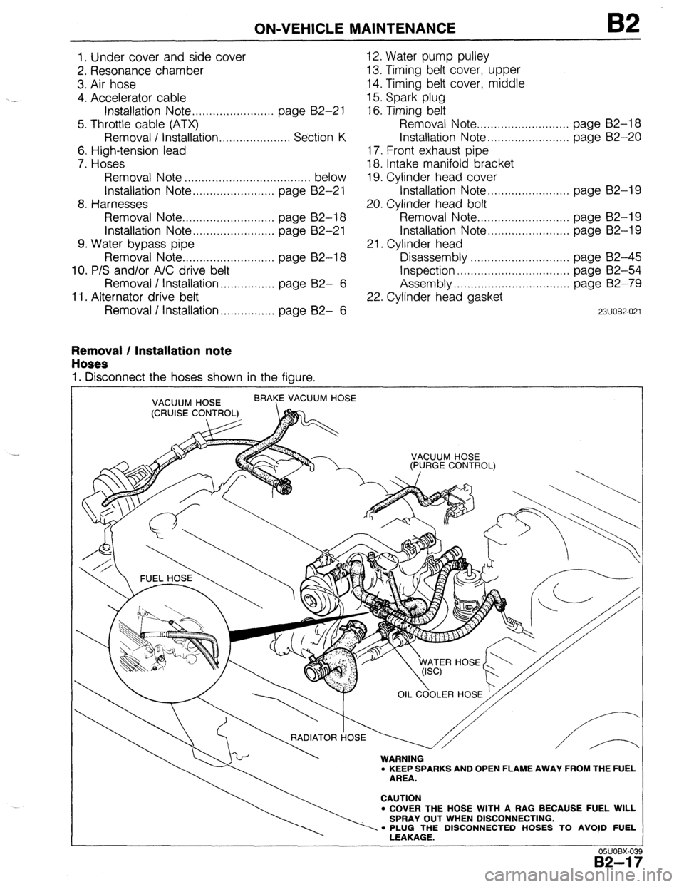
1. Under cover and side cover
2. Resonance chamber
3. Air hose
4. Accelerator cable
Installation Note . . . . . . . . . . . . . . . . . . . . . . . . page B2-21
5. Throttle cable (ATX)
Removal I Installation . . . . . . . . . . . . . . . . . . . . . Section K
6. High-tension lead
7. Hoses
Removal Note . . . . . . . . . . . . . . . . . . . . . . . . . . . . . . . . . . . . . below
Installation Note . . . . . . . . . . . . . . . . . . . . . . . . page 82-21
8. Harnesses
Removal Note . . . . . . . . . . . . . . . . . . . . . . . . . . . page B2-18
Installation Note . . . . . . . . . . . . . . . . . . . . . . . . page 82-21
9. Water bypass pipe
Removal Note . . . . . . . . . . . . . . . . . . . . . . . . . . . page B2-18
10. P/S and/or A/C drive belt
Removal / Installation . . . . . . . . . . . . . . . . page B2- 6
11. Alternator drive belt
Removal / Installation . . . . . . . . . . . . . . . . page B2- 6 12. Water pump pulley
13. Timing belt cover, upper
14. Timing belt cover, middle
15. Spark plug
16. Timing belt
Removal Note . . . . . . . . . . . . . . . . . . . . . . . . . . . page 82-l 8
Installation Note . . . . . . . . . . . . . . . . . . . . . . . . page B2-20
17. Front exhaust pipe
18. Intake manifold bracket
19. Cylinder head cover
Installation Note . . . . . . . . . . . . . . . . . . . . . . . . page 82-19
20. Cylinder head bolt
Removal Note . . . . . . . . . . . . . . . . . . . . . . . . . . . page B2-19
Installation Note . . . . . . . . . . . . . . . . . . . . . . . . page B2-19
21. Cylinder head
Disassembly . . . . . . . . . . . , . . . . . . . . . . . . . page B2-45
Inspection . . . . . . . . . . . . . . . . . . . . . . . . . . . . . . . . . page B2-54
Assembly . . . . . . . . . . . . . . . . . . . . . . . . . . . . . . . . page 82-79
22. Cylinder head gasket
23UOB2-021
Removal / Installation note
Hoses
1. Disconnect the hoses shown in the figure.
VACUUM HOSE BRAYE VACUUM HOSE
‘-;:I::------. CAUT’oN
l COVER THE HOSE WITH A RAG BECAUSE FUEL WILL
SPRAY OUT WHEN DISCONNECTING.
- PLUG THE DISCONNECTED HOSES TO AVO!D FUEL
LEAKAGE.
OWOBX-03
82-l i
Page 150 of 1164

B2 ON-VEHICLE MAINTENANCE
Harnesses
1, Disconnect the harness connectors shown in the figure.
.~
DISTRBUTOR
GRqUND
B2-18
Water bypass pipe
1. Remove the transaxle installation bolt as shown in the figure.
2. Remove the exhaust manifold nut as shown in the figure.
3. Remove the water bypass pipe from the cylinder head as-
sembly.
Timing belt
Note
l Remove all spark plugs for easier rotation of the
crankshaft.
1. Turn the crankshaft and align the marks.
Page 154 of 1164

B2 ON-VEHICLE MAINTENANCE
HLA
Removal / Installation
1. Disconnect the negative battery cable.
2. Remove in the order shown in the figure, referring to
Removal Note.
3. install in the reverse order of removal, referring to Installation Note --- ----- -__ __-- ,‘.
11.3-14.2 N.m
(1.15-1.45 m-\g, 100-126 in-lb)
49-61
(5.0~6.2,-36-45)
4.9-6.6 N.m
(50-90 cm-kg, 43-76 in-lb)
7.6All N-m
(80-110 cm-kg, 69-95 in-lb) 1 Q’-25
(1.9-2.6, 14-19)
N.m (m-kg, ft-lb)
0311082-03
1. High-tension lead
10. Cylinder head cover
2. Distributor
Installation Note..
....................
Installation Note.. ......................
page 62-25
11. Camshaft pulley
3. P/S and/or A/C drive belt
Removal note ..........................
Removal / Installation..
.............. page E32-
6
Installation Note .......................
4. Alternator drive belt
12. Seal plate
Removal / Installation
......... . ...... page B2- 6
13. Camshaft
5. Water pump pulley
Removal Note.. ........................
6. Timing belt cover, upper
Installation Note.. .....................
7. Timing belt cover, middle
14. HLA
8. Spark plug
Removal note ..........................
9. Timing belt
Installation
Note.. .....................
Removal Note.. .........................
page B2-18 Inspection
................................
Installation Note.. ......................
page B2-20
7
page 62-19
page 82-23
page 82-24
page B2-23
page 62-23
page B2-23
page B2-23 ‘--’
page 82-60
82-22
Page 165 of 1164

REMOVAL
Step 3
1. Disconnect the hoses shown in the figure.
J”“DC-” I I
1. Fuel hose
3. Brake vacuum hose
Removal
Note . . . . . . . . . . . . . . . . . . . . . . . . . . . . . . . . . . . . .
below
4. Vacuum hose (Purge control)
2. Heater hose
Removal Note . . . . . . . . . . . . . , . . . . . . . . . . . .
05UOBX-078
0311082-052
. . . . .
below 5. Vacuum hose (Cruise control)
Removal note
Fuel hose
Warning
l Keep sparks and open flame away from the fuel
area.
Caution
l Cover the hose with a rag because fuel will spray
out when disconnecting.
l Plug the disconnected hoses to avoid fuel leakage.
1. Disconnect the fuel hoses.
Heater hose
Caution
l Heater hose joint has O-rings and spacer.
l Do not lose them when removing.
1. Push the heater hose retainer and remove the heater hose.
82-33
Page 174 of 1164

B2 DISASSEMBLY
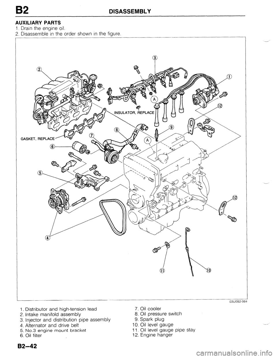
AUXILIARY PARTS
1, Drain the engine oil.
2. Disassemble in the order shown in the figure
GASKET, REPLACE ..______-.
-___ -
03UOB2-064
1. Distributor and high-tension lead 7. Oil cooler
2. Intake manifold assembly 8. Oil pressure switch
3. Injector and distribution pipe assembly 9. Spark plug
4. Alternator and drive belt 10. Oil level gauge
5. No.3 engine mount bracket 11. Oil level gauge pipe stay
6. Oil filter 12. Engine hanger
82-42
Page 220 of 1164

82 ASSEMBLY
Oil Level Gauge Pipe Stay
1. Install the oil level gauge pipe stay.
Tightening torque:
7.8-l 1 N-m (80-l 10 cm-kg, 89-95 in-lb)
Oil Level Gauge
1. Install the level gauge.
Spark Plug
1, Install the spark plugs.
Tightening torque:
15-23 N*m (1.5-2.3 m-kg, 11-17 ft-lb)
Oil Pressure Switch
1. Install the oil pressure switch.
Tightening torque:
12-18 N-m (120-180 cm-kg, 104-156 in-lb)
Oil Cooler
1. Remove all foreign material from the oil cooler mounting
surface.
2. Apply a small amount of clean engine oil to the rubber seal
of the oil cooler.
3. Install the oil cooler with paint mark (white) facing up.
4. Tighten the oil cooler lock nut.
Tightening torque:
29-39 N.m (3.0-4.0 m-kg, 22-29 ft-lb)
5. Connect the harness to oil pressure switch.
Oil Filter
1. Remove all foreign material from the oil filter mounting
surface.
2. Apply a small amount of clean engine oil to the rubber seal
of the oil filter.
3. Install the oil filter and tighten it by hand until the rubber
seal contacts the base.
4. Tighten the filter 1 and 116 turns with a filter wrench. --_