no spark MAZDA PROTEGE 1992 Service Manual
[x] Cancel search | Manufacturer: MAZDA, Model Year: 1992, Model line: PROTEGE, Model: MAZDA PROTEGE 1992Pages: 1164, PDF Size: 81.9 MB
Page 456 of 1164

G IGNITION SYSTEM
TROUBLESHOOTING
iTEP
INSPECTION
ACTION
1
Check if MIL illuminates when engine is running Yes Check for malfunction code number
and perform troubleshooting (TEN ter-
minal grounded) c7 Section F
No Go to next step
2 Drsconnect high-tension lead from distributor and
Yes
check for strong blue spark while cranking en-
l Check distributor cap and rotor v page G-22
gine * Check high-tension lead
KP page G-19 c7 page G-17
+ Ignition system normal
No
Go to next step
3 Check if resistance of ignition coil is OK
Yes
Go to next step ~7
page G-19
Specification (at 20°C [66”9):
Primary coil winding: 0.81-0.99Q No
Replace ignition coil
Secondary coil winding: IO-16 kQ
-i
Check if resistance of high-tension leads is OK Yes Go to next step
D= page G-17
Specification: 16 kQ per 1 m (3.28 ft)
No Replace high-tension lead
5 Check if igniter is OK
m- page G-23 Yes
Replace ECU
No
Replace igniter
03UOGX-03
G-16
Page 458 of 1164

G IGNITION SYSTEM
-.-.. .----___ 03UOGX-042
03UOGX-04
--.---- J
03UOGX-044
WEAR AND CARBON
/
c- -BURNT
PLUG GAP
L--
c
DAMAGE AND
,llllll....*llll,lllf DETERIORATIOF
; -,DAMAGE
03UOGX.04
G-18
SPARKPLUGS
Removal / Installation
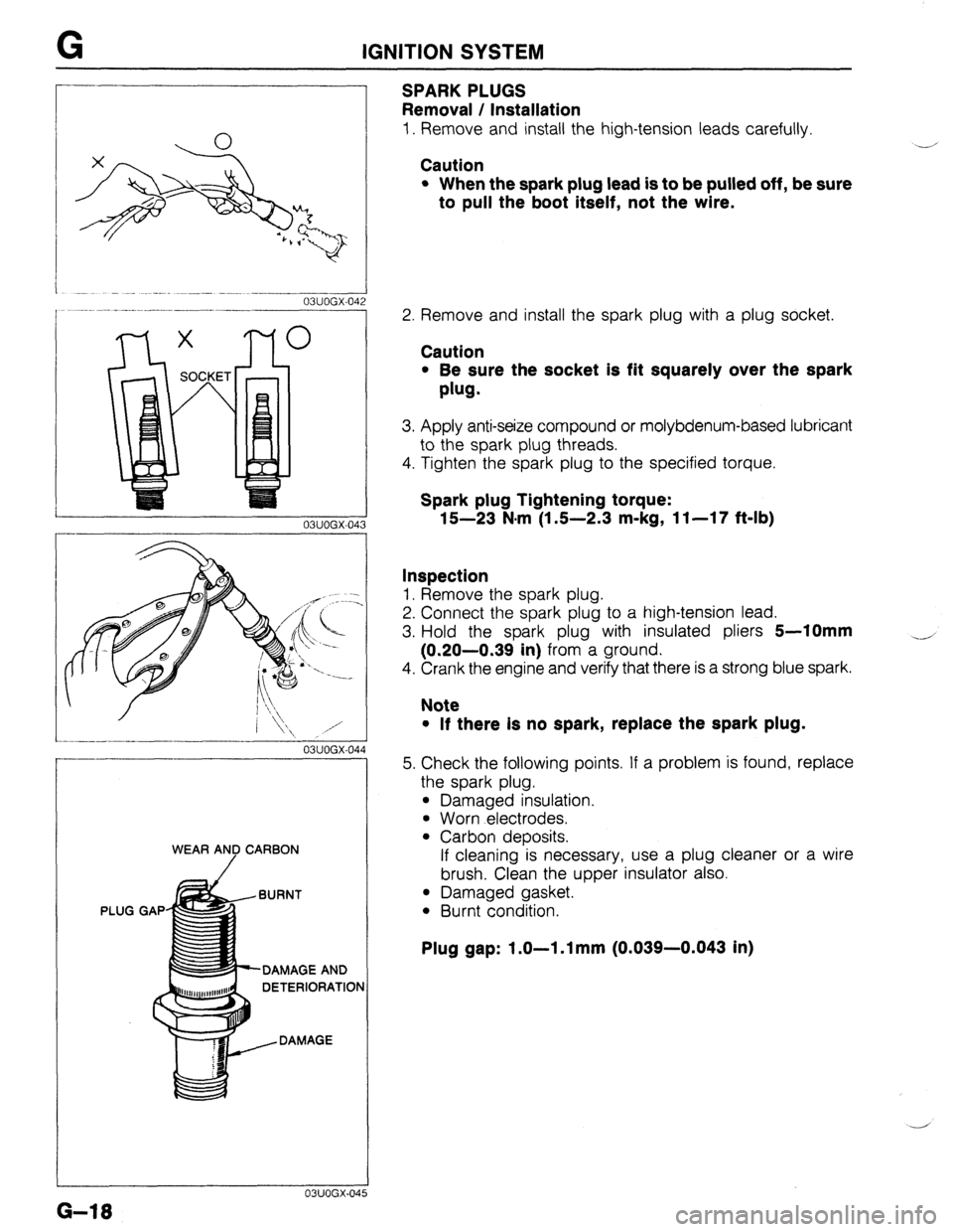
1. Remove and install the high-tension leads carefully.
Caution
l When the spark plug lead is to be pulled off, be sure
to pull the boot itself, not the wire.
Y’
2. Remove and install the spark plug with a plug socket.
Caution
l Be sure the socket is fit squarely over the spark
plug.
3. Apply anti-seize compound or molybdenum-based lubricant
to the spark plug threads.
4. Tighten the spark plug to the specified torque.
Spark plug Tightening torque:
15-23 N.m (1 S-2.3 m-kg, 11-17 f&lb)
Inspection
1. Remove the spark plug.
2. Connect the spark plug to a high-tension lead.
3. Hold the spark plug with insulated pliers
5-10mm
(0.20-0.39 in) from a ground.
4. Crank the engine and verify that there is a strong blue spark.
4
Note
l If there Is no spark, replace the spark plug.
5. Check the following points. If a problem is found, replace
the spark plug.
l Damaged insulation.
l Worn electrodes.
l Carbon deposits.
If cleaning is necessary, use a plug cleaner or a wire
brush. Clean the upper insulator also.
l Damaged gasket.
l Burnt condition.
Plug gap: 1.0-l .l mm (0.039-0.043 in)
Page 459 of 1164

IGNITION SYSTEM . . . ._,
03UOGX-04
Lszl /
P
0 V
- 23UOGX-OC
03UOGX-048
03UOGX-04
03UOGX-0%
IGNITION COIL
Inspection
Spark test
1. Disconnect the high-tension lead from the distributor.
2. Hold it with insulated pliers 5-l
Omm (0.20-0.39 in) from
a ground.
3. Crank the engine and verify that a strong blue spark is
visible.
4. If there is no spark, disconnect the connector from the igni-
tion coil and check for voltage at the positive (+) terminal
of the connector with the ignition switch in the ON position.
Specification: Battery voltage
5. If there is no voltage, check the main fuse, ignition switch,
and wire harness.
Primary coil winding
1. Use an ohmmeter and measure resistance of the primary
coil winding. If not within specification, replace the coil.
Prlmary coil resistance: 0.81-0.99112 (at 2O*C [88*F])
Secondary coil winding
1. Use an ohmmeter and measure resistance of the secon-
dary coil winding. If not within specification replace the coil.
Secondary coil resistance: lo-18 kQ (at 20°C [68*F])
Insulation of case
1. Use a 500V megger tester to measure the insulation resis-
tance between each terminal and the case.
Speclficatlon: 10 MS1 min.
G-19
Page 460 of 1164

G IGNITION SYSTEM
I
03UOGX~051
03UOGX-052
DISTRIBUTOR
Spark Test
1. Disconnect the high-tension lead from each spark plug.
2. Hold each insulator with pliers
5-10mm (0.20-0.39 in)
from a ground.
3. Crank the engine and verify that a strong blue spark is
visible.
Electronic Advance Inspection
1. Verify that the ignition timing advances with engine ac-
celeration.
G-20 ._... -~
._ _
Page 463 of 1164

IGNITION SYSTEM G
03UOGX-05
03UOGX-05t 3
03UOGX-059
03UOGX-06
VOLTMETER 0
03UOGX-06
IGNITER
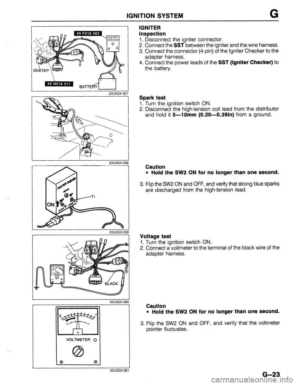
Inspection
1. Disconnect the igniter connector.
2. Connect the
SST between the igniter and the wire harness.
3. Connect the connector (4-pin) of the Igniter Checker to the
adapter harness.
4. Connect the power leads of the
SST (Igniter Checker) to
the battery.
Spark test
1. Turn the ignition switch ON.
2. Disconnect the high-tension coil lead from the distributor
and hold it
5--10mm (0.20-0.39in) from a ground.
Caution
l Hold the SW2 ON for no longer than one second.
3. Flip the SW2 ON and OFF, and verify that strong blue sparks
are discharged from the high-tension lead.
Voltage test
1. Turn the ignition switch ON.
2. Connect a voltmeter to the terminal of the black wire of the
adapter harness.
Caution
l Hold the SW2 ON for no longer than one second.
3. Flip the SW2 ON and OFF, and verify that the voltmeter
pointer fluctuates.
G-23
Page 1024 of 1164

TD TECHNICAL DATA
G. ENGINE ELECTRICAL SYSTEM
3attery Dark
current*’
Alternator 86 SOHC BP SOHC
I BP DOHC
MTX 1 ATX 1 MTX 1 ATX
Voltage V 12
Type and capacity (20-hour rate) 55D23L (60AH) 1 55D23L (60AH)
mA Max. 20.0
Type A.C
output V-A 12-65
Regulator type Transistorized (built-in IC regulator)
Regulated voltage V 14.1-14.7
Brush length Standard 21.5 (0.846)
mm (in) Minimum 8.0 (0.315)
Drive belt deflection
New 8-Q (0.31-0.35)
;riL’F,i Used Q-10 (0.35-0.39)
Coaxial
Type Direct Direct Coaxial
reduction Direct
reductior
Starter output V-kW 12-0.85 12-0.95 12-1.4 12-0.95 12-1.4
Brush length Standard 17 (0.67) 17 (0.67) 17.5 (0.69) 17 (0.67) 17.5 (0.69
mm (in) Minimum 11.5 (0.453) 11.5 (0.453) 10.0 (0.39) 11.5 (0.453) 10.0 (0.39
Distributor Electronic spark advance (photo diode)
Ignition timing BTDC
(TEN terminal of diagnosis connector grounded) 6O-8O 4O-6O 9”-11 O
Ignition coil Resistance Primary coil winding 0.81 -O.QQg
(at 20% [68OF]) Secondary coil winding lo-16 kg
SK&E-1 1 BKR5E-11
NGK
BKRGE-11 BKRGE-11
BKR7E-11
Spark plug Type
NIPPONDENSO KlGPR-Ull
K20PRUll KlGPR-Ull
K20PRUll
K22PRUll *:
. Plug gap
Firing order mm (in) 1.0-l .l (0.039-0.043)
l-3-4-2
---
’ Dark current is the constant flow of current while the ignition switch IS UFF.
(i.e engine control unit, audio, etc.) ..-
._*
T&l 0
Page 1051 of 1164

PARTS
DIFFERENTIAL ..................................... Jl-52
SHIFT MECHANISM ............................. Jl-56
TRANSAXLE ............................................ Jl-8
TRANSAXLE OIL .................................... Jl-7
MANUAL TRANSAXLE (G5M-R) .................. J2-2
DIFFERENTIAL ..................................... J2-43
SHIFT MECHANISM ............................. J2-46
TRANSAXLE.. .......................................... J2-8
TRANSAXLE OIL .................................... J2-7
MOLDING, PROTECTOR, GARNISH ...........
S-42
BELTLINE MOLDING ............................. S-48
REAR WINDOW MOLDING.. ............. S-43,44
ROOF MOLDING.. .................................. S-46
SIDE PROTECTOR ................................. S-49
UPPER WINDSHIELD MOLDING,
A-PILLAR GARNISH ............................ S-42
NEUTRAL SWITCH (MTX) . . . . . . . . . . . . . . . . . . . . . . . . . . F-l 73
0
1
\_ OIL COOLER (ENGINE). ................................ D-8
OIL PAN (ENGINE) ........................................ D-9
OIL PUMP (ENGINE) ................................... D-l 3
..................................... F-l 71
OXYGEN SENSOR
P
PARKING BRAKE ......................................... P-31
PARKING BRAKE CABLE ............................ P-32
PARKING BRAKE LEVER ............................ P-33
PARKING BRAKE SHOE ............................. P-31
PASSIVE SHOULDER BELT SYSTEM.. ..... S-103
DOOR CATCH SWITCH ....................... S-l 07
LIMIT SWITCH ...................................... S-l 07
PASSIVE SHOULDER BELT MOTOR.. S-106
SPEED SENSOR ................................... S-l 07
WARNING SWITCH .............................. S-l 07
PCV VALVE ................................................
POWER BRAKE UNIT ‘;--=I;;
..................................
POWER DOOR LOCK SYSTEM ................... S-23
DOOR LOCK CONTROL.. ...................... S-26
DOOR LOCK SWITCH.. .......................... S-26
DOOR LOCK TIMER AND RELAY.. ....... S-26
POWER STEERING.. .................................... N-23
POWER STEERING FLUID .......................... N-27
POWER STEERING OIL PUMP.. ................. N-37
POWER STEERING PRESSURE SWITCH . . F-l 73
POWER WINDOW SYSTEM.. .......................
S-27
MAIN POWER WINDOW SWITCH.. .......
S-31
POWER WINDOW MOTOR.. ..................
S-32
POWER WINDOW SUB-SWITCH ........... S-32
PRESSURE REGULATOR (FUEL). ............. F-l 29 . . . . . . . . , . . . . . , . RADIATOR CAP .............................................
E-7
RADIATOR GRILLE,
I
LOWER GRILLE MOLDING ....................... S-51 fl
RADIATOR THERMOSWITCH ...................... E-17 t
REAR AXLE ................................................. M-10
REAR BRAKE (DISC) ................................... P-23
REAR BRAKE (DRUM) ................................. P-28
REAR BUMPER ............................................ s-40
REAR COMBINATION LIGHT.. ....
REAR CROSSMEMBER ............................... R-29
REAR DOOR ................................................ S-l 5
REAR DOOR LOCK AND OPENER.. .
REAR FINISHER ........................................... s-52
REAR HATCH ............................................... s-20
REAR HATCH LOCK AND OPENER.. ......... S-22
REAR SHOCK ABSORBER AND SPRING.. R-21
REAR SIDE MARKER LIGHT ....................... T-48
REAR SIDE WINDOW REGULATOR AND . . . . . . . . .
AI .,.n
INDEX
Q
QUARTER WINDOW GLASS . . . . . . . . . . . . ..a........ S-62
R
RADIATOR . . . . . . . . . . . . . . . . . . . . . . . . . . . . . . . . . . . . . . . . . . . . . . . . . . . . . .
kiLA33 ........................................................ a-- I I
REAR SPEAKER ........................................... T-99
REAR SPOILER ............................................ s-41
REAR STABILIZER.. ..................................... R-27
REAR SUSPENSION .................................... R-20
REAR WINDOW GLASS ............................... S-63
REAR WINDOW DEFROSTER.. .................... T-74
REAR WINDOW DEFROSTER SWITCH ....... T-77
REAR WIPER AND WASHER ...................... S-74
REAR WASHER MOTOF
REAR WIPER AND WASHER SWITCH . . S-77
REAR WIPER MOTOR ............................ s-77
RELEASE BEARING (CLUTCH). . . . . . . . . . ..s..... H-17 I . . . . . . . . ...*. .*......*..
SEAT BELT.. ........................................ S-100,102
BUCKLE SWITCH.. ............................... S-l 02
SEAT ........................................................... s-110
SEPARATOR (FUEL) .................................. F-l 40
SHUTTER VALVE ACTUATOR (VICS) ........ F-l 18
SLIDING SUNROOF ..................................... S-80
MOTOR ASSEMBLY ............................... S-81
SUNROOF RELAY.. ................................ S-82
SUNROOF SWITCH.. .............................. S-82
SOLENOID VALVE
(PRESSURE REGULATOR CONTROL) .... F-135
SOLENOID VALVE (PURGE CONTROL). .. F-140
SOLENOID VALVE (VICS) .......................... F-l 18
SPARK PLUGS ............................................ G-18
-II__