engine MAZDA PROTEGE 1992 Workshop Manual
[x] Cancel search | Manufacturer: MAZDA, Model Year: 1992, Model line: PROTEGE, Model: MAZDA PROTEGE 1992Pages: 1164, PDF Size: 81.9 MB
Page 386 of 1164
F FUEL SYSTEM
FUEL SYSTEM
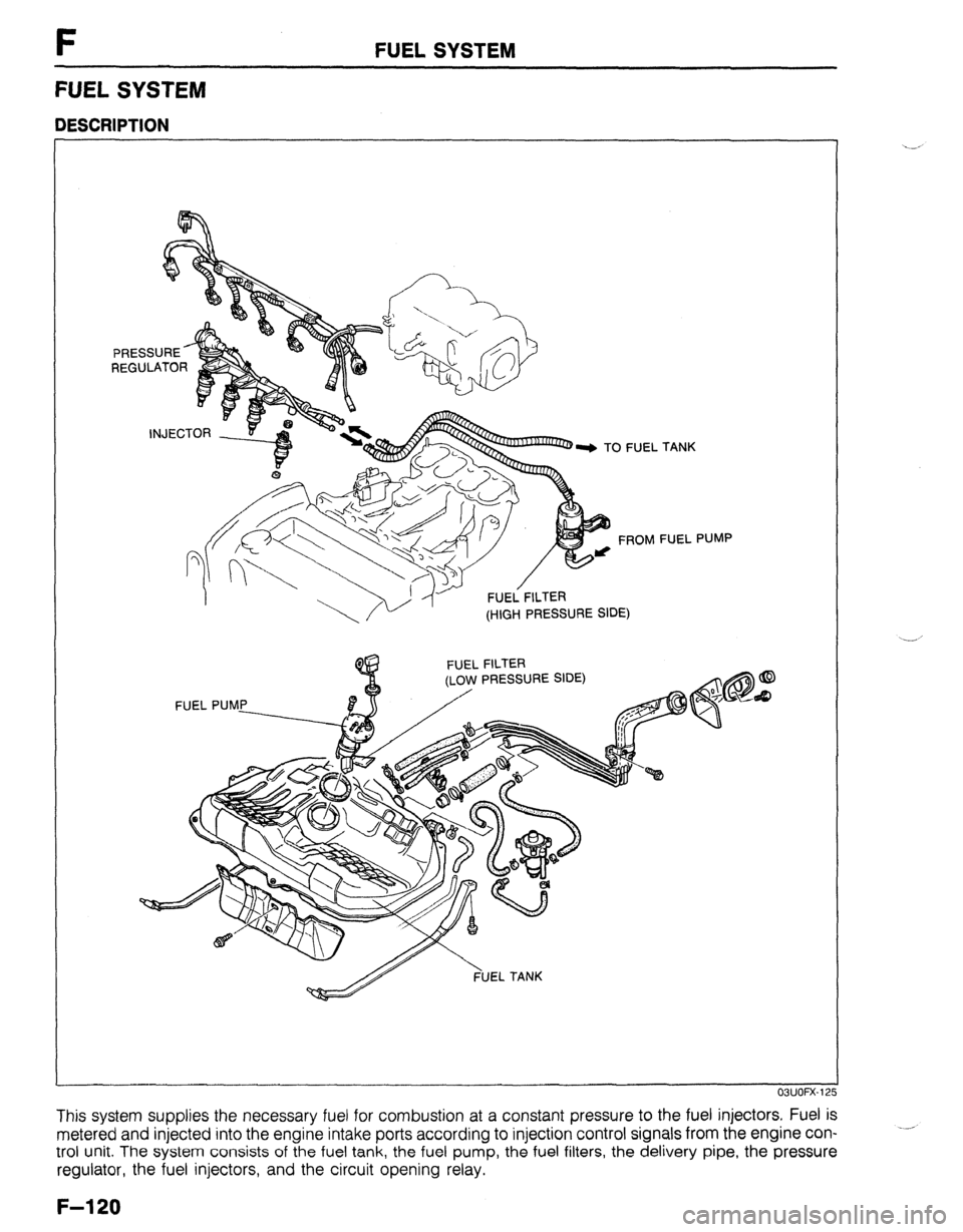
DESCRIPTION
FUEL FILTER
(HIGH PRESSURE SIDE) . TANK
FUEL PUMP
PRESSURE SIDE)
OWOFX-12
This system supplies the necessary fuel for combustion at a constant pressure to the fuel injectors. Fuel is
metered and injected into the engine intake ports according to injection control signals from the engine con-
trol unit. The system consists of the fuel tank, the fuel pump, the fuel filters, the delivery pipe, the pressure
regulator, the fuel injectors, and the circuit opening relay. ._*
F-l 20
Page 387 of 1164
FUEL PUMP CONNECTOR
/
REAR SEAT C
FUEL SYSTEM F
PRECAUTION
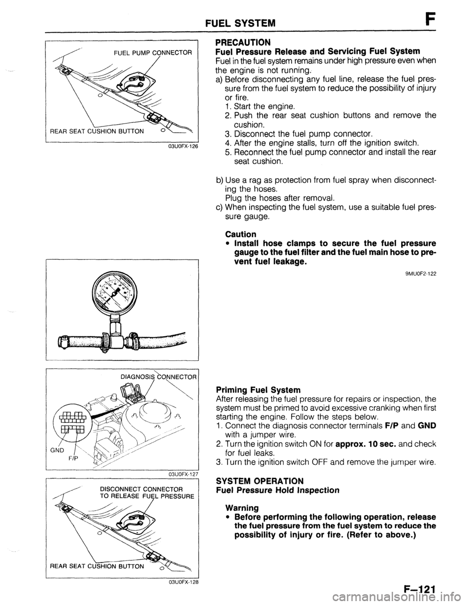
Fuel Pressure Release and Servicing Fuel System
Fuel in the fuel system remains under high pressure even when
the engine is not running.
a) Before disconnecting any fuel line, release the fuel pres-
sure from the fuel system to reduce the possibility of injury
or fire.
1. Start the engine.
2. Push the rear seat cushion buttons and remove the
cushion.
3. Disconnect the fuel pump connector.
4. After the engine stalls, turn off the ignition switch.
5. Reconnect the fuel pump connector and install the rear
seat cushion.
b) Use a rag as protection from fuel spray when disconnect-
ing the hoses.
Plug the hoses after removal.
c) When inspecting the fuel system, use a suitable fuel pres-
sure gauge.
Caution
l Install hose clamps to secure the fuel pressure
gauge to the fuel filter and the fuel main hose to pre-
vent fuel leakage.
9MUOF2-122 OBUOFX-126
DlAGNOS&O,NNECTOR
03UOFX-12.
-
DISCONNECT CONNECTOR
/ TO RELEASE FUEL PRESSURE
03UOFX-12;
Priming Fuel System
After releasing the fuel pressure for repairs or inspection, the
system must be primed to avoid excessive cranking when first
starting the engine. Follow the steps below.
1. Connect the diagnosis connector terminals
F/P and GND
with a jumper wire.
2. Turn the ignition switch
ON for approx. 10 sec. and check
for fuel leaks.
3. Turn the ignition switch OFF and remove the jumper wire.
SYSTEM OPERATION
Fuel Pressure Hold Inspection
Warning
l Before performing the following operation, release
the fuel pressure from the fuel system to reduce the
possibility of injury or fire. (Refer to above.)
F-121
Page 395 of 1164
FUEL SYSTEM F
STA
OBUOFX- 15
03UOFX-15
DISCONNECT CONNECTOR
TO RELEASE FUfL PRESSURE
REAR SEAT C
23UOFX-11
INSTALL CLAMPS
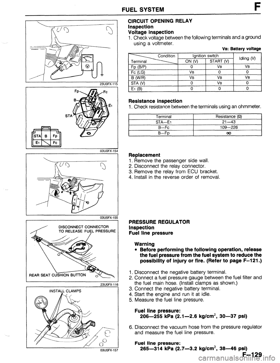
CIRCUIT OPENING RELAY
Inspection
Voltage inspection
I, Check voltage between the following terminals and a ground
using a voltmeter.
Ve: Battery voltage
Resistance inspection
1, Check resistance between the terminals using an ohmmeter.
Terminal Resistance (Q)
STA-El 21-43
B-Fc 109-226
B-Fp 00
Replacement
1, Remove the passenger side wall.
2. Disconnect the relay connector.
3. Remove the relay from ECU bracket.
4. Install in the reverse order of removal.
PRESSURE REGULATOR
Inspection
Fuel line pressure
Warning
l Before performing the following operation, release
the fuel pressure from the fuel system to reduce the
possibility of injury or fire. (Refer to page F-121.)
1, Disconnect the negative battery terminal.
2. Connect a fuel pressure gauge between the fuel filter and
the fuel main hose. (Install clamps as shown.)
3. Connect the negative battery terminal.
4. Start the engine and run it at idle.
5. Measure the fuel line pressure.
Fuel line pressure:
206-255 kPa (2.1-2.6 kg/cm2, 30-37 psi)
6. Disconnect the vacuum hose from the pressure regulator
and measure the fuel line pressure.
Fuel line pressure:
265-314 kPa (2.7-3.2 kg/cm2, 36-46 psi)
F-l 29
03UOFX-157
Page 397 of 1164
231JOFX-1
FUEL SYSTEM F
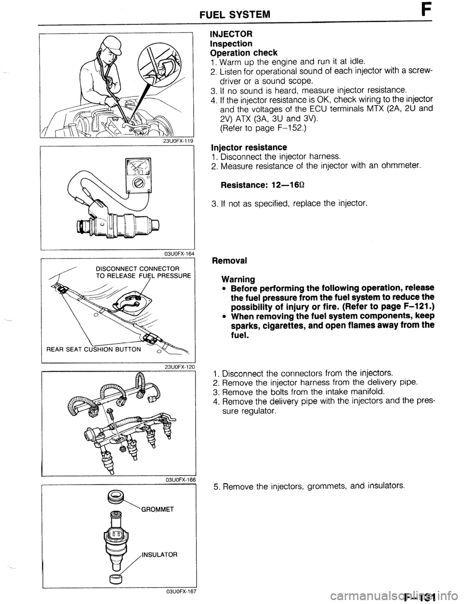
INJECTOR
Inspection
Operation check
1. Warm up the engine and run it at idle.
2. Listen for operational sound of each injector with a screw-
driver or a sound scope.
3. If no sound is heard, measure injector resistance.
4. If the injector resistance is OK, check wiring to the injector
and the voltages of the ECU terminals MTX (2A, 2U and
2V) ATX (3A, 3U and 3V).
(Refer to page F-152.)
Injector resistance
1. Disconnect the injector harness.
2. Measure resistance of the injector with an ohmmeter.
Resistance: 12-l 6Q
3. If not as specified, replace the injector.
03UOFX-1
DISCONNECT CONNECTOR
TO RELEASE FU5L PRESSUR
REAR SEAT C
23UOFX-1
OBUOFX-
GRQMMET
INSULATOR
c5
OSUOFX-
Removal
Warning
l Before performing the following operation, release
the fuel pressure from the fuel system to reduce the
possibility of injury or fire. (Refer to page F-121 .)
l When removing the fuel system components, keep
sparks, cigarettes, and open flames away from the
fuel.
1. Disconnect the connectors from the injectors.
2. Remove the injector harness from the delivery pipe.
3. Remove the bolts from the intake manifold.
4. Remove the delivery pipe with the injectors and the pres-
sure regulator.
5. Remove the injectors, grommets, and insulators.
F-131
Page 399 of 1164
FUEL SYSTEM I-
9MUOF2-17
INJEC
GRO
,:.: ‘.L.. :
,;:y :.*‘.
+:: ..y&
..: .:: ,: ,:y>
‘$pID~~ :i
..,..:,:,
,.,i. :)I,
./[::/: :
. ...:;.
/jj,.‘, ;.::,::
.’ .::: ij!/ji..
OSUOFX-17
T MANIFOLD DELIVERY’ PIPE
MUOFX-17
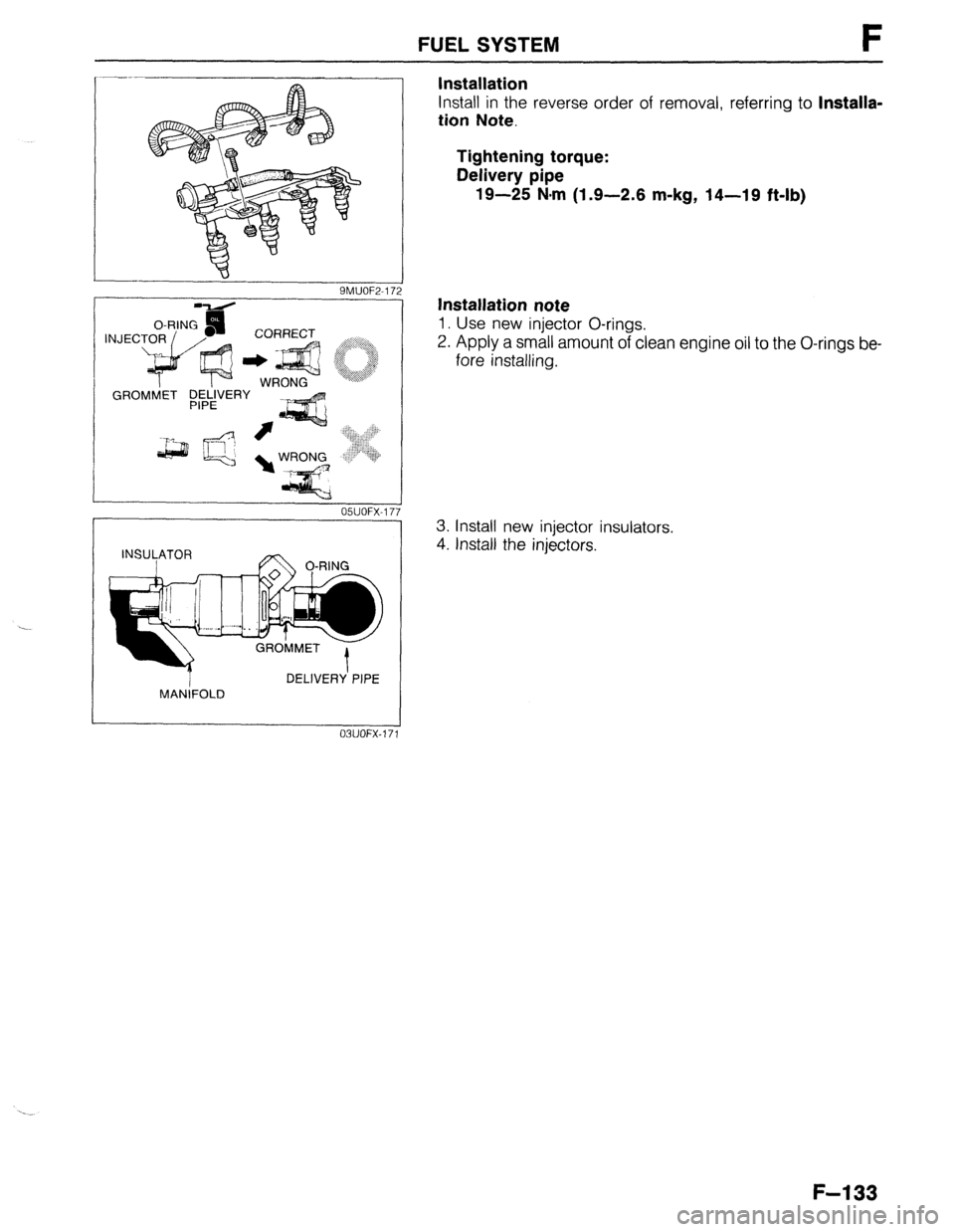
Installation
Install in the reverse order of removal, referring to Installa-
tion Note.
Tightening torque:
Delivery pipe
19-25 N.m (1.9-2.6 m-kg, 14-19 ft-lb)
Installation note
1. Use new injector O-rings.
2. Apply a small amount of clean engine oil to the O-rings be-
fore installing.
3. Install new injector insulators.
4. Install the injectors.
F-l 33
Page 400 of 1164
F PRESSURE REGULATOR CONTROL SYSTEM
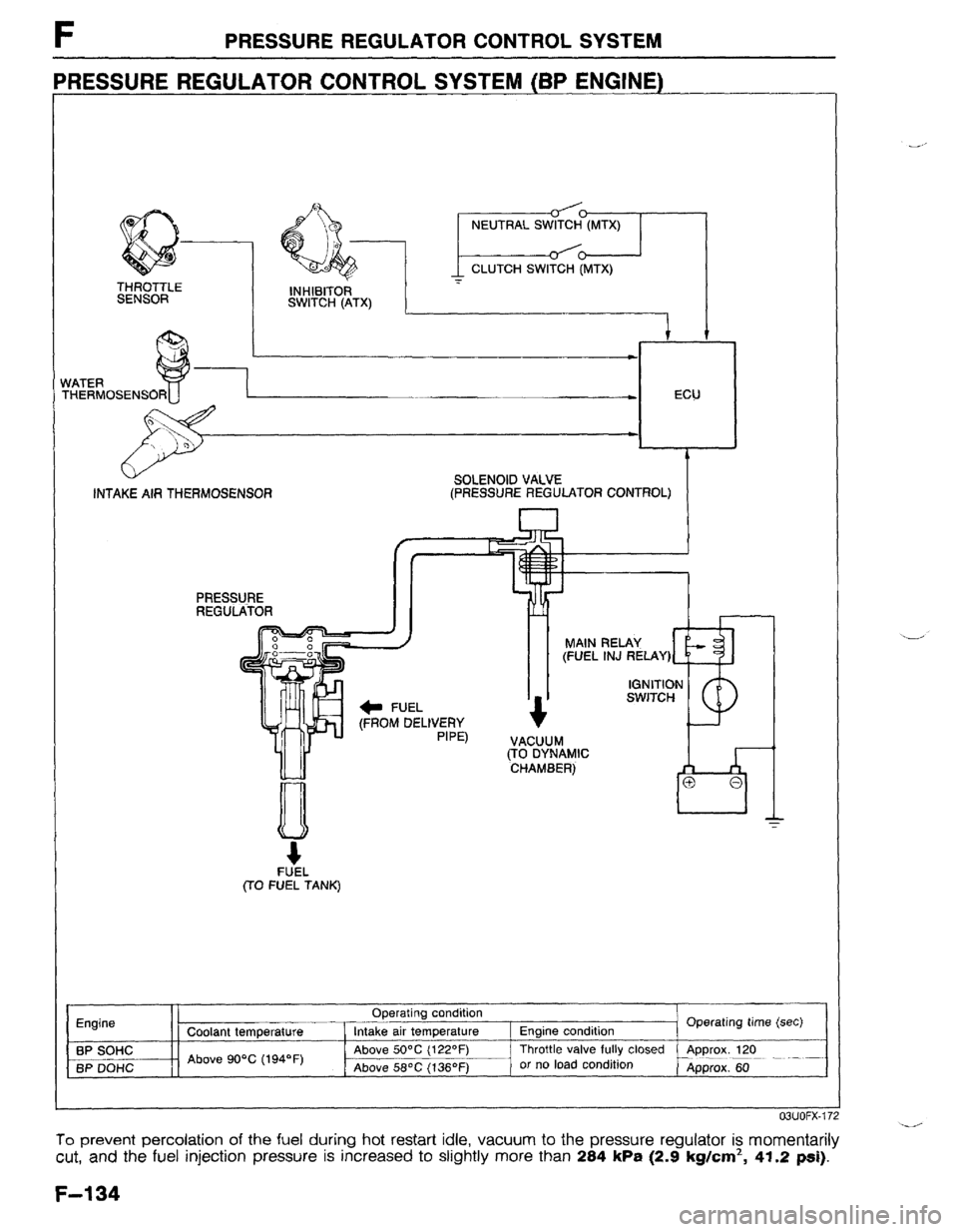
PRESSURE REGULATOR CONTROL SYSTEM (BP ENGINE)
THERMOSEN
SOLENOID VALVE
(PRESSURE REGULATOR CONTROL)
(FROM DELIVERY
FUEL
(TO FUEL TANK)
Engine
BP SOHC
BP DOHC Coolant temperature
Above 90% (194*F) Operating condition
Intake air temperature
Above 50°C (122OF)
Above 58OC (136OF) Engine condition . Operating time (set)
Throttle valve fully closed
Approx. 120
or no load condition
Approx. 60
#.nr IAt-%/ 4 7
To prevent percolation of the fuel during hot restart idle, vacuum to the pressure regulator is momentarily
cut, and the fuel injection pressure is increased to slightly more than 284 kPa (2.9 kg/cm2, 41.2 psi).
F-l 34
Page 401 of 1164
PRESSUREREGULATORCONTROLSYSTEM F
03UOFX-17
*
03UOFX-14!
OSUOFX-17
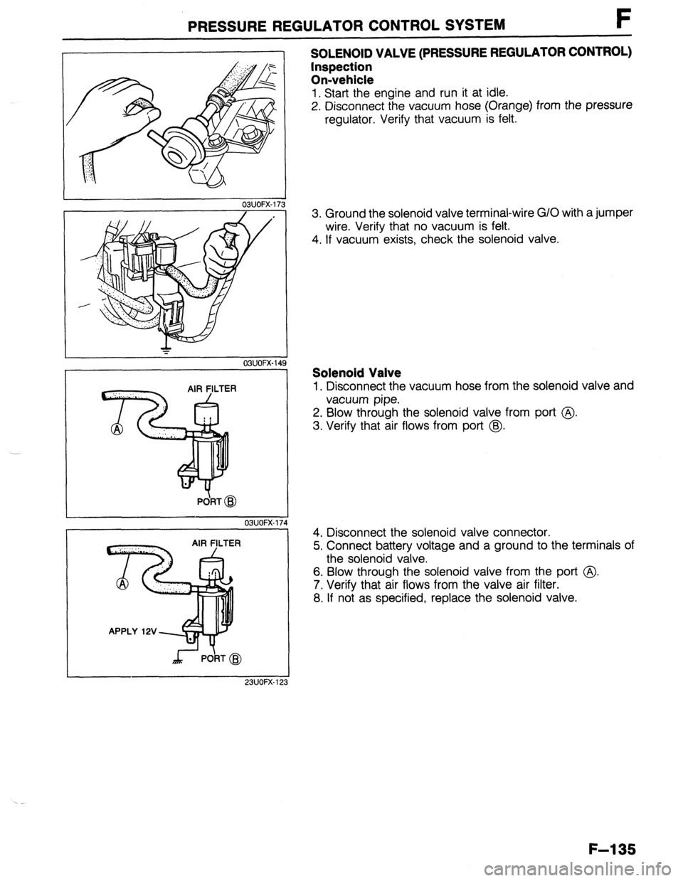
SOLENOID VALVE (PRESSURE REGULATOR CONTROL)
Inspection
On-vehicle
1. Start the engine and run it at idle.
2. Disconnect the vacuum hose (Orange) from the pressure
regulator. Verify that vacuum is felt.
3. Ground the solenoid valve terminal-wire G/O with a jumper
wire. Verify that no vacuum is felt.
4. If vacuum exists, check the solenoid valve.
Solenoid Valve
1. Disconnect the vacuum hose from the solenoid valve and
vacuum pipe.
2. Blow through the solenoid valve from port @
3. Verify that air flows from port @.
4. Disconnect the solenoid valve connector.
5. Connect battery voltage and a ground to the terminals of
the solenoid valve.
6. Blow through the solenoid valve from the port @.
7. Verify that air flows from the valve air filter.
8. If not as specified, replace the solenoid valve.
F-l 35
Page 404 of 1164
F POSITIVE CRANKCASE VENTILATION (PCV) SYSTEM
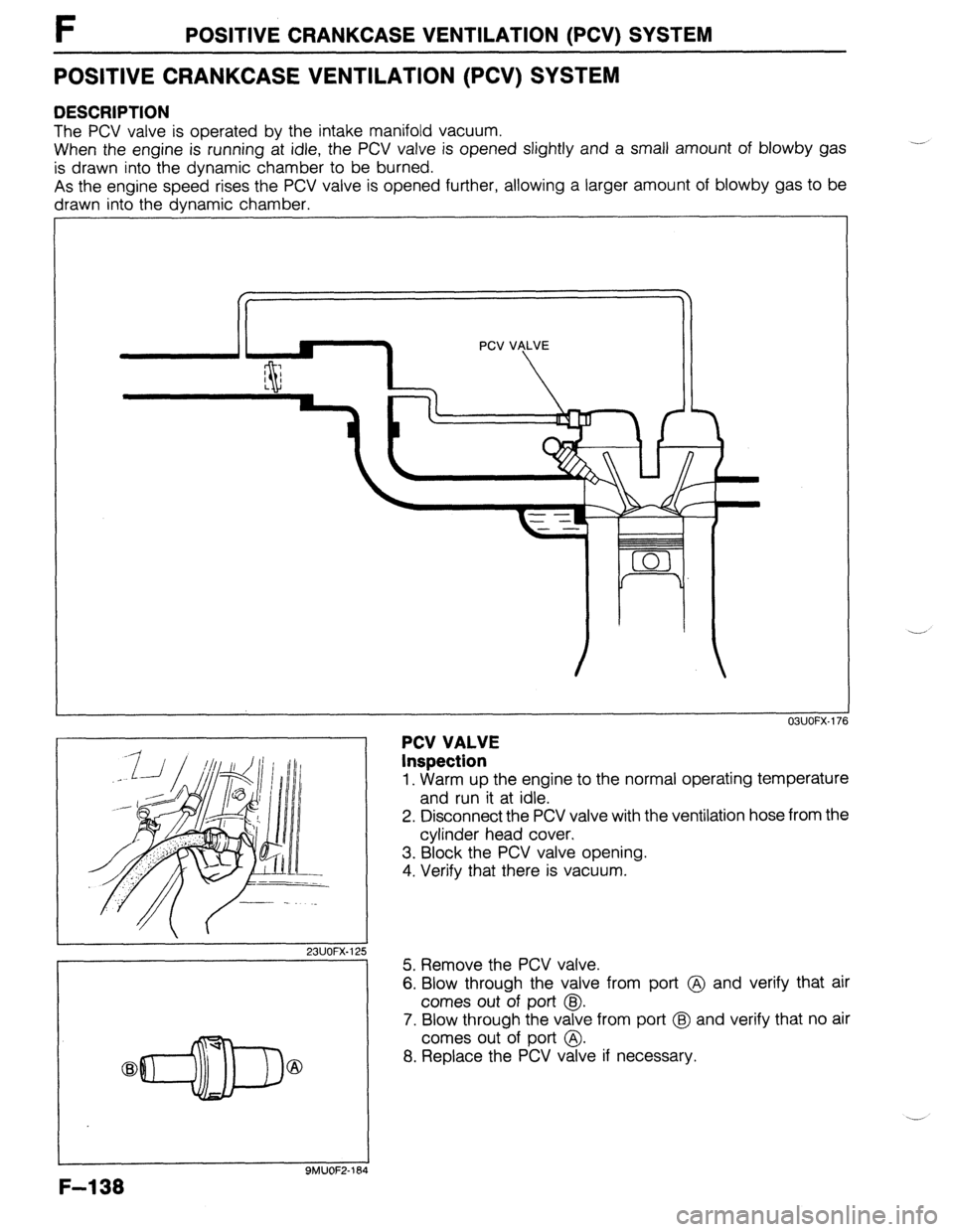
POSITIVE CRANKCASE VENTILATION (PCV) SYSTEM
DESCRIPTION
The PCV valve is operated by the intake manifold vacuum.
When the engine is running at idle, the PCV valve is opened slightly and a small amount of blowby gas
is drawn into the dynamic chamber to be burned.
As the engine speed rises the PCV valve is opened further, allowing a larger amount of blowby gas to be
drawn into the dynamic chamber.
23UOFX.1; !5
-7
F-l 38
9MUOF2-164
PCV VALVE
Inspection
OBUOFX-176
1. Warm up the engine to the normal operating temperature
and run it at idle.
2. Disconnect the PCV valve with the ventilation hose from the
cylinder head cover,
3. Block the PCV valve opening.
4. Verify that there is vacuum.
5. Remove the PCV valve.
6. Blow through the valve from port @ and verify that air
comes out of port @I.
7. Blow through the valve from port @ and verify that no air
comes out of port @.
8. Replace the PCV valve if necessary.
Page 405 of 1164

EVAPORATIVE EMISSION CONTROL SYSTEM t
EVAPORATIVE EMISSION CONTROL SYSTEM
DESCRIPTION
/ /
ENGINE ENGINE
CONTROL CONTROL - INPUT - INPUT
UNIT UNIT
- -
SOLENOID VALVE SOLENOID VALVE k k / /
CHECK VALVE CHECK VALVE
(TWO-WAY) (TWO-WAY)
CHARCOAL CHARCOAL
CANISTER CANISTER
CHECK-AND-CUTC CHECK-AND-CUTC
VALVE VALVE
SEPARATOR SEPARATOR TO ENGINE TO ENGINE SIGNALS
The evaporative emission control system consists of the separator, the check-and-cut valve, the two-way
check valve, the charcoal canister, the purge control solenoid valve, the engine control unit (ECU), and the
input devices. The amount of evaporative fumes introduced into the engine and burned is controlled by the
solenoid valve to correspond to the engine’s operating conditions. To maintain best engine performance,
the solenoid valve is controlled by the ECU.
Operation
.._ The solenoid valve (purge control) is controlled by duty signals from the ECU to perform purging of the char-
coal canister. Purging is done when these conditions are met:
(1) After warm-up
(2) Driving in gear
(3) Accelerator pedal depressed (idle switch OFF)
(4) Oxygen sensor functioning normally
F-l 39
Page 406 of 1164

F EVAPORATIVE EMISSION CONTROL SYSTEM
03UOFX-17! 3
03UOFX-180
INSTALLATION DIRECTION
F-l 40
I
23UOFX-126
03UOFX-18
OSUOFX-l&
SYSTEM OPERATION
1 Warm up the engine to normal operating temperature and
run it at idle.
2. Disconnect the vacuum hose from the solenoid valve as
shown in the figure, and verify that no vacuum is felt at the
solenoid valve. -.
3. If not as specified, check the solenoid valve.
SOLENOID VALVE (PURGE CONTROL)
Inspection
1. Disconnect the vacuum hoses from the solenoid valve.
2. Verify that no air flows through the valve.
3. Disconnect the solenoid valve connector and supply bat-
tery voltage as shown in the figure.
4. Verify that air flows through the valve.
5. If not as specified, replace the solenoid valve.
SEPARATOR
Inspection
1. Remove the left side trim.
2. Remove the separator.
3. Visually check the separator for damage. Replace it if
necessary.
CHECK VALVE (TWO-WAY)
Inspection
1. Remove the valve.
2. Check the operation of the valve with a vacuum pump.
Apply approx. 37 mmHg (1.46 inHg)
vacuum at port A Airflow
Apply approx. 44 mmHg (1.73 inHg)
vacuum at port B Airflow