engine MAZDA PROTEGE 1992 Workshop Manual
[x] Cancel search | Manufacturer: MAZDA, Model Year: 1992, Model line: PROTEGE, Model: MAZDA PROTEGE 1992Pages: 1164, PDF Size: 81.9 MB
Page 447 of 1164

CHARGING SYSTEM G
TROUBLESHOOTING
INSPlhdN
ACTION
1
Check battery voltage Yes Go to next step Specification: Above 12.4V
No
Check battery ri-page G-8
2 Start engine and check if alternator warning
Yes Go to Step 4
lamp goes out
No Go to next step
3 Check if voltages at alternator terminals are Yes Check wire harness between battery and terminal B
3. Turn all electrical loads ON and depress
2,500-3,000 rpm
l Do not ground terminal B
G-7
Page 449 of 1164

CHARGING SYSTEM G
RUB
PRO
03UOGX-01
Terminal and cable
1. Check the tightness of the terminals to ensure good electri-
cal connections.
2. Check for corroded or frayed battery cables.
3. Check the rubber protector on the positive terminal for prop-
er coverage.
4. Clean the terminals if necessary, and coat them with grease.
Recharging
Battery
55D23L Slow charge Quick charge
(A) (4
Under 6 Max. 20
Slow charging
It is not necessary to remove the vent caps to perform a slow
charge.
Quick charging
Remove the battery from the vehicle and remove the vent caps
to perform a quick charge.
Warning
l Before performing maintenance or recharging the
battery, turn off all accessories and stop the engine.
l The negative cable must be removed first and in-
stalled last.
l Set the battery in water when quick charging to pre-
vent overheating the battery.
G-9
Page 450 of 1164

G
ALTERNATOR
Removal / Installation
CHARGING SYSTEM
Caution
l Be sure the battery connections are not reversed, because this will damage the rectifier.
l Do not use high-voltage testers such as a megger, because they will damage the rectifier.
l Remember that battery voltage is always applied to the alternator B terminal.
l Do not ground the L terminal while the engine is running.
l Do not start the engine while the connector is disconnected from the L and S terminals.
1. Remove in the order shown in the figure.
2. Inspect all parts and repair or replace as necessary
3. Install in the reverse order of removal.
N.m (m-kg, R-lb)
OSlJOGX b20
1. Negative battery cable
2. Vacuum hose
3. Solenoid bracket (If equipped)
4. Connector
5. B terminal wire
Inspect for damage and corroston 6. Drive belt
Inspection. . . . ., ~.. ,. ,.... . , page G-l 4
Adjustment ,~, ,.,., ,. ,. ,, ,.. page G-l 4
Replacement . . . . . . . . page
G-l 4
7. Alternator
Disassembly / Assembly ,........,... page G-l 1
Inspection... ,, . . . . . . . . . . . . . . . . . . . . . . . . . . . page G-l 2
G-10
Page 456 of 1164

G IGNITION SYSTEM
TROUBLESHOOTING
iTEP
INSPECTION
ACTION
1
Check if MIL illuminates when engine is running Yes Check for malfunction code number
and perform troubleshooting (TEN ter-
minal grounded) c7 Section F
No Go to next step
2 Drsconnect high-tension lead from distributor and
Yes
check for strong blue spark while cranking en-
l Check distributor cap and rotor v page G-22
gine * Check high-tension lead
KP page G-19 c7 page G-17
+ Ignition system normal
No
Go to next step
3 Check if resistance of ignition coil is OK
Yes
Go to next step ~7
page G-19
Specification (at 20°C [66”9):
Primary coil winding: 0.81-0.99Q No
Replace ignition coil
Secondary coil winding: IO-16 kQ
-i
Check if resistance of high-tension leads is OK Yes Go to next step
D= page G-17
Specification: 16 kQ per 1 m (3.28 ft)
No Replace high-tension lead
5 Check if igniter is OK
m- page G-23 Yes
Replace ECU
No
Replace igniter
03UOGX-03
G-16
Page 457 of 1164

IGNITION SYSTEM G
r
03UOGX-03
SOHC
LOCK BOLTS
DOHC
A LOCK BOLTS I 03UOGX-0’
03UOGX-C
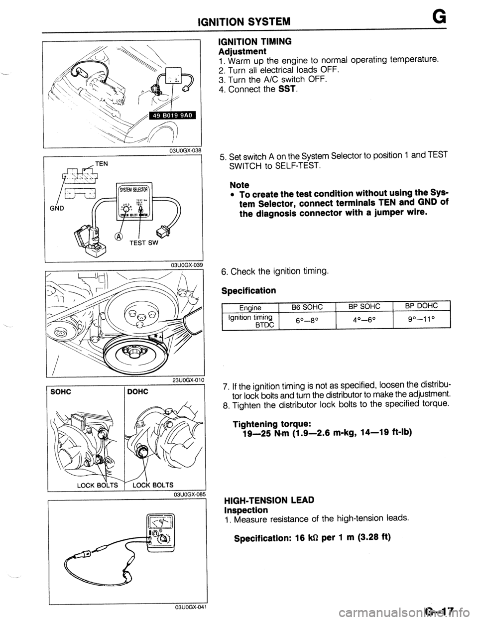
IGNITION TIMING
Adjustment
1. Warm UD the enaine to normal operating temperature.
2. Turn all ‘electricarloads OFF.
3. Turn the A/C switch OFF.
4. Connect the
SST.
5. Set switch A on the System Selector to position
SWITCH to SELF-TEST. 1 and TEST
Note
l To create the test condition without using the Sys-
tem Selector, connect terminals TEN and GND of
the diagnosis connector with a jumper wlre.
6. Check the ignition timing.
Specification
Engine
Ignition timing
BTDC B6 SOHC BP SOHC
60-8O 4O-6O
BP DOHC
9°-110
7. If the ignition timing is not as specified, loosen the distribu-
tor lock bolts and turn the distributor to make the adjustment.
8. Tighten the distributor lock bolts to the specified torque.
Tightening torque:
19-25 N-m (1.9-2.6 m-kg, 14-19 ft-lb)
HIGH-TENSION LEAD
Inspection
1. Measure resistance of the high-tension leads.
Specification: 16 kg per 1 m (3.26 ft)
G-l 7
Page 458 of 1164

G IGNITION SYSTEM
-.-.. .----___ 03UOGX-042
03UOGX-04
--.---- J
03UOGX-044
WEAR AND CARBON
/
c- -BURNT
PLUG GAP
L--
c
DAMAGE AND
,llllll....*llll,lllf DETERIORATIOF
; -,DAMAGE
03UOGX.04
G-18
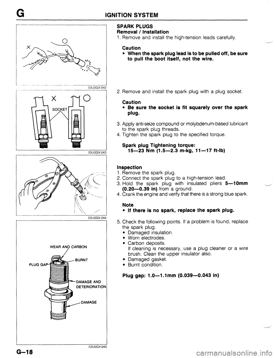
SPARKPLUGS
Removal / Installation
1. Remove and install the high-tension leads carefully.
Caution
l When the spark plug lead is to be pulled off, be sure
to pull the boot itself, not the wire.
Y’
2. Remove and install the spark plug with a plug socket.
Caution
l Be sure the socket is fit squarely over the spark
plug.
3. Apply anti-seize compound or molybdenum-based lubricant
to the spark plug threads.
4. Tighten the spark plug to the specified torque.
Spark plug Tightening torque:
15-23 N.m (1 S-2.3 m-kg, 11-17 f&lb)
Inspection
1. Remove the spark plug.
2. Connect the spark plug to a high-tension lead.
3. Hold the spark plug with insulated pliers
5-10mm
(0.20-0.39 in) from a ground.
4. Crank the engine and verify that there is a strong blue spark.
4
Note
l If there Is no spark, replace the spark plug.
5. Check the following points. If a problem is found, replace
the spark plug.
l Damaged insulation.
l Worn electrodes.
l Carbon deposits.
If cleaning is necessary, use a plug cleaner or a wire
brush. Clean the upper insulator also.
l Damaged gasket.
l Burnt condition.
Plug gap: 1.0-l .l mm (0.039-0.043 in)
Page 459 of 1164

IGNITION SYSTEM . . . ._,
03UOGX-04
Lszl /
P
0 V
- 23UOGX-OC
03UOGX-048
03UOGX-04
03UOGX-0%
IGNITION COIL
Inspection
Spark test
1. Disconnect the high-tension lead from the distributor.
2. Hold it with insulated pliers 5-l
Omm (0.20-0.39 in) from
a ground.
3. Crank the engine and verify that a strong blue spark is
visible.
4. If there is no spark, disconnect the connector from the igni-
tion coil and check for voltage at the positive (+) terminal
of the connector with the ignition switch in the ON position.
Specification: Battery voltage
5. If there is no voltage, check the main fuse, ignition switch,
and wire harness.
Primary coil winding
1. Use an ohmmeter and measure resistance of the primary
coil winding. If not within specification, replace the coil.
Prlmary coil resistance: 0.81-0.99112 (at 2O*C [88*F])
Secondary coil winding
1. Use an ohmmeter and measure resistance of the secon-
dary coil winding. If not within specification replace the coil.
Secondary coil resistance: lo-18 kQ (at 20°C [68*F])
Insulation of case
1. Use a 500V megger tester to measure the insulation resis-
tance between each terminal and the case.
Speclficatlon: 10 MS1 min.
G-19
Page 460 of 1164

G IGNITION SYSTEM
I
03UOGX~051
03UOGX-052
DISTRIBUTOR
Spark Test
1. Disconnect the high-tension lead from each spark plug.
2. Hold each insulator with pliers
5-10mm (0.20-0.39 in)
from a ground.
3. Crank the engine and verify that a strong blue spark is
visible.
Electronic Advance Inspection
1. Verify that the ignition timing advances with engine ac-
celeration.
G-20 ._... -~
._ _
Page 470 of 1164

G STARTING SYSTEM
1 03lJOGX.079
23LJOGX-011
I I OBUOGX-081
3. Place the armature on V-blocks, and measure the runout
with a dial indicator.
If the runout is not within specification, repair it with a lathe
or replace the armature.
Runout: 0.05mm (0.002 in)
Maximum: O.lmm (0.004 in)
4. Replace the armature if the outer diameter of the commu-
tator is almost at or less than the grind limit.
5. If the commutator surface is dirty, wipe it with a cloth; if it
is rough, repair it with a lathe or fine sandpaper.
Engine
Grind limit mm (in) 1 B6 1 BP (MTX) 1 BP (ATX)
31.4 (1.24) 1 28.8 (1.13)
6. Segment groove depth
If the depth of the mold between segments is almost at or
less than the minimum, undercut the grooves to the stan-
dard depth.
Depth: OS-0.8mm (0.02-0.03 in)
Minimum: 0.2mm (0.008 in)
Bearing (if equipped)
1. Check for abnormal noise, looseness, or sticking.
2. Replace the bearing(s) if necessary.
I
03UOGX-082
G-30
Page 471 of 1164

STARTING SYSTEM G
STARTER INTERLOCK SWITCH (MTX)
CONTACT
IGNITION SWITCH
IG2 ROD
p IG1 ‘NTERlfM$TCH
i BATTERY
I
STARTER
For operator safety, if the clutch pedal is not depressed during starting, battery power will not be supplied
to the starter and the engine will not crank.
Interlock Switch
Inspection
1. Disconnect the interlock switch connector.
2. Connect an ohmmeter to the switch.
3. Check the continuity.
Clutch pedal
----- I_
Depressed
Released 4.
Replace the switch if necessary.
Continuity
--
Yes
No
G-31